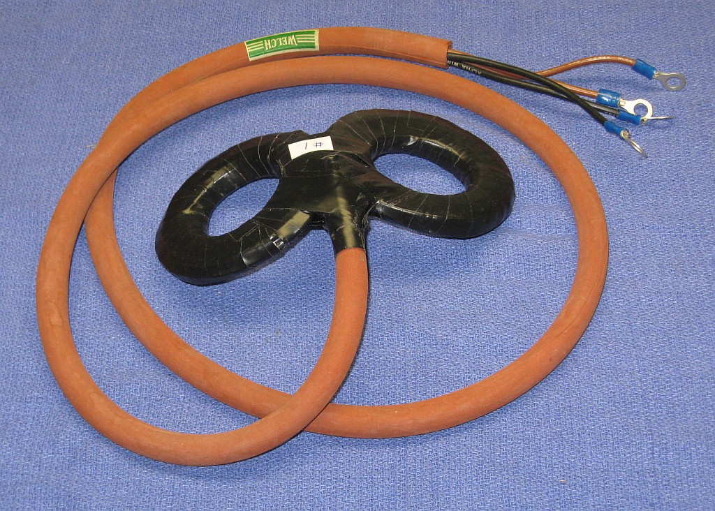
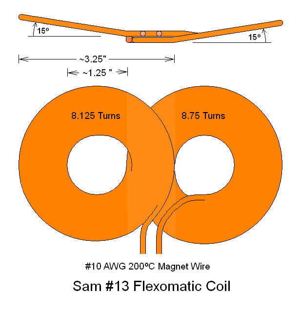
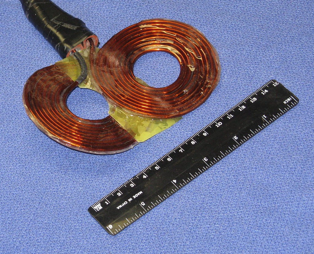
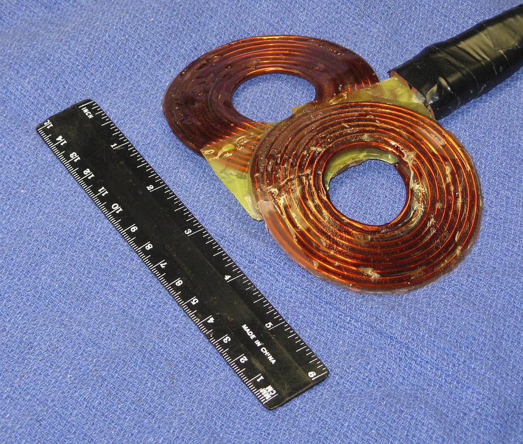
Note: For the captions, "Toroid" is a bundle of wire wound with a roughly circular cross section, "Pancake" is a single layer of wire wound in a tight spiral, "Stacked" refers to multiple pancakes on top of one-another, "15T" denotes 15 turns, "2x5T" denotes 10 turns total in 2 pancakes of 5 turns each stacked, "D" is mean diameter.
Unless otherwise noted, the following air-core coils ran without problems, meaning that the pulser did not self destruct, at least during brief testing. :) However, only Sam #13 (the last one constructed to date) produces any cerebral response, and only with a minimum of 70 or 80 Joules of stored energy. Some or all of the other air-core coils may also work at a higher energy level but have not been tested with more than around the 26 J of the Ver. 1 pulser. However, at this energy, most of the air-core coils were truly excellent for peripheral nerve stimulation, and could launch aluminum rings across the room. ;-) The two iron-core coils were, to put it mildly, total duds in every respect, except perhaps for use as ugly paperweights. ;( :)
Sam #1 was the initial test coil. Its design was based on the desire to have an inductance that would result in a biphasic period of 200 to 300 µs with the 25.6 µF energy storage capacitors of the Ver. 1 pulser, and have the physical appearance of a figure-8 TMS coil. ;-) The windings used #14 AWG stranded wire with PVC and outer plastic insulation. Its inductance was around 67 µH. Sam #1 functioned perfectly with a biphasic period of around 261 µs. It just proved useless for TMS, at least at the energy of the Ver. 1 pulser. However, Sam #1 did provide a truly fabulous neck massage and abdominal workout via peripheral nerve stimulation at 10 pps. ;-) Of all the coils constructed to date, it was probably the best in this regard.
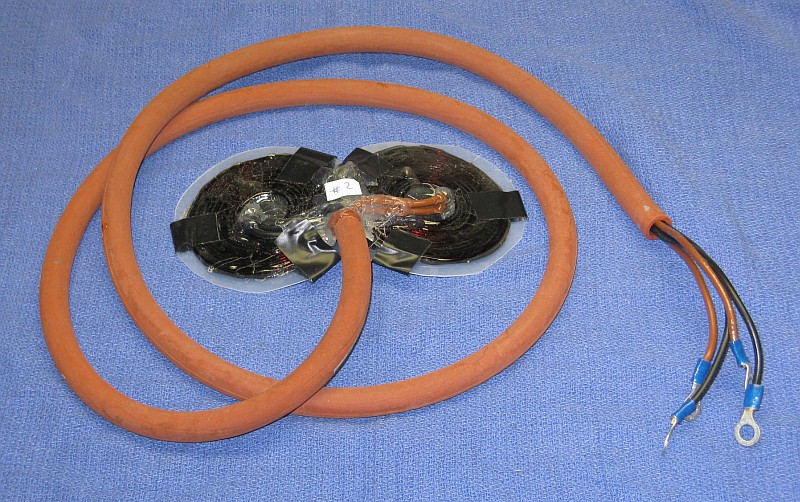
Sam #2 was also a twin coil design but the individual coils were pancakes instead of toroids. It was wound with #14 magnet wire laminated between plastic sheets. The twin pancake coils were side-by-side. Its inductance was around 34 µH, about half of that of Sam #1 so the biphasic period was around 164 µs. It was used to record the waveforms for the biphasic, polyphasic, and monophasic pulse types thus confirming the validity of the electronic design. This was done using a sense coil and integrator resulting in the scope photos in the pulser document.
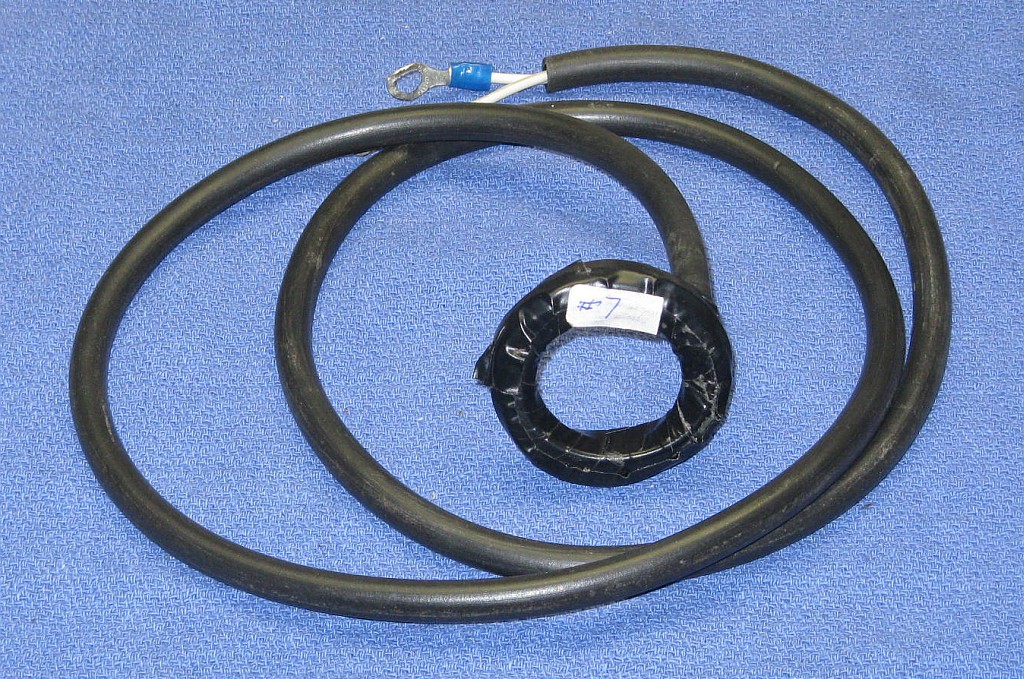
These were very simple single-loop coils. Sam #4 had the lowest inductance of any that had been built - around 3 µH resulting in a biphasic period of only 65 µs. Based on calculations, its peak dB/dt would be similar to that of Sam #13. The others were around 10 µH. All were wound with #14 AWG stranded insulated wire as above.
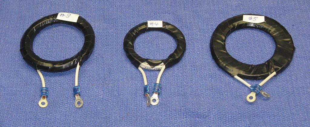

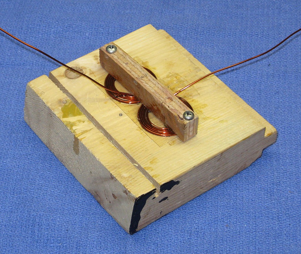

Calculations for Sam #10 predict that it should actually have the highest dB/dt of all the coils shown here. It is of similar construction with an average pancake diameter of only 3 cm, 6 turns per pancake, and a total inductance of around only 3.8 µH, the peak dB/dt should be almost 16 kT/s at 2 cm, and over 65 kT/s on its surface.
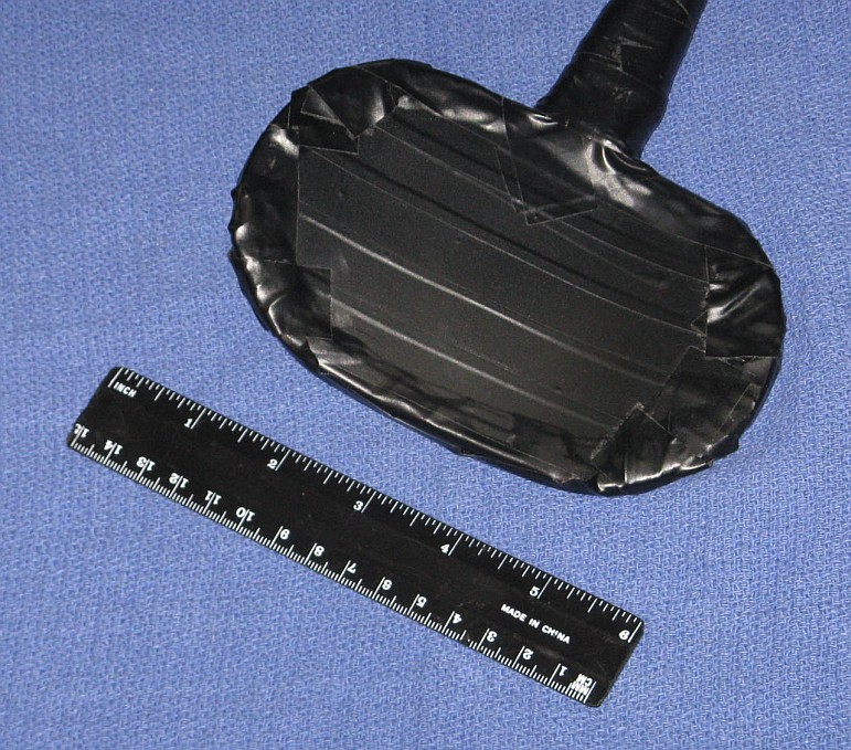
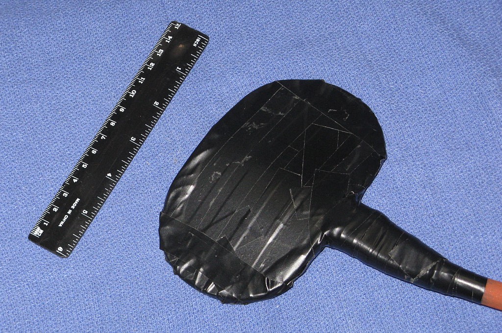
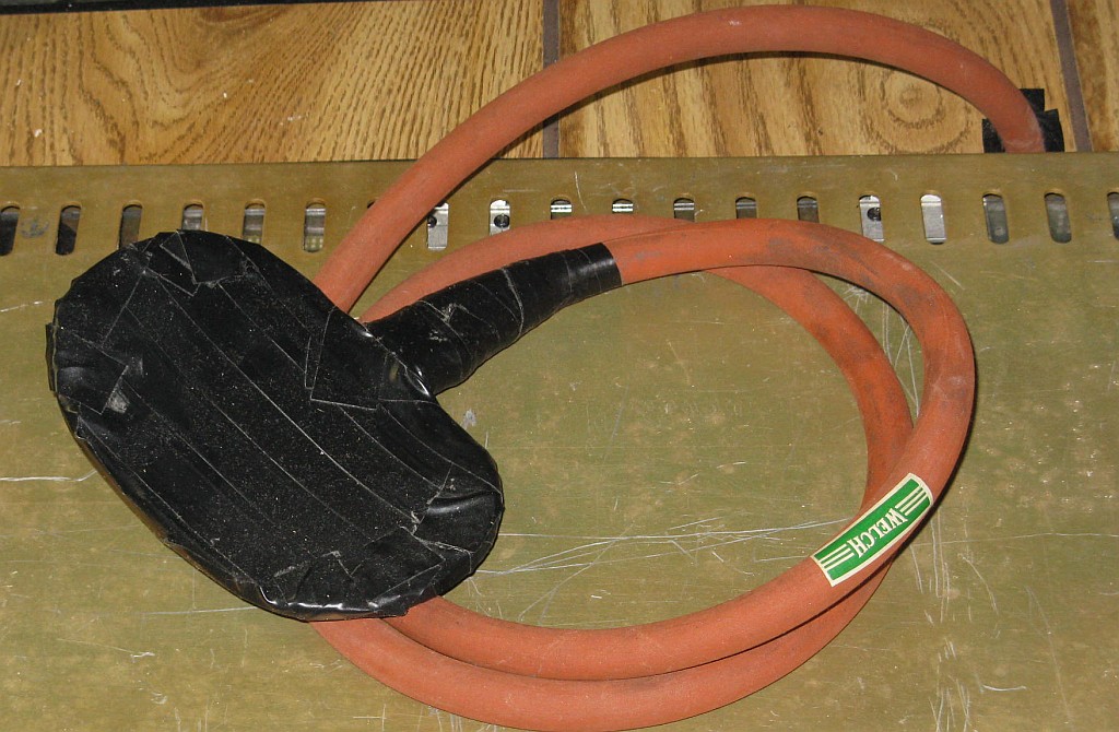
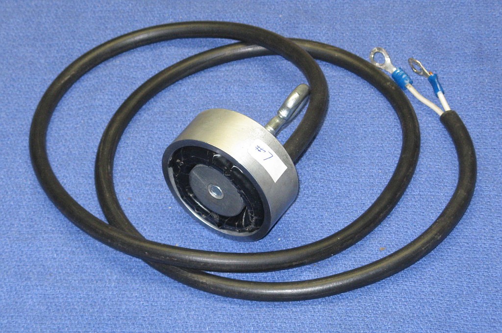
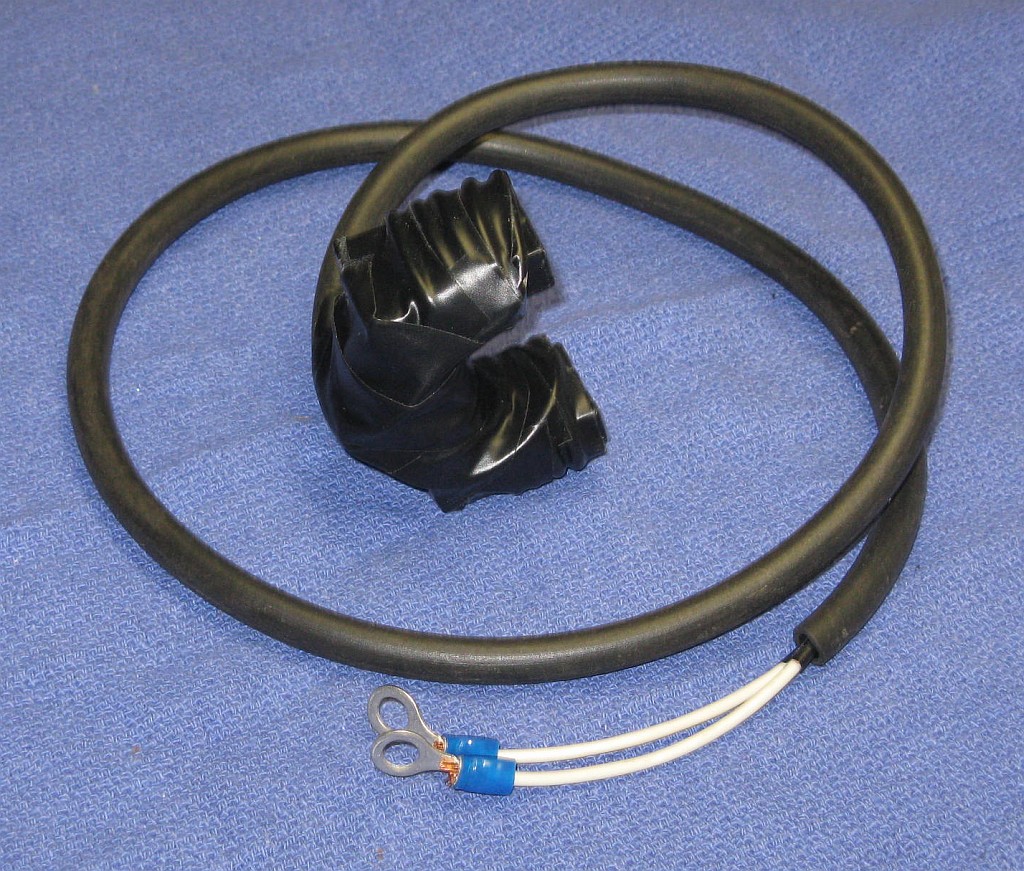
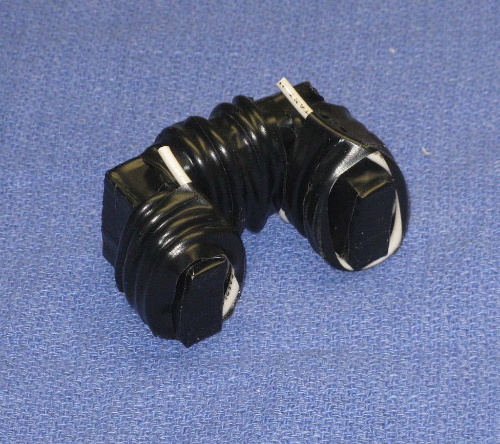
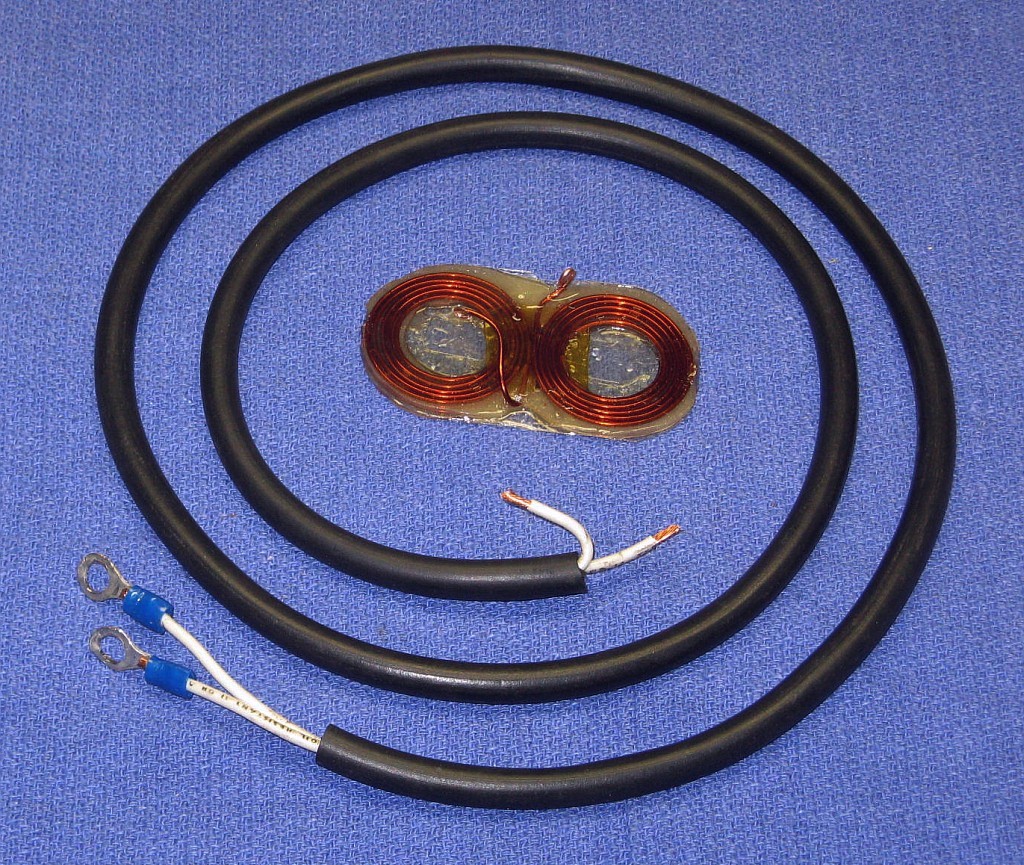
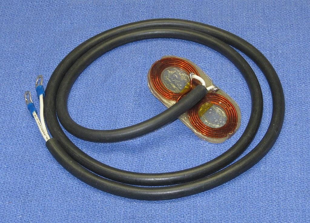
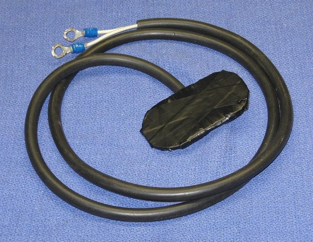
As with the ones above, a jig is used to fix the coils during initial construction and gluing. The coils are insulated where they overlap by a piece of 0.02" Fiberglas-Epoxy PCB unplated material. After forming the wings, they were coated first in Epoxy and then RTV Silicone (Loctite 37467 Black RTV 598) with a pair of 0.02" Fiberglas-Epoxy PCB unplated sheets providing the primary high voltage insulation front and rear. Edges have Epoxy, RTV, two layers of 0.001" Kapton/Polyamide tape. Then the entire structure was covered in at least one layer of vinyl electrical tape. The cable is 3 #14 AWG flexible insulated wires for each direction inside a rubber hose for additional insulation. The equivalent wire is between AWG #10 and 9. The resistance is approximately 0.01 ohms for the coil and 0.008 ohms for the cable.
Testing with a Gauss probe at low current results in slightly more than 1 G/A at 2 cm (~0.8") from the coil surface near the center ("sweet spot").
Sam #13 is the only coil so far to have evoked a consistent cerebral neural response but this is most likely due to the fact that it is also the only one to have been used with the Ver 2. pulser and its higher energy of up to more than 175 J. All the others were only used at a maximum energy of around 27 J. Some some of those would probably have some effect, though Sam #13 is believed to be the best.
-- end V1.10 --