For contact info, please see the Sci.Electronics.Repair FAQ Email Links Page.
Copyright ©; 1994-2021
Reproduction of this document in whole or in part is permitted if both of the
following conditions are satisfied:
1.This notice is included in its entirety at the beginning.
We will not be responsible for personal injury resulting from attempting
these repairs nor damage to the equipment that may result from lack of
soldering experience or inadequate desoldering or soldering equipment.
Also, some LXI TVs may actually be of RCA/GE manufacture: LXI is sold by
Sears. If the model number starts with 274.something it is an RCA CTC176/7
or 187 chassis. (pwhite4@aol.com (PWhite4).)
Sometimes, similar symptoms are the result of bad solder connections elsewhere
on these chassis. Check around the pins of large components like power
transistors, power resistors, transformers, etc. However, since problems with
the tuner soldering are so common, this is usually the place to start.
Note that many other RCA chassis as well as other manufacturer's TVs are also
susceptible to similar symptoms with similar causes.
Some of the common symptoms include:
The articles in this document have been compiled over the last few
months from postings on the USENET newsgroup sci.electronics.repair.
Contributions are welcome to increase the coverage of this set of notes
as well as those for the very similar set of problems and solutions for
late model Sony TVs: "Sony TV Tuner and IF Solder Connection Problems".
(Symptoms are very similar and repair requires removing and resoldering
connections inside the tuner and IF boxes. Unfortunately, at least on
some models, removing these modules is a real treat!)
Proper attributions will be made for all providers of solutions. I apologize
if I have incorrectly referenced you or left your name off. I will be happy
to make any necessary corrections in the next revision. Please email me
with any additional sections. I would very much like to improve the details
of the repair procedure if possible.
Corrections and additions to any specific symptom or solution are also
welcome.
I have no connection with Thomson Electronics or any other manufacturer
of consumer electronics. These articles have been included unedited except
for some spelling, grammar, and format cleanup.
The CTC195/197/203 series with the onboard tuner has a batch of other
problems, not the same type of failures that the CTC177 line was
notorious. Most of which are addressed with service bulletins given the
units serial number. However they are suffering from a conductive glue
syndrome the Thomson engineers are still in denial about. It seems the
glue they are using to attach the surface mount components is
sometimes becoming conductive from the manufacturing process and will
cause all kinds of really odd intermittent problems, most of which cannot
be fixed unless you get lucky enough to see it several times while
working on the set. Specifically c17503 and c17504 inside the tuner, and
some down by the microcontroller are the most common culprits.
The latest Thomson sets we have been seeing have a stand up tuner that
runs off the I2C bus, but those are failing at an alarming rate. Seems
they are using the same I2C prescaler IC by Philips that Zenith and Sony
are using and also having high failure problems. If you generate too
much static by sneezing near the cable line you can blow one of these
ICs. For a cheap TV set if you can live with the poor focus, contrast,
and poor convergence on most of the Thomson sets, they are comparable
with everything else that is selling that cheaply.
"This picture is short vertical about 1/2 inch at top and two inches at
the bottom. Anyone seen this problem on this chassis. Is it possibly
related to all the bad solder joints in the tuner area?"
"I have an RCA TV with the following symptoms:
"My parents' RCA TV has lost some volume, and is now barely audible
when on full volume. The controls are all electronic and on screen. Is
this a known problem with RCAs, and could there perhaps be a pot I
could adjust inside to 'boost' the volume?"
"I have a GE 31" (about 3 years old) where the picture moves down the
tube, like a DC offset is present. The top of the picture is down
about 1/3 from the top of the screen and the bottom of the picture
compresses. Occasionally, the picture turns to snow. If I turn off
the power and back on, it temporarily cures the problem. Could these
symptoms also be caused by poor tuner connections?"
"I have the SAME TV, and mine is about 1/5 off. Some channels also have
lots of Snow etc."
"I tried using a VCR as a tuner & running the signal in through the RCA
plugs in the back. Same difference. I still experience the same problems.
Does this rule out the turner?"
"I am having the following problem with the TV:
"My RCA XL-100 TV has begun to develop a life of its own -- it intermittently
goes crazy."
"My two and a half year old GE 25" set started having troubles with the
picture shrinking from top to bottom, losing signal strength (snow) and
now shifting of the picture off the bottom of the screen. This would
occur usually right after turning it on, and sometimes could be cured by
turning off the set and turning it back on again. Lately it has been
getting worse so I took it in for repair. Lo and behold, there were
several GE and RCA sets there that had similar complaints. All ended up
needing an "S-kit" from GE, an item apparently supplied to the repair
center for free from GE. I needed a crystal as well. This sounds like
some kind of widespread problem that maybe should be looked at as if it
is an unwritten warranty? Anyone care to comment?"
"I have a 27" GE Model 27GT610. About a year ago a problem started to
develop. It would take turning it on 2-3 times before the picture came
up. Initially all I would get was a black screen and static on the
speakers as if it wasn't on a broadcast channel. Over the last year it
has progressed to taking me 20-30 minutes to get the picture to come on.
I suspect it might be a corroding startup relay but am unsure. Does
anyone have a part# and component# that could point me in the right
direction? Any other suggestions would also be appreciated. Thanks, btw
I already have the FAQ.
"I have a 2 year old RCA XL100 television. It has worked just fine up
until the last 2 or 3 weeks. I now have severe problems with it and am
hoping that someone who reads this posting will recognize the symptoms
and help steer me in the right direction to fix the damned thing! I know
of another person who had the exact same model and 2 years after he
bought it, it started acting up in the same way, so I assume this is a
well documented problem that I'm seeing...
When the set is turned on, the "reception" on some cable channels is
terrible, but others are fine. Turning off and on again fixes those
channels, but within a few seconds, the reception goes bad again. There
is a time display function and a mute function on the TV. When I press a
button, the channel displays in the upper right corner. Likewise in the
lower left corner with mute. When the TV is misbehaving, these words
"walk" down on the set. The MUTE word goes so far that it's unreadable
since only the tops of the letters show. Turning off and then back on
temporarily solves the problem. Whenever this phenomenon occurs, the top
of the picture gets "squashed" down and a black band appears at the top
of the screen. When I look at CNN, the sportsticker at the bottom is
almost unreadable and it appears that the lower part of the picture is
forced into the non-viewable area of the screen. If I struggle through
these problems for an hour or so, then everything is almost back to
normal, but the problems do appear intermittently. When I switch over to
the VCR tuner, my reception problems are solved, but I still get the
screen "walking" behavior, so it looks to be more that the tuner chip
(unless that also controls these extra functions). Does anybody know
about this problem??? Is it just a bad chip or component that I can
replace? What should I do about it? (I'm a EE and am quite capable of
fixing simple soldering problems and such myself). Before I take it to a
repair shop or buy a new one, I'd like to see if I can fix this one...
in a word... HELP!"
"I have an RCA FMR70ER TV that only works when the room temperature is warm.
If the temperature is cool the TV will never turn on .
"The problem tends to show up after the TV has been on for a few minutes.
The picture will appear to have signal problems (i.e. a snowy picture), and
then the top line of the picture will begin to dip down, until it is
approximately 25% of the way down the tube. There is just black above it.
When its really bad, the picture will be just snow, the top will drop down
almost half, and there will be a very bright band at the bottom of the
screen. Now, one way to remedy this problem is to shut the TV off, and
then back on again. Sometimes this will 'reboot' the TV and the picture is
fine. Sometimes it doesn't work.
The problem is beginning to become more persistent and annoying!"
"I have a General Electric 21" (or 23"...can't remember) colour remote
control television. It's about two and a half years old.
The problem we're having is that the picture is 'dropping' off the bottom
of the screen. This sometimes happens shortly after turning the TV on, or
sometimes not for some time after turning the TV on. What happens is that
the whole picture seems to move down a bit on the screen, then it moves a
little further, then before you know it, there's about a couple of inches
of black at the top of the screen, above the picture. You can't see the
bottom of the picture because it is now below the bottom of the screen
(i.e. the picture doesn't just shrink). Sometimes a bright white line
will appear at the very bottom of the screen, and after a snapping sound
the picture will jump back up (sometimes back to the top, sometimes just
part of the way up). Then it happens all over again, kind of random. If
you turn the TV off, wait a few seconds, then turn it back on, most of the
time (not always) the picture will start out back at the top of the screen
as it should."
"2 year old GE has tuner problem. Some channels part snowy others very snowy.
Sometimes don't work at all. But, only on some channels.( Vertical is not
shrinking). Any case histories?"
"I have a CTC177 that instead of the two relay clicks of the degaussing
circuit will click 6-8 times when it is first turned on. Signal was
coming from U3101 - changed IC, no change in problem. Works fine once
it's warmed up, anyone else have this problem?"
"I have a weird problem, or at least I have never seen it before. I have
a GE colour television that when it is initially turned on the lower
channels are not existent (snowy) and the upper channels are crystal
clear. When the TV has been on for about half an hour, all the channels
are crystal clear."
"I had/have the same problem w/ an RCA CTC175. Picture shrunk down to
letterbox size. When i was going to check the joints, I turned it on (hasn't
been used in a couple weeks), to see if the picture came in full size, but to
my surprise i had no picture. When i say no picture i> mean it's like my cable
has been disconnected. After a little fiddling here and there i came up with
the following:
Should i go ahead and resolder the tuner connections and see what happens or
does it sound like the microprocessor may be out?"
"I have a GE TV 25GT543, CTC187AA chassis with a vertical intermittent where a
whack on the side fixes it. Is this 'the resolder under and around the tuner'
fix? Is there anyway to tell exactly which connection is really the bad one
rather than randomly resoldering everything within sight? I like the feeling
I get when I know that I have really found the source of the problem rather
hope I got it....."
"Volume and channel OSD shifted off to the right so that channels are not
visible. Closed captioning and customer menus shifted to the left. Tuner
shield was done about a year ago and is ok. Problem occurred after a power
surge that caused C7 the main filter capacitor to fail. Otherwise the set
seems to work fine. Horizontal and vertical sync pulses are present on pins
26 and 27 of the micro."
Someone brought me a TV to look at. After a little prodding, it was learned
that he had lent it to a friend and it died after six months or so. The
'friend' then attempted to replace the tuner module based on the description
on a refused estimate from a TV service shop. He did not have proper soldering
equipment - perhaps only a Weller 100 W soldering gun. Needless to say, the
TV did not work - nearly every pad on the PC board under the tuner had been
destroyed. I had to run wires from the pins on the tuner to the their
destinations on the mainboard. It was not fun. Luckly, no permanent damage
was done but it could have easily been a lot worse.
I've also heard of at least one case where rather than resolding all the
ground connections as described below, a much simpler repair was made by
just adding a thick short jumper wire from the metal shield to a ground on
the PCB or existing ground wire soldered to the PCB. This probably isn't
quite as effective as the proper repair may be a reasonable alternative to
try if your soldering skills aren't very well polished. However, I don't
know whether this will work on all chassis versions. The specific example
was for a CTC187.
(From: Charles Godard (cgodard@iamerica.net).)
The solder RCA recommends doesn't flow properly. The only returns I've had
after doing this repair have been because of using their solder. The best way
to do the job is to use regular 60-40 lead tin and apply the right amount of
heat with a controlled heat solder gun. Too much heat and you peal the board,
not enough and it won't stick or will crack again.
I first flux the joint's with rosin solder paste. I clean my tip before
starting, and a couple of times during the job. Again, I use a controlled
heat solder gun.
This seems like a simple job because it is 'simply' soldering. Don't be
fooled. I've been at this business for twenty years and am an expert at
soldering. Of the first dozen or so of these sets that I worked on, I had a
couple of solder spills that cost me a couple of extra hours to locate because
I didn't realize I had made a spill and assumed another problem. Another
hazard is that if you are not skilled and attentive, you may loose one of the
small resistors or capacitors from the board. If you find it, then you've got
to figure out where to put it back. :> If you flex this board you may cause a
crack on a resistor or capacitor lead that could be very difficult to find.
In addition to all that, there are some hidden joint's that won't be apparent
to even a skilled technician the first time he does the job. (The stuff in
the middle :)
If you are a trained technician and do soldering regularly and have a
controlled heat gun, and are used to working with these flimsy consumer type
circuit boards, then you can probably do it with no problem. There are some
jobs that are suited for do-it-yourselfers and I don't hesitate to tell a guy
if I think he can do it and save a few bucks. This is not a job I would
recommend for the average guy to tackle. I can think of very few solder job's
I've ever done that require more skill and attention than this one.
Sorry, I'm sure that's not what you wanted to hear. However, next time you
have a problem, just ask. I may have an easy fix for you, and will be glad to
give it if I do.
(From: J. Caldwell).
Following the instructions packed with the service bulletin will allow a
proper job to be performed. Overheating the board substrate and surrounding
components will cause future and horrible failures.
The connection will NOT look shiny but shouldn't look bubbly or crinked, the
solder will only flow if you use the special solder paste, rosin core solder
will cause it to corrode oddly so clean all rosin core off the board.
A standard Weller station does the job quite well and experience has shown me
that the full repair with jumpers and the special solder (as the bulletin
states) is the best thing to do for reliability and customer satisfaction. I
was mistaken in earlier ramblings.
(From: (JohnSon) johntrum@netonecom.net).)
This sounds like the typical shield/pcb solder joint problems that RCA
has had made famous with their CTC175/177 chassis. It's a common
problem. We have fixed literally "tons" of them. I'm guessing it
would be this series of chassis because you also mentioned the EEPROM.
The symptoms you mentioned are all associated with these bad solder
connections and there are even more symptoms that can appear from this
same problem. No video, color drop, etc. are other common symptoms.
Just get your solder iron hot and do a good job soldering ALL bad
connections related to the shield areas and you'll be in business
again. You'll still just have a "new model" RCA, but, the symptoms
you describe should go away. If you catch it while it is in the
"smack" condition, you shouldn't need any parts. If you wait until it
dies completely, you could be looking at an IC or EEPROM replacement.
You DON'T want to replace the EEPROM, trust me!
(From: Jaclyn (lambert@sos.net).)
Possibly.. :) Once you think you've got all the solder connections done -
you've only just begun. Also check for cracks on the pads surrounding
the tuner grounds. Oh, you might want to order an extra pound of solder
before you begin....
(From: Louis A. Iannotta (bouncer@nauticom.net))
The problem is bad solder connections under the tuner shield. The bad
connections cause false signals to the EEPROM which cause the reduced
vertical height. RCA just recently has issued a bulletin and a kit to
repair the connections with a special "elastic" solder which isn't
supposed to crack under temperature fluctuations.
(From: Chuck (Nordic@osuunx.ucc.okstate.edu).)
I would open the tuner control module and solder all the posts that
are around the periphery of the board. Also on rare occasions, the
solder connections break on the main board jack that the plug from the
tuner control module attaches to. Resolder them also. Good luck.
(From: JohnSon (johntrum@netonecom.net).)
I am sure you are probably talking about the "infamous" Thomson (the
RCA/GE owners) bad solder joint chassis'. They started with the
CTC175/176/177 and from what I see they have continued on up through
the CTC187 at least and maybe further. You can confirm your chassis
number by checking inside the back of the set or on the back of the
set sometimes. These sets have a variety of symptoms accompanying the
bad solder joints. The two you listed are only a couple. When
repairing these sets, all of the trouble areas should be repaired at
that time. You will be just asking for more problems if you don't.
If you are very technically minded, you may be able to repair this
yourself. If not, you could try a local repair shop. I have heard
repair prices for this range from $50.00 to $140.00. I don't have any
idea what the shops are doing to repair them for $50.00, but, I
suspect they may be just going in and soldering the obvious bad joint,
at the time. As I mentioned, this would only be a temporary repair at
best. The majority of the problems are under the shield of the "built
into the board tuner", but, there are others also. I know our charge
to repair them, complete, runs about $100.00. (lots of soldering to do
the job right.) If you decide you need further info, post what model
and chassis number you are working on. If it is the problem that I
think it is, I can tell you, from our complete repairs, we have never
had a recall on these chassis for this same trouble and we have
literally repaired tons of these things.
(From: Kevin (giddy@ac.dal.ca).)
In RCA/GE chassis CTC-175,176,177, There is a common problem with bad
solder on the tuner shields and around the microprocessor shield.
The symptom is usually intermittant snowy picture and reduced vertical height.
Please do not be misled into trying to troubleshoot the vertical section
as you may be wasting your time. Often you can confirm if this is your problem
by grabbing the RF input connector firmly and wiggling it while observing the
picture.
Thomson seemed to have solved the problem around the end of 1993.
I have done lots of these.
(From: BELJAN E (lvpy67c@ix.netcom.com).)
It is the CTC series chassis and the tuner solder joints break. You
should take the set in as soon as the problem develops to avoid
permanantly damaging the set. The S-kit is most likely the repair kit
for the GE series (S stands for solder) it has special flexible solder
that will keep the tuner from going again.
(From: Marlin (mister-m@ix.netcom.com).)
Yea! These RCA/GE all are having the problem of loose grounds. They are
mostly around the Micro and Tuner grounds. If your having problems with
the picture becoming snowy you may have to remove the tuner shield and
do those also.
The intermitten power on and off may also be around T4401 Flyback Transformer.
Check or resolder this area also.
(From: Mark Paladino (paladino@frontiernet.net).)
I'm not familiar with this model in particular but the symptoms you
describe my be similar to another well documented RCA tuner problem.
That problem involves tv's of about the same vintage and after a year or
so develop symptoms similar to what you describe. The solution to those
maladies is resoldering all of the tuner shield connections where the
shield connects to the pc board. I have accomplished the "fix" on several
RCA TVs of that vintage with similar tuner symptoms and in each
instance was able to completely correct the problems and restore the tv
to workable condition.
(From: Mr. Caldwell (jcaldwel@iquest.net).)
It is not a picture tube. Why is it that some people think that the picture
tube is bad when the set has a snowy picture?
It's solder connection in the tuner, the tuner is not replaceable it is part
of the mother board. Call RCA and ask them if they will foot the bill. If
not call an authorized repair center and get an estimate.
(From: Lawrence E. Manion (MANION.L.E@worldnet.att.net).)
Get the problem fixed now or the connections will cause enough noise on the
microprocessor that it will eventually 'deprogram' the EEPROM and you'll need
that replaced and it's quite expensive as this part holds *all* adjustments.
There are only 2 or 3 controls that are manually aligned.
I have fixed many, many TV's with this problem. It is common to all RCA,
GE, LXI model. The problem is easy to fix, but its hard to get the area
ready for repair. To those that are brave remove the back, pull out the
chassis, (some plugs must be removed so mark as needed) turn the mother
board over. Now find the metal can near the cable connection. Their will
be 4 solder connections, remove (its harder than it look) then remove
shield to expose inner tuner area. You will need to solder all ground
inside and around the shield mound you removed, and the connection that was
unsoldered from the shield. Now solder any connections that looks bad
including surface mounded components i.e.: transistors, IC, and the cable
input connections. reassemble in reverse order then your problem will be
gone. Be careful not to bridge any connections that is NOT connected a
good mag light is a must!
I normally charge $70 labor for this job takes about an hour of work and 8
hours of playing time to confirm the problem is fixed. Only one out of
20-30 TV's required parts.
(From: John F. Reeves (jreeves@uwf.edu).)
On the CTC175 family of chassis, the tuner shield soldering job must be
performed before any other troubleshooting can be done as this procedure
will correct many such symptoms. the tuner shield on the bottom of the
board must be removed and resoldering around the shield structure should
be done. There are four posts that need to be resoldered, and check for
any other suspicious looking connections. There are other circuits to
check also. Give the entire board a good look. When that is done, see if
there is any change in your symptom. These chassis also have a service
menu that can accessed by pressing and holding the menu button then
momentarily pressing the power and volume up buttons. CAUTION!!!
If you are not familiar with these procedure DO NOT MESS WITH IT!!!
You can really foul up your set. This procedure is included in the
service manual.
(From: Paul White (pwhite4@aol.com).)
I advise resoldering the chassis, all ground and shield lugs that feed
through the board, especially around and under the tuner shield. If you
can't do this take it to a shop and tell them the symptom and that it needs
resoldering, if they don't know what you are talking about take it
somewhere else. If you wait to long the problem will get worse and will
damage IC U3201, the EEPROM IC, which means a complete alignment of this
IC. Most techs will fudge these settings and may be ok but don't wait
till that occurs for your own benefit.
(From: Bill A. (Lucy27@ix.netcom.com).)
Yup!! Actually, the whole tuner shield/microprocessor shield grounds all are
poorly soldered. You can sometimes with the naked eye or magnifier see some
of the loose connections, but if you solder just a few now you will be back in
there in a month or less guaranteed. So just do the whole solder job. It is
actually a much better repair and you can rest easier at night knowing that
you resolved the problem rather than patching it.
The 'classic' problem is prone to the CTC175 through CTC187 chassis. I'm also
seeing the same problem on the newer generation CTC178 through CTC189 chassis.
Instead of RCA redesigning their 'On-Board' tuners, they would rather re-design
the solder thats been around for hundred years give or take. Good Luck!!!
(From: Edwin Calmes (uscalmes@yahoo.com).)
After thousands of on-board tuner repairs. I have started to get
recalls (couple of years old) and finding that sets suffered from grounding
problems around the tuner, Again!! After re-doing the grounds once more,
recalls within weeks, sometimes DAYS. Apparently, the foil is breaking loose
from the board around the tuner. Solution: Scrape all the points mentioned
in the RCA tuner modification (except the goofy solder), and then re-solder
once more. But do not overladen the the joint with too much solder. Then
it lasts a couple years at least.
RCA CTC175A Tuner Solder Locations shows the
problem areas for this chassis. I have highlighted in red the ground points
that were actually broken on that set, and in yellow the ones that were either
suspicious or appeared OK. The section of the panel which is connected to the
power supply's ground, (labeled "main ground") seems to be the most likely to
break of them all, and wreaks the greatest havoc. I keep a print of this on
my bench (stapled to a few pages from the Sci.Electronics.Repair FAQ Web
site!) and refer to it whenever I do a complete resolder of one of these
shields.
Photos of another CTC175 showing parts location can be seen at
CTC175 Mainboard
- Top View and
CTC175 Mainboard
- Bottom View.
(From: Sam.)
I don't know how similar other chassis are but the photos may be helpful in
any case. I have oriented RCA CTC175A Tuner Solder
Locations photo to be the same as the diagram below. I assume the
inconsistency in aspect ratio is just due to the ASCII art!
(From: Mr. Paul (jcaldwel@iquest.net).)
RCA now offers a 'kit' to repair these, the only thing in the kit that is of
any use is the paper template that shows exactly where to solder. But I'll
give it a shot:
First under a bright light, after removing the bottom shield look for solder
splashs or components that may have been desoldered by heat.
Kind of short....view from bottom with RF connector toward top:
Two X's will cause a snowy pix, they are posts from the shield that are
supposed to poke through the bottom but don't quite make it. A small round pad
that may look like a test pad or that has a component lead poking through the
board are good points to solder.
Also when you remove the board in some sets the leads on a filter to the left
of the deflection/color/etc. IC can be bent and short, usually resulting in
a snowy pix or just snow. (View from bottom, IC is below tuner, filter is to
left, has three in-line pins.
(From: Sam.)
See RCA Service
Bulletin for the original instructions, which may be easier to understand.
(From: Glen Sapilewski (glen@step.Stanford.edu).)
I made up this CTC175 Tuner Solder Locations
diagram to help understand what was under the tuner cover and where to solder.
(From: Ken Bouchard (bouchard@ime.net).)
On all of these RCA chassis, with the 'sandwich' type tuners, the shield must
be removed, and then carefully solder everything you can see on the top and
bottom of the tuner. Then re-install shields and solder them in as many places
as you can as well.
A special solder (very very expensive) is sold to the repair centers, that has
an elasticity to it to allow a correct fix for this problem. However, you can
get away with just normal soldering in most cases, to cure the problems.
I cured our set of all of this, by soldering and soldering.... Most of it has
to do with grounds that pass through the tuner, as well as 0 ohm jumpers and
such that have bad soldering....
The connections that are bad, are feed-through holes as well as all
connections around the perimeter of the tuner can. Each feed-through can be
spotted and rca supplies you with a mask. There are about 15-20 connections
in all. RCA has a fix for this, which uses a very special ($700 a pound)
solder which has elasticity to it. That and the solder mask helps to make a
fast repair. Also look about for ends of any chip components that were poorly
soldered. Got to have a fine point tip, or your likely to short something out
in your effort to repair.
Be advised that there are many surface mount transistors, chip caps, and
resistors that are in the tuner, so you will need a fine point low wattage
or temperature controlled soldering iron for these.
(From: Tech 7 (gscivi@aol.com).)
You don't really need a template! Just solder the shield all the way around,
and at each point where it comes through the chassis. (this is easily observed
by removing the top shield cover as well). and instead of adding jumpers, I
simply solder each corner of the bottom shield to the pc board. Jumpers work
just as well, so if you want to follow the instructions of the people who
didn't make it right in the first place, be my guest. A close inspection will
also reveal the locations to solder. And resolder the upc shield too!
Disconnect the power, remove the back of the set. You'll see the circuit
board in held in a smaller plastic sub chassis/tray. flip the set so that
the picture tube is face down on the table. Remove the 2 screws that hold
the tray. You can now flip it back up but be careful after removing the tray
that the set doesn't fall backwards and break the picture tube neck. the
circuit board slid into the tray from the front. Take off the hex nut on
the antenna input, look at the video and audio input RCA connectors next to
the antenna you'll see a bracket held in place with a removed plastic rivet.
push it out from the rear and remove it. Look at the power cord where it
connects to the tray, you'll see a plastic tie strap cut that. There may or
may not be one screw towards the front of the tray that holds the circuit
board in the tray, if so remove it also. The circuit board should now be
free to slide out of the tray.
Now that the board is free turn it over and you'll see the bottom of the
tuner. It's a metal cover about 2.5" by 3" You'll have to unsolder 4 solder
points on the tunner cover. Do this with care, you may need an 80Watt or
better iron to do this. Once done you can Very, Very Carefully pry the
tunner cover off. Take Care not to damage any Components/ Circuit Traces on
the board. Now you can solder all the grounds to the tuner shield and the
four pin that the cover is soldered to. Use care, don't overheat the small
SMT capacitor, resistor and diodes.
It's not a hard repair if your careful.
I resoldered the tuner shield and connections. However, when I powered
it to check to see if I had resolved the intermittent tuner situation
I found that I receive stations 2-13 with much snow in the picture."
If you are sure that you did not make a mistake in soldering, check
the RF coils. The coils are small wires through the PC board in the
tuner section. I have seen a few cases where the wire was probably
not clean when soldered. You may have to scrape each wire and solder
it again. A bad MIXER coil may cause snow on some channels and be ok
on others. EEPROM alignment will not solve the problem.
Where the TV has died totally - particularly after having had prior problems
caused by bad solder connections - the EEPROM may be corrupted so totally that
the set cannot even 'boot':
I, however, the TV comes on well enough to access the user adjustments:
(From: John Del (ohger1@aol.com).)
If you have an oscilloscope, monitor the DATA line from the EEPROM when you
turn the set on. Normally data should appear for a short time and then
disappear. If there is a continuous stream of data on the DATA line, the
EEPROM is probably corrupted. (For the CTC177, it is U3201, pin 6 if you
don't have a schematic.)
For 2 years the set has worked fine. Went on vacation for two weeks - house
at 63 degrees. Used TV for 3 hours one night with no problems. Next morning,
picture is bad as follows:
Picture is as wide as the screen but the vertical height is compressed.
Picture starts about 1/3 of the way down the tube and extends to about
1/3 of the way up from the bottom. Furthermore, the bottom traces seem
to be overlayed resulting in brighter than normal lines."
This is a common problem for all GE, RCA, ProScan televisions of a
variety of chassis. It is due to a design and manufacturing flaw.
You should call RCA Customer Relations at 317-587-4151
and take it to a Thomson Authorized Service Center. (Thomson Electronics
of France owns the names, RCA, GE, and ProScan for Televisions. )
Thomson has been sending their customers $75.00 for carry in service
and $95.00 for in-home service. This amount should cover the bill as any
technician who knows what they are doing should be able to complete
the repairs quickly. There is a small chance that the data in the EEPROM
IC that stores all the setup data has become corrupted. In this case the
set needs to be reprogrammed to operate correctly. This is a time
consuming process and can have a great affect on the quality of reception.
(From: seabulls@unlimited.net).
If you do have troubleshooting experience, scope pins 5 and 6 of U3201 when
the set is first plugged in to see if data is being exchanged momentarily. if
the data continues on and on, then the eeprom is bad. If data occurs for just
a moment then settles into a steady 4.8V, then troubleshoot the horizontal
drive circuitry, and if there is no data and no 5V on pin 8, then troubleshoot
U4101 and the 1.5meg resistor off pin 4 (I think) for open. As Hank pointed
out, you could have a blown fuse and shorted flyback although they are
unlikely on this chassis. If you do have a blown fuse, U4101 is most likely
shorted and the 140V rectifier is probably shorted too (CR4106 I think is the
location). The flyback, while possible, is the last thing I would try.
(From: Videotek (dmcdonal@Direct.CA).)
You are right, it is probably the EEPROM. When you install the new one, the
set should fire up, but the horizontal sync will likely be out. Just enter the
service menu, and reprogram the eeprom. There are about 80 parameters that
need to be set. To verify that it IS the EEPROM, scope the data line on the
EEPROM, and plug the set in. If you see a burst of data, and then nothing then
the EEPROM is OK. If you see continual data, then the EEPROM is bad, as the
CPU is trying to find it, and the eeprom is not responding. If no burst of
data, then check your power supply.
Everything from soup to nuts can be blamed on that blasted EEPROM. No audio,
no vertical, no color. All bad eeprom. I have changed hundreds, and have 3
sets in my shop now waiting for their turn to my bench.
(From: Charles Godard (cgodard@iamerica.net).)
I keep one known good EEPROM to use as a test. It just takes a few minutes
to sub it. It doesn't matter what chassis the EEPROM is from when you are
using it for test purposes. You can remove it and order the correct one if
the set starts with the sub or if your symptom disappears with the sub.
About the only thing you might have to do with it is to set the horizontal
frequency for various models but you can get a pretty good idea whether or
not the original is the problem.
For the RCA series CTC chassis that have been produced in say the past 6 or 7
years, there is a 4 pin IC near the front of the chassis..... that is the
EEPROM. Every chassis has letters such as CTC175 A or K or E2 etc. When you
call for this part you need to know the exact letters of the chassis, because
the programming in the eeprom differs for every chassis. I have a complete list
ng of all eeproms to chassis part numbers. The info on the ic is useless. The
majority of the EEPROMs run about $4 to 6 which is not all that much.
We stock all RCA EEPROMs.
How do you know when your RCA needs a new EEPROM? The two most common reasons
are: no power (TV will not turn on) or no audio.
Yes, sometimes the TA audio chip goes bad, or the fat flameproof resistor that
feeds the main voltage to that IC burns up, or solder loosens from the board.
When you determine you need a new EEPROM, and you put it in, audio should come
back. But if it does not and you know the audio IC is good, chances are you
may have zapped the IC or the new one is defective. These EEPROMs are
extremely sensitive. To determine if it is the EEPROM, you need to desolder
a pin on the main IC and apply a 4.6 volt source to it to see if it will bring
audio back. I don't have the schematic handy so I cannot tell you which pin
that it is but that is a definite way to determine a bad ic due to an EEPROM.
Once you replace the EEPROM, you need to reprogram the set. off of the main
menu you have to put the TV into service mode. If you were smart (and the TV
was not in shutdown) you copied all the codes from the old EEPROM, so you know
the settings for the new one. Knowing these codes is extremely important!
There are something like 50 main options 100 more just for the tuner set-up.
Get the service manual!
There are three sections to the EEPROM:
I think Phillips has such a programmer available since I2C is there baby.
BTW, you should get the FULL 'service' model number and FULL chassis number
when ordering parts. Having the service model number makes it easy to look up
the full chassis number, you only need the full chassis number to actually get
the EEPROM but some parts require the 'service' model number.
The service model number is the model number in smaller print on the back that
has 3 or more extra digits on the end.
The contents of address 0x00 of a CTC175/176/177 chassis V-line EEPROM is:
If you're familiar with I2C, you know, address zero (and subsequent addresses
if you're really unlucky) can be cleared easily by accident if one keeps the
data (SDA) low and bangs the clock (SCL) long enough.
On early sets, crazy things like that happen when the micro loses ground
due to an intermittent tuner shield contact. Newer sets have the micro
grounded thru other paths; nevertheless, EEPROM corruption is not
completely eliminated.
The EEPROM has a bunch of chassis dependent setup as well. Losing the channel
list and labels is only an inconvenience, but losing the tuner setup can make
the TV worthless if you can't realign the tuner. Losing some other values,
such as hor. freq., B+ voltage, etc. can make the set blow the fuse....
The EEPROM map varies, even for the same chassis due to revisions. EEPROMs
are *not* interchangeable! A factory new EEPROM does *not* have any correct
alignment values: it's only good enough to start up!
No TV made by Thomson(GE/RCA/ProScan) has ever had a non-volatile memory built
into the microcontroller. Some sets have more than one EEPROM. Some ancient
AccuScan boat anchors have the channel list in the *remote* and not the *TV*
set.
Once I had the pleasure of aligning a couple of hundred chassis in a couple
of days; The defaults were grossly incorrect for tuner settings; failing
minimum gain, tilt and out-of-band rejection specs. Some channels wouldn't
come in at all, and a few sets wouldn't sync up.
If you don't understand how the micro works and what's in the EEPROM, it's all
black magic and you'll be cussing and replacing chips at random. If you know
the game, you can fix a number of things without ever having to solder or buy
a component!
Various configurations require various EEPROMs. Stereo/Mono, AV jacks/no AV
jacks, PIP/no PIP, linear power supply/switch mode power supply, pincushion
circuitry/no pincushion circuitry, hotel set/consumer set, and the screen size
are all variables stored in the section of the EEPROM not accessible from the
on screen menu. There also at least 2 different microprocessors. The early
sets were produced without closed captioning and require a different micro. I
agree that there is a lot of confusion caused by the variety of EEPROMS and
the lack of properly trained techs to service these sets. I have seen quite a
few butcher jobs to the tuner shields, wrong EEPROMs installed, and incorrect
or no realignment of the EEPROM values. Unfortunately there are many people
who think they are qualified to service these units just because they claim
to know how to solder. When in doubt about the correct EEPROM check with the
local RCA parts distributor with a chassis number or better yet buy a manual.
There are dozens of different models, each with different functions supported
by "instructions" in that EEPROM. You could buy one of each (chip) and clone
them with a burner, but unless you have hundreds of sets to repair, it
wouldn't make sense to go to all that trouble. There are now quite a few
after-market sources for those EEPROMS. The specific one for the chassis
you're working on must be installed or the set will not work properly.
Some of the 'programming' of the chip must done *after* it is installed, by
the tech, such as the tuner setup adjustments. Each tuner is of course
different and so requires tuning. Other factory-programmed EEPROM data cannot
be changed by the tech during setup... that's the basic reason the EEPROM must
be replaced when the tuner grounds corrupt the data.
Rather than start from scratch each time the chip must be changed, the tuner
settings can be 'copied' from the old chip (Note: not always possible),
i.e. readings written down on paper and then entered into the new chip during
the setup adjustments. After you've done the tuner resoldering, install a
socket for the EEPROM. Unplug the TV, install the replacement chip and power
up the set. With the set still plugged in (but turned off, of course), remove
the chip and install the "bad" one and copy the "parameters". Put the
replacement back in and enter the values you copied down. The set should now
work properly. I've been able to do that on all but one set I've worked
on. You will not find that information in the RCA service literature. It's
essentially a workaround, dreamed up by a tech to save time. Bless that one!
Lastly, don't get me started on why Thomson treats it's servicers like
[censored]. Chipper Check... Nipper Net... all paid for by techs who can
barely afford the coffee they're drinking. Who needs it? You *must* buy RCA's
test fixtures and software to service and do even simple adjustments on the
new sets! I pass. If that's leading edge.....
A friend of mine who repairs machines said it was the EEPROM before he
even scrolled done to see that you had had a repair tech look at it. He
also has told me that to replace the eeprom you need to get the correct
eeprom from RCA and prior to removal all of the factory settings need to
be recorded from service menu(he doesn't remember exactly how to get to
it without a tv in front of him--check a sam's photofact for
details--you can also get the correct part number from that too.
(From: "Nice address" (jbc@blkbox.com).)
Do not trust Sam's photofact for the correct part number. There are
about 14 different part numbers for CTC177. They may all use the
24C02 but the default values are different.
Hey, NAP uses a 24C01 and they charge about $25 for it.
Has anyone built the I2C programmer yet?
(From: YonyMar (yonymar@aol.com).)
Your problem could be caused by a bad EEPROM. First you need to get the
correct replacement EEPROM. The letters at the chassis will get you the
correct part number, i.e. CTC177XX. Before you remove the old EEPROM enter
the software service mode and copy down all the settings so you can write
them into the new EEPROM. I would suggest using a socket also.
ES&T has also had articles on CTC17x servicing and of course all sorts of other
repair of consumer electronics in general. While not something you will find
on the newsstand, you might be able to get a peak at one if you snuggle up to
your local electronics repair shop :-).
(From: Ted Gondert (vcrepair@bbs.industrynet.net).)
The article is good with some useful information. There is a chart with
average values to use for setup/alignment of the new EEPROM. Compared the
printed numbers to what I wrote down from RCA CTC175A that was repaired by
replacing the EEPROM using a socket and switching the old for new EEPROM after
turning on the set to read the old parameters. Then setting the new ic to
match. His numbers are close, so maybe TV would work about the same, just set
new EEPROM to the average values in the chart.
The article also explained cure for the no sound problem caused by the speakers
being muted by pin 29 on microprocessor high. That can be fixed by removing
resistor R1915 in the muting transistor circuit, etc., as mentioned on
the sci.electronics.repair newsgroup many times. But, he said RCA doesn't
approve of it and recommends this technique:
From: jcaldwel@iquest.net (Mr. Caldwell)
Trick # 722
Note: You need the FULL chassis number and failing that the FULL model number
to get the correct eeprom.
The full chassis number may be on the back if the set but it is always inside
and, it begins with CTC get all the digits after it. I.e CTC177AE CTC177BA
CTC177BA2 etc etc
The generic number on the eeprom will only get you an un-factory programmed
eeprom that will not work or work *very* strange.
The full model is the 'Service Model' in small print near the large print
model number. There are several digits after it that point to the correct
chassis number and thus the correct eeprom number.
The following isn't something you could likely justify for one repair but
if you have a motel full of RCAs, it could easily pay for itself and then some
in saved time and money! Note: I have not tested this software/device so I do
not have any first hand knowledge of its performance.
The hardware interface schematic is free from the Web site or you can buy it
preassembled.
(From: David (dakuhajda@aol.com).)
Thomson's proper repair per their tech-tips is to reinitialize the EEPROM using
the chipper check interface and software via computer.
It only takes 5 minutes to reinitialize the EEPROM. It also gives the option
of storing both the main EEPROM and the pip tuner EEPROM data values to disk
for future writing to a new eeprom on the set being worked on.
The 175/6/7 (and more) chassis has a SPEAKER MUTE feature for those
chassis that sport speaker output jacks, and the speaker mute is also
used during the POWER ON or POWER OFF functions. Even if your model
doesn't have the jacks - the software and hardware to mute the speakers
exists! When the EEPROM data is being corrupted by the poor solder
connections - one piece of data that can become corrupted is the bit
that is set to turn the SPEAKER MUTE circuit on. Since the on screen
display for that model has no menu feature to allow the customer (or
technician) to turn the speakers back on - you cannot correct the data
in the EEPROM without an EEPROM programmer. There are some servicers
that are using EEPROM programmers to access the data.
A easy and cost effective work around is to disable the speaker mute
circuit in hardware. This involves the removal of a diode or a surface
mounted device (SMD) transistor - what part to remove depends of the
chassis involved. If Q903 is present on the foil side of the board -
remove it. If Q903 is not there, then CR1953, a diode, will be present
on the component side of the board and it should be removed. Only one
component, not both, will be in a given TV. Removal of whichever of
these 2 is present will disable the speaker mute circuit. If the rest
of the EEPROM data is OK or can be corrected by the on screen menu then
this procedure will save the replacement cost of the EEPROM (less than
$5.00 wholesale) and the tedious job of performing about 100 alignments
to the tuning system which is *REQUIRED* after EEPROM replacement.
On the negative side: The customer will find a difference in the way the
TV operates! The software in the TV mutes the speakers during POWER ON
or POWER OFF functions. This make both of those functions very quite.
With the speaker mute circuit disabled there will be a small burst of
noise during both of those functions. The level of the noise is not
objectionable - but it will be a cause of concern for customers that are
not forwarned. I would guess that over 80% of our customers choose the
modification and subsequent cost savings rather than have the EEPROM
replaced.
(From: Woodie Morris (bwmorris@bellatlantic.net).)
Here's what I do:
Hopefully you saved the old chip. If so, you can use it to put the
original values back for the tuner (assuming a snowy picture was not one of
the original problems). There are no "ball park" values. Install a socket
for the EEPROM. Fire up the set with the new chip, then power it down.
Without unplugging it from the AC outlet, remove the new chip and put the
old one back in. Turn on the set and run the menu and copy down *all* the
parameters for the tuner. Turn the set off again and install the new chip.
Put in the values you copied down and exit. Power down and unplug the set
for a few minutes. Now, fire it up again and see if it works. You may have
to reset some of the operational parameters like height and RGB values, but
the tuner should be OK. I've used this technique several times with very
good results. It saves having to start from scratch. The trick is that some
of the values in the EEPROM are sent to the micro when the set is plugged
in, and others when the set is turned on. That's the reason you don't
unplug it to swap chips. It's a bit of a gamble with the new chip, but
worth it for the time it saves. Good luck.
(From: n3evg@aol.com)
Next time you're faced with a RCA/GE dead set due to shot EEPROM from bad
tuner grounds and connections...and worried that you can't dump the
contents of the bad EEPROM to reset the tuning alignment and other
parameters, do this:
Remove the "bad" chip and solder an 8 pin dip socket in its place. Now
take the new chip, plug it in the socket, plug in the set and turn it on.
If all goes well and the set comes on (make sure you have already had all
the solder connections repaired in the tuner before this of course) turn
the set off and Without unplugging the set! Remove the new EEPROM and
replace the original in its place. Turn the set on and enter the
programming menu and proceed to copy down the contents of each of the
memory registers. Do all of the tuning channels regardless of how many
stations you are receiving. After you have completed, you can now replace
the bad eeprom with the new one and program each of the registers. When
finished, I then turn the TV off, unplug it wait a few seconds, plug it
back in and make sure everything held. Sometimes I have to redo the
horizontal hold and RGB registers.
(From: jcaldwel@iquest.net (Mr. Caldwell).)
Also pull the shield from the bottom of the tuner and resolder the grounds or
expect to keep doing this.
If you zapped the old IC then use the TV for target practice with a high
powered rifle, I suggest .308 with a soft-point :-). Just kidding, you
should probably get it professionally aligned.
Unless you are willing to purchase the equipment needed to perform the
tuner alignment and preserve your sanity or some kind repair shop
owner who lurks here will accept the chassis you send them for repair.
(From: David Kuhajda (dkuhajda@locl.net).)
(However, see the section: Getting into Programming Mode
on dead set and others dealing with tuner alignment. --- sam).
- Retrace lines and a blank raster? Bad eeprom from #1 cause, above.
- White line across the screen? Shorted CR4704 and 2 open resistors.
Proper resetting of screen control on flyback Once the TV is fixed: Turn TV
on to a video input with no signal. Turn the control up until you see the
retrace lines, turn it back until the lines go away and you just see the
raster scan lines.
(From: Wes Black (wesmike@aol.com).)
On the "T" Chip solder a temporary jumper from terminal 26 to ground this
will bypass the HV shutdown circuitry. You should be able to fire the set
up and enter into the program mode. When finished be sure to remove the
jumper. This procedure has worked many times for me. Oh Ya!! don't forget
to resolder the tuner section first.
(From: J. Caldwell (jcaldwel@iquest.net).)
Setting the horizontal frequency to low (by accident or from corrupted EEPROM)
may cause the TV to shutdown or give the with the appearance of being dead.
To fix this is you need to check the value of the main 'critical safety
capacitor' a.k.a 'redundant capacitor' a.k.a 'tuning capacitor' This is a
larger blue capacitor that is connected from the collector of the horizontal
output, it can be connected to ground in smaller sets or is run through the
pincushion circuit to ground.
Once you have the RCA part number order one, solder this in parallel to the
existing capacitor and the set will fire up and not activate the high voltage
shutdown circuit. You can enter the factory setup, reset the horizontal
frequency for a stable picture, turn the set off and remove this added
capacitor.
I've used this sporadically only to be able to copy down all the other values
in an EEPROM since if this happens on it's own it's a good idea to replace the
EEPROM. This is not needed if you have the RCA signal generator for these
newer chassis.
(From: Tech 7 (gscivi@aol.com).)
Don't let the set run too long with the shunt capacitor either! This does
work however, and is even the suggested method by RCA itself! After a number
of these badly machined chassis, I have learned to count the service menu items
in the event this very symptom crosses my bench. (once the resoldering has been
accomplished, there is no need to replace the eeprom!) ; Clip shunt cap to
horizontal output, turn set on (full AC), enter service mode, press Volume Up
76 times, Channel Up once, you are now in the horiz oscillator adjustment
parameter. Volume up/down will adjust the oscillator to near sync. As soon as
you see two or three slanted sync bars shut the set down, remove the shunt
capacitor and try the set again. Isn't this fun?!
(From: Vern (vgdeuel@ticnet.com).)
Before you change the EEPROM, try using a Variac starting at about 40V
AC. You may be able to get the set to come on enough to reset the
register. If you change the EEPROM, your tuner setup may not be right
anymore.
The correct procedure for aligning the tuner parameters is with a special
piece of gear that you can purchase from RCA called a 'TAG001' generator.
According to the manual once you adjust any of the tuning parameters you must
align all. It is true, I've tried to "tweak" them in myself and you think it
looks clear but when you turn the unit off or change the channel it is snowy
again. I really suggest you check with RCA or a distributor and do it right.
(From: PWhite4 (pwhite4@aol.com).)
Pressing the power button is how you write your settings to memory. You are
saving the parameters correctly. I have noticed on the CTC175 chassis that
the settings for several of the parameters above 100 can affect the reception
of the different bands in the tuner. 2 through 6 or 7 through 13 etc. can
become snowy and clear as you adjust. If you don't have the RCA Tuner
Alignment Generator (TAG) you just have to fudge until you get all the
tuning bands acceptable. This is very time consuming and frustrating.
Tuning voltages for channels: 2,6,14,17,18,13,34,37,48,50,51,57,63,76,83,93,
110,117, and 125 are stored in the EEPROM. Primary, secondary and single
tuned. Three values per channel. Every chassis is different because of
individual variations in manufacture, coil knifing, etc. So the factory
default middle values are no good for any particular set.
You may try to copy the data from the old EEPROM from 0x54 through 0x8C into
the new one. If that doesn't help, you really have to realign the set.
If you have the factory ATE rig it's less than 4 minutes.
If you have the service rig (TAG001 or similar), it can be half an hour or
more.
The procedure is described in the service manual.
You need a VHF/UHF signal generator at least; a spectrum analyzer is also very
handy but not essential. You also need a lot of patience if you're doing it
by hand and not software.
For any problems you might have, I recommend that you find a factory
authorized service center for the brand you want repaired. There are
several reasons for this suggestion. The primary reason is that only a
factory authorized service center has the service manual, technical
support and access to original specification parts that should make the
service of your product effective. In addition, only a factory
authorized service center will have knowledge of common problems which
may occur in your model and may have suggestions from the manufacturer
as to the best solution for those problems.
Call the manufacturer to locate your nearest FACTORY AUTHORIZED SERVICE
CENTER, or check your local Yellow Pages. Then call ahead to confirm
that the service center is authorized not only for the brand of product
you need serviced but for the specific type of product (for example, a
Sharp FACTORY AUTHORIZED SERVICE CENTER may not repair Sharp CD
players).
If your product is less than 2 years old and you have concerns regarding
early product failure, product quality, or repair problems, then you
should direct those concerns to the manufacturer. Many manufacturers
are eager to assist you if you take the time to call or write. If you
do contact the manufacturer, it is important to have ready the model
number, serial number and purchase date of your product. Many times
they cannot assist you without that information.
If you need to have a product repaired within the terms of the
manufacturers warranty and you do not have your bill of sale (proof of
purchase) then all is not lost! Most companies are prepared to send you
a PROOF OF PURCHASE DOCUMENT if you call them with the model number,
serial number and what you feel is the purchase date. This can take some
time to obtain. If the FACTORY AUTHORIZED SERVICE CENTER you'll use has
a fax number - ask the manufacturer to fax the letter to the service
center. This will speed the repair along.
(From: Matthew L. Kruckeberg(MKRUCKEBERG@pol.org).)
Alignment is a must for proper operation. You will need a service manual for
the instructions which should be available from your RCA distributor. You
will also need a RF signal generator capable of generating the entire tuning
range on the set (up through cable channels 120+). RCA sells one under the
part number TAG-001 for about $200. There are about 150 parameter that will
need to be aligned. With a lot of practice I have gotten the time down to
about 45 minutes but the first ones became afternoon projects. Unless you
plan on doing a lot of them you may be better off cutting your losses and
referring the job to a shop with the needed equipment and experience.
The problem with just copying data from the old EEPROM is that you run the
risk of copying corrupted data. By the time a set fails to turn on due to
EEPROM corruption the problem has existed for quite some time and corruption is
usually widespread and a complete realignment should be done for peak
performance.
(From: David Kuhajda (dkuhajda@locl.net).)
You are definitely not completing the repair properly unless you perform the
eeprom chassis alignment per Thomson's specifications. Thomson sells a
relatively inexpensive TAG generator that can generate all cable channels up
to 125 and IF output. They calibrate it before they send them out. It also
is crystal controlled, so it does not drift much over time, at least ours
hasn't in five years of use. You cannot use cable as : 1. most cable
systems don't send out 125 channels and 2. Cable systems are never 100% on
correct frequency. Since we do over 2000 Thomson sets a year, it takes
generally less than 45 minutes to troubleshoot, repair, and realign the
CTC177 series of sets, all done to Thomson's specifications. It is
extremely important to use the special solder and add the jumpers where
appropriate per Thomson's solder kit.
Back in 1995 a local hotel was having continual failures of the CTC176
chassis sets in over 200 rooms. Thomson paid us to go in and resolder all of
the tuner grounds, spring of 1995, the sets were approximately 1.5 years
old. We are now in 1998 and these same sets are starting to fail again.
Thomson says it is due to the difference in expansion and contraction due to
temperature of the metal shield and the solder. The special solder takes
quite a high level of good soldering technique and a precisely controlled
soldering iron. Once it sets up it stays slightly flexible, and the jumpers
bypass the external grounds that cause the most problems should they fail
again.
One special note: the short internal jumper changes the tuners parameters
and causes the set to need an eeprom tuner alignment for proper operation.
Except for the fact the we only have UHF over the air broadcasts here, we
would have not had anyone complain but channel 15 looks really bad unless
the tuner is properly aligned.
The newest Thomson sets do require the use of a computer interface to
perform many adjustment operations. As well as turning the speakers back on
after the set detects mare than 3 dc shorts at the rear speaker terminals.
I don't suppose you have a Thomson manual for the set, but they have a tuner
troubleshooting flowchart and voltage chart in the manual. If the tuner
checks out OK, it may simply need a tuner alignment. That requires a Tuner
Alignment Generator (TAG) and DMM. It's done through the service menu.
Don't move the coils or anything like that.
If the EEPROM was corrupted due to the tuner ground problem, it could have
messed up the parameter 100-156 tuner alignments. More likely you have a
component failure or solder bridge in the tuner section.
If you're serious about fixing the set or expect to see more Thomson sets,
you'd be smart to buy their service manual, as well as the CTC175/176/177
Training Manual and CTC177/187 troubleshooting Guide.
The following is the setup procedure for the Thomson CTC 175/176/177 chassis.
Software setup procedure:
13 Security pass # for Chassis Adjustment. Must set to 77. May not
advance to higher param. until value set
(From: Glenn Watkins (blueribb@comcat.com).)
To access the second level of the service menu, first press and hold MENU.
Then tap the POWER and then the VOLUME UP buttons. You should see 4 zeros.
Press VOLUME UP until the right zeros read '76'. You are now in the first
level. Now press CHANNEL UP until you get to 13. Now press VOLUME UP again
to '77' on the right zeros.
You are now in the second level.
Thomson has a CTC 175/176/177 Technical Training Manual which has
all this information. Get a copy!
(From: P. White4 (pwhite4@aol.com).)
If this set has the RCA CTC195/197 chassis you will need a lap top computer and
the RCA chipper check software to adjust the digital convergence beyond the 25
steps in the set up menu. RCA is forcing the software on us in this chassis
and any beyond it.
I have run into at least 6 sets of the CTC177 family with bad channel up/down
switches. One switch would get 'leaky'...stick on I guess. Everybody that I
talk to has not seen this except fer me.
A CTC177 came into my shop, Mfg'd Feb95. Customer said set worked fine,
then channel could advance, but not lower. After a month of this
annoyance, additional problems made viewing untenable: raster was snowing
with horiz. scan lines etc., that made even OSD unviewable albeit perfect
sound. Moreover, at this juncture, the set failed to respond to
concomittant remote commands.
I turned on the set - the customer was correct. I recycled the various
Front Panel buttons. Then the picture was clear and normal, albeit
saturation was high (too much color). I accessed the menu setup, but the
color would increase and not amenable to reduction. I attempted to access
other menu items, again failure.
Careful feel of audable button action led me to believe two buttons failed.
It required replacement of SW4101 and SW4311 (Channel Down and Volume
Down). I am awaiting arrival of replacements.
I've had two RCA (Thomson) Chassis with intermittent vertical problems. The
fix was to install jumpers to carry the ground through all points on the PCB.
The interesting thing in troubleshooting this intermittent (prior to learning
the cause) was that you would typically resolder what you thought was
suspicious solder connections (grounds and components to the PCB). Now to
the point. One of the sets I worked on lost sound AFTER the repair. I found
out that if the set didn't have an 'Internal speaker off' option, one
connection on the sound module was not soldered at the factory. I soldered it
when I was re-soldering connections and I lost sound! If you have the
schematic, I think its Pin 3 on the TDA7263 Sound Module which is not connected
at the factory on sets that do not have the internal speaker off feature. Very
Interesting! Another way to re-enable the sound would be to lift R1915 (you
can cut it on the top of the chassis) from the collector of Q1903 (Transistor
is always turned on for the case mentioned above).
With the vertical drive connector removed from the yoke, the display
consists of the red line sloped down from left to right, the green line
roughly horizontal and the blue line sloped upward from left to right.
The three lines cross approximately in the middle of the screen. The
ends of the lines fit the shape that the raster has when the vertical
yoke connector is in place. That is, the upper ends of the lines are
closer together than the bottom ends. A rough diagram of this display
may be viewed at
All waveforms associated with the horizontal output, vertical output and
high voltage transformer (T4401) appear as depicted on the service notes."
Another possibility is that a portion of the horizontal yoke windings (the
upper half, in this case) have opened due to bad connections or a break in
the wire. This would mean that the R, G, B electron beams would see less
deflection at the top than the bottom and could conceivably result in the
severe convergence problems as well.
A short between H and V windings of the yoke is not a likely cause as this
would result in much more severe (if that is possible) problems (including
much smoke).
I do not know whether EEPROM problems could result in this but considering
that so much is controlled digitally these days, I would not discount it
as a possibility. Width and Height are digitally controlled so that
some peculiar failure in an LSI chip or the EEPROM might be possible.
First, eliminate the more likely possibilities unless you have an EEPROM
to swap and quickly confirm.
The November issue of Electronic Servicing reviews the 175 and the 177. It
appears that the EEPROM in these sets can cause a great deal of weird problems.
It goes into great detail and gives some circuit diagrams of these sets.
The following has always worked for me:
We are an RCA/GE factory authorized service center. (You should have this
work done by an authorized service center because we are the ONLY people
who understand where all the problems are with this TV!) Our rate for this
job is $77.00. Furthermore, if the TV is less than 2 years old it would
be a good idea for you to call RCA/GE (same company). Call consumer affairs
at 1-317-587-4151. Explain how you feel about the cost of repair and the set
not being very old. The numbers of posts in this group referring to this
problem confirms that there is a PROBLEM. Ask them to reimburse you for
part of the cost.
RCA/GE/Thomson is a good company and has always been willing to address
complaints from consumers.
I understand it is a different Tin/Lead formulation with Gallium added to
both lower the melting point and make it more flexible after it hardens.
With regards the melting point, as people have pointed out here, you have
to get it up to at least 800 degrees to make it flow properly. Well, yes
and no. I get the best results With a Weller PTC station and a PTE8 (800
degree screwdriver tip), which I think is the biggest physical size tip
made for that iron. That's the clue... use a big tip and solder quickly.
Use the edge of the tip for the areas close to SMDs. The large mass heats
the metal quickly so you don't have to cook the board.
(From: Charles Godard (cgodard@iamerica.net).)
I've done hundreds of these sets and since the first few when we didn't know
about all the 43-46 (depending on how you count) joints, have NEVER had one
come back and NEVER expect to see one back. If one ever does come back, I'll
fix it for free! Guaranteed!
I've had a few from other shops and from refurbish shops that were not
properly soldered. But, if done right with 60-40, they will not come back!
We have been soldering grounds containing various mixes of metals ever since
the PC boards first came out. Soldering grounds is nothing new. The same
requirements hold now as always did. Flux + Clean joint + proper heat will
make a good joint! Every time!
Of the ones that I've seen lately that have come from the refurb shops, the
same problem exist. They didn't heat the NEW solder to the flow temp and it
still didn't make a good joint. Even with the NEW solder, they still can't
get it right.
Is there anything wrong with using the new solder? NO
Is it a waste of resources? YES!
Why would it work? It is a gimmick to make the tech heat the ground connection
to the proper temp to make the solder bond to the ground. It requires a
higher temp to flow the NEW solder. In the process, the temp of the ground
metal is heated enough to accept the bond.
Why would TCE recommend the new solder? It's called CYA (Cover Your A**).
There's got to be an excuse for their continuing to sell so many of the units
with a manufacturing defect. This is an excuse because they can't figure out
how to fix the problem on the assembly line without spending mega bucks.
Do I care? No it makes me mega bucks.
What causes the problem in the manufacturing plant? The solder bath does not
heat the grounds to the proper temp.
If the manufacturing process heated the grounds to the proper temp, would
there be any problem with the finished product? NO
Is the original solder in the solder bath sufficient to make a good ground if
proper heat is applied? YES
Then why would there be any need to change the specifications for the solder
applied to the board on a refurb job instead of instructing the tech to heat
the joint to the proper temp to flow the solder? CYA
If the original solder in the solder bath is not sufficiently flexible to make
a good ground, then is there a defect in engineering or the manufacturing
process? YES
Why don't they just put the new solder in the solder bath? Because the temp
required to flow the new solder would peal the board.
Why don't they just heat the solder bath hot enough to make the grounds bond
with the solder? Because a temp that high would peal the board.
Why do they do it this way? Because it is a cheap process.
Is there any need to use the new solder? NO, just heat the grounds until the
solder flows.
Will the joint hold if 60-40 is used? YES, just as they have always held ever
since we first started working with PC boards if solder is properly flowed,
various metals notwithstanding.
(From: Brian Broderick (beab951@yahoo.com).)
You are incorrect about the lack of heating of the tuner caused the
poor solder to the tuner grounds. The problem was that the board and
tuner had a different expansion rate, this caused the solder to tear
apart over time. Since TCE used wave flow and pre-heated the entire
unit before the solder was applied, the stress started as soon as it
cooled down. If you re-solder, it will last longer but the same
problem will come back in time. TCE changed the tuner shield material
several time before finding the right match. The solder was a
by-product of the tuner shield material, the new shield had a melting
point that was close to the solder melting point.
TCE was sued over this and is very tight lipped about this information.
I was there, as a EE and a QA person. I watched the hole bloody mess develop.
(From: Dave Moore (penguin@datastar.net).)
Call TCE at: 1-317-415-4370 and request that they fax you an order form for
S-kits.
The kits are free and if you do the rework the way that it is described, your
customers will have a permanent fix.
The advice being given to you by those who would just use regular solder is a
temporary fix that will probably last about 5 years if your customers are
lucky. Of course some tech's will delight in this thinking of repeat
business... Others may have actually convinced themselves of this to justify
the "easy money". Some will pretend that they know better because they are
old timers. I've been working in the electronics industry for over 25 years.
I consider this long enough to know whereof I speak.
In any event I'm sure that if you use regular solder you won't have any
comebacks for probably about three to five years. And if you do it the way TCE
says you might have problems there too because they have not covered all the
grounds that should be jumpered with their rework instructions.
Here are links to my computer enhanced rework instructions:
I have used the computer to show only the the ground traces so that
it is easy to see the ground scheme around the tuner. I have a modified jumper
scheme that grounds a couple of points that aren't covered in the TCE
instructions.
I have not had any comebacks using my improved rework instructions, and have
the satisfaction of knowing that my customers are getting the best service
possible.
I'm tired of watching the mindless babblings of debate concerning this
subject.
(From: Steve Helling).
Right On, Dave. Regular solder doesn't get it. I've been doing warranty work
for Thomson since before the CTC17x & CTC18x chassis with the tuner problems
came out. Have done several hundred tuner repairs on these sets.
The original technical bulletin issued by Thomson for this problem, TV 94-006
(5 August 94), instructed the tech to inspect and resolder tuner ground
connections as necessary. Nothing more. Less than a month later, they issued
an enhanced procedure for doing the same old resolder job. The resoldering
wasn't holding up, so in February 96, they issued TV 96-005, giving the
current procedure with special solder and jumpers.
I have seen about a dozen sets come in that had obviously been resoldered
somewhere else, and the connections had cracked again. I had one of my own
customer's sets come back in less than two years after I had resoldered the
tuner grounds with plain solder per the first bulletins.
I know all of you who have been slapping tin/lead on the tuners don't want to
hear that it doesn't hold up, but that's the facts, jack! If you haven't seen
any of those sets you've soldered come back, it's probably because those
particular customers don't trust you anymore and took their sets somewhere
else. Maybe out to the dumpster.
(From: David (dakuhajda@aol.com).)
Use the special solder PERIOD.
We have properly resoldered thousands of these ground connections, over one
thousand before Thomson came out with the solder kit. Many of those are now
coming back with cracked solder connections 3 years later. Actually, looking
at only the 3 motels that were resoldered in early 1995, approximately 15% of
them have failed since the start of this year. Once we got use to having the
soldering iron at the exact proper temperature, the repairs only take a few
extra minutes.
The engineers when they first designed the sets overlooked the fact that they
were working with 3 different kinds of metals with different heat-cold
expansion rates, this is why even when soldered properly they can and do break
again. The "special" solder is of a material that stays somewhat pliable after
it sets up, allowing for sufficient expansion so the solder connections will
then outlast the expected 5 years of the picture tube.
The new sets do not have nearly the failure of the old ones in the tuner
grounds. Why? they have changed the solder formulation, the metals used in the
shield and added traces to bypass the failure of the connections. They also
greatly reduced the size of the holes the can gets inserted into.
Prior to Thomson bringing out the s-kit, we were adding 3 extra jumpers in the
most critical failure points and using a silver based solder. This was our
best attempt to provide the customer with the best possible repair.
Factory quality control departments try to minimize in-warranty failures
(mean time between failure) just to the point where it balances the (1), (2),
and (3), minimums, above.
The good news is that Thomson Consumer Electronics has recently
released a repair kit for the 175/177 chassis. The bad news is, as
far as I've been able to determine, that this kit appears to be
limited, as yet, to Thomson authorized service dealers, which I ain't.
My supplier, Andrews Electronics in California, doesn't stock it and
doesn't know when/if they will. The stock number is S-Kit-1.
I've only seen a copy of the instruction sheet that comes with it, but
it consists of solder and paste flux (enough for 10 repairs) and a
template. The key seems to be the solder. To quote from the
instruction sheet:
The special solder supplied in the kit is *not* a rosin-core solder.
Paste flux must be used to get the solder to flow. The solder
included in the kit remains elastic when cool to prevent joints from
breaking due to thermal expansion.
There. Now, you know everything I know!
"We bring good things to life"!
I noticed these things beginning to come in, with the same type of
problems, about a year ago. Not till I began reading this group did I
realize how common the RCA/GE failure is. I don't think a week goes
by without somebody posting about the CTC175/177. In fact, I've saved
several of the posts on the subject. Now, if a customer stops by with
one, and expresses disgust at the set's needing repair at such an
early date, I just bring them over to the computer and let them read a
few of these posts. The one that sticks in my mind was made last
spring. Somebody posted of an odd problem they'd been having with a
late model RCA or GE, and whoever replied said something like, "Oh,
you must have a CTC 175/177. Hehehehehe!"
(From: Daryl Smith (darsmith@spk.hp.com).)
Thomson Consumer Electronics has been good about taking care of this problem,
despite the TV's being out of the warranty period, in my case, anyway.
There is a 1-800 number to call Thomson Consumer Electronics about this
problem. My 2 year old 31" GE TV had the same problem. I called, they
sent an acknowledgment letter, I had the set repaired (~$90), I sent
a copy of the repair bill along with the letter back to Thomson, and
they reimbursed me the full cost of the repair. I don't have the number
with me right now, but if you can't locate it elsewhere, I will dig it
up at home. I had it repaired in late May and the reimbursement check
came last week. You will also need to send them a copy of the original
sales receipt for the TV. Good luck.
(BTW, they originally said they would pay up to $75 toward the repair
labor + the full cost of any required parts, but the check came back
for the full $90 it cost to have the set fixed, so I'm not complaining.
Maybe it was for the extra effort to get a 31" set hauled down to and
back from the shop [it must be a factory authorized shop].)
(From smaher@freyja.solano.cc.ca.us).
I like many others have faced the solder problem. I bought my 27" RCA,
Model F273S1WN, television on January 9, 1995, and paid for a two year
extended warranty. With the extended warranty, my labor was covered until
April 9, 1997.
I first experienced video and sound problems in August 1996 while the
television was still on warranty. I had almost the identical symptoms as
stated in section 1.2 of you article.
I brought the set in for repair and was immediately informed that I needed a
part to repair the problem. After three weeks, I got my television back, and
it worked fine until April 17, 1997 (eight days after the warranty expired).
I again brought the set to the same repair company. This time I was told
that all the solder connections had to be resoldered at a cost of $115.00.
Since my television had the same symptoms as it had the first time it went
bad, I asked if they just fixed the same problem again.
The repair company could not find any paperwork of the previous repair so I
called the warranty company and they stated to me the the repair done in
August 1996, and the problem was soldering not a part replacement.
I called RCA at (317) 415-4151 and stated that I felt I should not have to
pay for repairs even though my warranty had expired. They agreed to
reimburse me for $85.00 of the cost of the repair.
(From: Dave Fredricks (fred@rea-alp.com).)
If you have to, there is a 900 number supplied by Thomson. Yes it is $2.50 a
minute, but if you can clear customer for the bill at least the set is fixed
and you get the money. They have been pretty helpful when I have had to use
them on a dog unit.
However, not everyone shares this opinion:
(From: Bert Christensen (bert.christensen@rose.com).)
My experience with these sets has been that once the grounds are repaired they
are quite trouble free. I would much rather have a set with one or two easily
repaired faults than one with different faults everywhere like the Zenith
System series.
(From: Mick DeMaria (bmvid@snet.net).)
For what its worth. We are an authorized TCE service center in the central CT
area. TCE has been giving customers special authorization. Letters for
tuner-skit repairs in the amount of $75.00 for carry in, and an extra $20 for
in-home on 31" and larger sets. The customer is expected to pay the
difference. So far if the s-kit instructions are followed, we have only had
one or two repeat failures out of at least 500 repairs done to specs. in the
TCE bulletin. Many authorized servicers in this area seem to think the
jumpers and special are just BS. I can't say for sure but TCE's procedure
seems to work.
(From: John Del (ohger1s@aol.com).)
If you scrap it, donate it to a repair shop. Despite this chassis' notoriety,
once PROPERLY repaired and updated, it will outlast pretty much any other TV
under $400. We sell these reconditioned with a two year parts and labor carry
in warranty, and see less of these come back percent-wise than the new TVs we
sell, regardless of brand. Tossing useful products in the landfill doesn't make
a lot of sense.
I would buy an RCA/GE TV. The problems with the solder connections have been
solved on the newer chassis. Once the connections have been fixed on the
problem sets there is no other common problem. If you yell at RCA they have
have been paying for the repair.
(From: Mr. Caldwell (jcaldwel@iquest.net).)
I would, the problem with the solder connections has been fixed in the
newer chassis. Once the connections have been fixed on the problem sets there
is no other common problem. If you yell at RCA they've have been paying for the
repair.
(From: Bert Shristensen (bert.christensen@rose.com).)
My experience with these sets is that once the grounds are repaired they are
quite trouble free. I would much rather have a set with one or two easily
repaired faults than one with different faults everywhere like the Zenith
System series.
(From: Leon Thomas (lthomas@bcn.net).)
I live in Mass. and have sold and repaired hundreds of the ctc175/6/7 chassis.
If a technician is called when these problems are first noticed I would call
it a minor repair. If the repair is done properly, it WON'T happen again.
The most you should be charged for this repair (no parts changed) is around
$70.00. I have never had to do a second repair on the same set. I do not
recommend anyone without experience touch these chassis. You can mess up the
tuner very badly if you touch the soldering iron to one of the many surface
mounted components. Pay the $70 and have it done right. I even let people
watch me fix this problem to show them what it was. What you have to realize
is RCA has made a terrific set with a minor bug. These chassis, in my mind,
are the best on the market once they have been repaired. The new chassis they
produce now ctc189 is a great improvement. Basically the same design with no
bugs. I have sold many of these sets and have had not one return!
(From: Cedar
Their feelings are that all of the units in that S/N range that are going to
fail, have done so already. They will also discontinue the special commercial
program design to assist motel and other institutional users with this
modification as well.
The same thing happened to my GE 25" TV. I was told it is a problem
with bad solder near the tuner. This problem is very prevalent and GE
(Thomson Electronics rather) is aware of it. My TV was out of warranty
too, but when I called GE at 317-415-4151 and complained about it, they
offered to assist me in taking care of the problem. They paid $75 in
labor and all parts charges. They even set me up with an authorized
service center locally and paid them directly. I did not even have to
get anything reimbursed. I had to pay $90.00 for labor ($15.00 out of
my pocket), and the unit now works fine. Even though the quality of GE
TV was bad (this solder problem), I laud their customer service. I hope
you could get taken care of in a similar way.
(From: algba@ix.netcom.com).)
If you call that # and find that you get nowhere, call it back another
day and talk to a different person and you will probably get satisfactory
results. I've told this to many customers that didn't get results on the
first call and they had success on the next call.
(From: Colin Fisher (gomark06@aol.com).)
Call them at the:
(From: Dave (moonwolf@fundy.net).)
We just had our 3 year old GE TV serviced for a problem with the tuner
shielding. The tech had to resolder the shield. Even though our warranty
just ran out, it was honored. The tech said this was a common problem with
GE & RCA - the board heating up and cracking the solder joints. He also
touched up a couple of other areas in the vicinity as 'preventive
maintenance', he said.
It's back to working fine now.
(From: Gary Ferris (grferris@voyager.net).)
Thomson Consumer Electronics' US headquarters is in Indianapolis, IN. I have
found them relatively accommodating if a product is 1 or 2 years old. Any
older an they tend to take a harder line (which is not unreasonable). Many
other manufacturers have "silent recalls" for products that develop problems
in a significant percentage of the same model. These will usually last for 6
months to a year and service centers are reimbursed for the repair as if under
normal warranty. Two examples are Gold Star with the infamous reel sensor
failure and Sharp with Hi-Fi audio crackling. Both of these were covered for
one year.
If your are skilled in soldering you may be able to do it yourself. Be
advised that the traces and components under the shield are fairly
small and subject to damage and detuning. The template provided is
accurate. As to the reliability of the repair only time will tell. I
have had no reoccurrances on the units serviced with standard solder 3
years ago before the "elastic" solder kit and jumper wire instruction
set was made available.
I have an RCA 27" TV with a CTC 177 chassis. This set was manufactured in
June 93, and I purchased it in September of 93. A couple of months ago, I
started experiencing problems with the set, i.e: snowy picture, picture
compressed, picking up other channels. Typical problems associated with
CTC175/176/177 chassis. I telephoned several repair shops. Each one of them
was very familiar with the problem. I took it to one shop in the area. He
charged $115 for the repair. $85 for the solder problem and $30 for
additional EEPROM configurations. Based on estimates I seen, this seemed like
a fair price.
My repair man gave me the telephone number of Thomson Consumer Electronics,
and asked that I request partial reimbursement for the repairs. This is where
the fun begins. I first spoke with a customer service rep(Patrice) who would
not give me her last name. She stated that she was not aware of any problems.
I asked for the supervisor's name. After a brief conference with the
supervisor, (I suppose), she gave me the name Ryan Brown. She also said
because the set was older than 3 years, I was not entitled to any refund. She
hung up before I could get further explanation. I telephoned back, and asked
for Ryan Brown. Mr. Kevin Johnson answered my call. He very rudely said he
was unaware of any problems despite what every repair person I spoke with and
the hundreds of responses on the internet.
While he did say he would not offer any type reimbursement, he was willing to
offer a certificate towards the next RCA/GE/ProScan TV purchase. I told him,
I will no longer be purchasing any brands manufactured by Thomson Consumer
Electronics, because in my opinion, they do not stand behind their products.
I will no longer purchase those brands, and I urge consumers not to purchase
those products. I suspect that the reason towards my bitterness, is that I
own two other Sony TV's, and a Mitsubishi, which are at least 12 years old,
and they perform flawlessly.
We had the misfortune of buying a 35" RCA TV in September 1995. We chose
the RCA based on a Consumer Guide rating that indicated it to be a "best
buy". We paid over $1200 for the television. Within 8 months, we were
experiencing the "shrinking picture" problem. I believe the manufacturer's
warranty was 90 days on labor and 1 year on parts. I called the authorized
service dealers in our area as well as several others and learned that the
estimate for the repair was typically more than $200. No repair shop was
able to tell me that it was a known problem and that I should contact the
manufacturer to see if they could offer any type of assistance. I went
with a non-authorized dealer close to home who charged me $138 to fix the
"vertical output system". Of that amount, $30 was for pick-up/delivery and
the rest for labor. The TV worked fine after spending the $138.
Well, less than two years later, the same problem is occurring again. It
just so happened that last month's Consumer Report magazine (my
subscription hasn't expired) indicated that Thomson Electronics recognized
a defect with the TV's and suggested that the Customer Service number be
called. So, after numerous long distance phone calls (the first time I was
told I needed the exact date of purchase, since I couldn't recall if I
bought it on 9/5/95 or 9/6/95, and to call back). I can't imagine that the
one day made any difference, but I verified the date, called back and
eventually got through. They said they do NOT admit to the televisions
having a problem. However, since the TV is relatively new and I have
already had one out of pocket expense, they would give me a "special
warranty". They said that I am "lucky" to get this, since I had a non-
authorized repairman look at it originally. They agreed to pay for all
parts and up to $80 for labor, if I went to an authorized service center.
They recommended Martha Lake Electronics. I called Martha Lake and learned
they have a "flat rate minimum" charge for large TVs and won't even begin
to look at the TV for less than $225 and it could go up from there!
Pickup/delivery is another $110 at Martha Lake (which is about two miles
from my house). So, I contacted the other authorized repair service and he
said he could probably do it for $150 plus $40 for pickup/delivery. I
called Thomson back to let them know that the amount they are authorizing
doesn't even come close to covering the cost of the repair. They were
unwilling to negotiate a different amount. They gave me the names of other
authorized service centers in other cities within a 30 mile radius that I
could call for comparison. They said they had mailed out my authorization
on April 29, but I told them I never received it. They checked and for
some reason it didn't get sent. After another long distance call of
probably 20 minutes they said they would send another authorization today.
Needless to say, I am thoroughly disgusted. I am mad at Consumer Reports
for recommending a TV as a "best buy" which was built by a manufacturer
that had a running history of a known defect. I am mad at the authorized
service dealers who didn't mention the problem to me when I first called in
June 1996 when I could have perhaps negotiated with Thomson Electronics to
pay for at least part of the repair. I am mad at the repair service
dealers who appear to be charging customers much more than they should for
this repair (all other information in your article on the internet said
that all the repair associated with this problem should easily be
accomplished for $99 or less). They tell me it is a "major repair" to do
the soldering. I am mad at Thomson Electronics for not authorizing full
repair of my television, since it is a recognized problem (in your article,
someone indicated they should even authorize a recall).
The one thing I did learn is that I will never buy another RCA (or GE)
product again and I will no longer use the Consumer Guide recommendations
upon which to base my buying decisions. So maybe I made a one time
purchasing mistake, but they have lost my business forever, which in the
end, could be even costlier for them.
(a week or so passed)
Since I wrote the note, other problems are occurring with the television
(we can't turn it off - other than unplugging it, and the picture is
nearly obliterated now with "snow"). By the way, I got a letter from
Thomson Electronics on Friday, May 8 (dated April 29), authorizing the
repairs/labor (up to $80). I have All Area Servicing coming this
morning to fix it (they said they should be able to do the repairs at
our house). The "house call" is $54.95 and the repair will be another
$100 plus tax. They say that once a complete soldering job is done that
the TV's seem to work fine. I certainly hope so. I don't look forward
to facing another $150 bill in another two years. Thanks for listening!
-- end V2.04 --
All Rights Reserved
2.There is no charge except to cover the costs of copying.
DISCLAIMER
The procedures described in this document require access to potentially
dangerous voltages, proximity to the CRT and its implosion risk, and other
possible dangers lurking inside a television set. Furthermore, while your
symptoms may fit those described below, there is no guarantee that resoldering
the tuner module WILL fix your problem. The actual cause could be elsewhere.
Introduction
IMPORTANT NOTICE: If you find that your TV has symptoms matching those
caused by bad solder connections as described in this document, or have had
an RCA/GE/Proscan TV repaired for similar symptoms, or are just curious, there
is a class action suit pending against Thomson Consumer Electronics which if
approved, may entitle you to a cash rebate. The deadline is May 20, 2001.
Scope of This Document
Problems with bad solder connections, mostly in and around the tuner are very
common with several series of late model (e.g., CTC175-187 and higher chassis)
RCA/GE/Proscan TVs. Ignoring these erratic and intermittent problems can lead
to serious damage including failure of the EEPROM and possibly other expensive
ICs. Therefore, it is essential to deal with the solder connections as soon
as these symptoms appear. The repairs are straightforward though perhaps
tedious. Thomson may reimburse for reasonable cost of repairs.
Problems with CTC195 and More Recent Chassis
(From: David Kuhajda (dkuhajda@locl.net).)
Safety
Before removing the case on any TV or monitor, make sure you understand
AND follow the safety guidelines provided in the document:
Safety Guidelines for
High Voltage and/or Line Powered Equipment.
Solder Connection Problems and Solutions
Symptoms of Cracked Solder Connections
Here are some typical sets of symptoms resulting from bad solder connections
in and around the tuner of these late model TVs:
"I have a 26" RCA television with a "squeezed" vertical and "snowy"
picture, at its worst times it also shuts off and on again. This
problem is occurring 50% of the time, I noticed that tapping the
panel where the 75ohm and rca connectors are attached will realign
it temporarily. Is this a symptom of the "solder cracking I read about
in RCA's or a bad EEPROM and if it is a bad EEPROM why does a smack
offer a quick fix and why is it shutting off and on?"
General Repair Considerations
Caution: See the document:
Troubleshooting and
Repair of Consumer Electronic Equipment before attempting to repair or
replace the tuner module. You *must* have proper soldering equipment and
desoldering tools. Attempting to remove, solder, or replace the modules(s)
without these *will* result in a mess and a very expensive bill when you
finally take your TV to a professional.
About that Special RCA Solder and Soldering of the Tuner
in General
Also see the section: That Special RCA Solder - Various
Opinions
There seems to be some disagreement on whether to use the 'special RCA soler'
or not:
Descriptions of the Solutions
Here are some of the responses - many from experienced techs who fix (too)
many of these sets:
Detailed Solder/Shield Repair Procedure
(From: Gilbert (osmyn@together.net).)
     __|RF|___________________________
    |   			      |
    |                                 |
    |                                 |
    |                                 |
    |                                 |
    |                    X            |
    |                                 |<
    |                    X            |< Bad connections in lower right
    |_________________________________|< corner causes vertical bounce.
Tuner Repair Instructions for Typical 3 Year Old CTC
Chassis
(From: Henry Poland (hep@gte.net).)
Still Doesn't Help?
"I need some help with this GE tv. Its a 1993 vintage model 27GT613 with a
chassis number of CTC177BH."
(From: Nice address (jbc@blkbox.com).)
EEPROM Information, Problems, and Solutions
Bad EEPROM
Almost any problem can be due to a bad EEPROM since it contains the 'boot'
information needed to set up all the TV's subsystems. These include reception,
raster, picture, menu, closed captioning, color, sound, and other symptoms
The most common cause are the bad tuner solder connections discussed elsewhere
in this document. However, EEPROMs can and do fail on their own.
"Try running the color adjustment *down* all the way and keep holding the
button down until pointer stops moving. If the EEPROM has damaged data,
running ALL the adjustments up and down at their extremes may restore
them. If this solves it, have the tuner serviced by a Thomson service
center to keep the data from being scrambled again (or perform the soldering
as described elsewhere in this document --- Sam). A carry in job for just the
tuner service w\update kit should be approx $100 depending on market."
"I have a GE model 25GT505 that suddenly developed a problem. Here's what
happened:
(From: DCAVS (dcavs@aol.com).)
Verifying that the EEPROM is Bad
"I have a dead RCA CTC175 chassis in my shop that I have traced down to a
bad EEPROM. The tuner shield solder connections were repaired, but how do I
read the EEPROM contents when the set can't be fired up? We have done a
number of these EEPROM change outs, but never with a dead set."
The following applies specifically to the GE model 31GT657 but the general
approach (with appropriate changes in chip IDs and pins) applies to many
other models:
More on Diagnosing EEPROM Problems
(From: Darren (fatal@net.bluemoon.net).)
Replacement EEPROMS
Replacement EEPROMs are now available from:
EEPROM Organization
(From: Mr. Caldwell (jcaldwel@iquest.net).)
Since this chip is an I2C bus memory chip it should be quit easy to buy one
of each chip from RCA and pull out the chassis coding for each chip then
buy the IC in bulk at 1.00 a pop. It's an interesting chip anyway and worth
experimenting on.
CTC175 CTC176 CTC177 EEPROM Addresses and
Comments
(From: J. Dow).
bit 0: 1=speakers enabled 0=disabled
bit 1: 1=tone high 0=normal
bit 2: 1=air 0=cable
bit 3: 1=autocolor enabled 0=disabled
bit 4: 1=closed captioning enabled 0=disabled
bit 5: unused
bit 6: unused
bit 7: unused
The contents of address 0x00 of a CTC175/176/177 chassis W-line (with ST-9
micro) EEPROM is:
bit 0: 1=speakers enabled 0=disabled
bit 1: 1=tone high 0=normal
bit 2: 1=air 0=cable
bit 3: 1=autocolor enabled 0=disabled
bit 4: 1=closed captioning enabled 0=disabled
bit 5: 1=alarm enabled (4K EEPROM only)
bit 6: unused
bit 7: 1=adjust/setup menus disabled (commercial sets only)
Now it's pretty clear, if the very first bit of your EEPROM gets cleared, the
sound is gone. So, before you touch anything else, try writing 0x0F to
address 0x00.
Difference in EEPROM Contents Depending on
Model
(From: Matthew L. Kruckeberg (MKRUCKEBERG@pol.org).)
Comments on EEPROMs
(From: Raymond Carlsen (rrcc@u.washington.edu).)
EEPROM Part Numbers
"I have a GE 27 inch stereo TV (model 27GT613, chassis CTC177BH) on
which I just repaired the tuner shield cracked solder connections."
(From: Michael D. Long (longm@tusmp004.allied.com).)
Article on EEPROM Problems and Servicing
The July 1997 issue of "Electronic Servicing & Technology" magazine has an
article "Servicing EEPROM problems in RCA televisions", by Bob Rose. (Editor:
Nils Conrad Persson (CPersedit@aol.com), Sales: Electronic Servicing &
Technology, 76 N. Broadway, Hicksville, NY 11801, 1-516-681-2922. Editorial
office: PO BOX 12487, Overland Park, KS 66212 1-913-492-4857.
I haven't tried it but sounds interesting. Wonder if some other EEPROM
problems can be cured that way? ;-).
Restoring EEPROM Defaults on CTC177
Restore defaults I assume.
You may have restored the EEPROM, it's worked for me with some very weird
problems with the eeprom where I'd normally have replaced the eeprom.
In-Circuit EEPROM Reprogramming
In many cases, while the contents of the EEPROM have been corrupted by write
errors caused by bad solder connections, the actual chip is undamaged and
really does not need to be replaced.
EEPROM and Audio Problems
First, make sure the audio hasn't been shut off in the menu (either due to
EEPROM corruption or by a human).
(From: Paul R Gendreau Jr. (tvman@biddeford.com).)
EEPROM Replacement Tricks
(From: Raymond Carlsen (rrcc@u.washington.edu).)
Now enter all the numbers from the old IC into the new IC and see if problem
is solved. If not, I've forgotten which numbers are for the sound but since
you copied the new IC's numbers you should have no problem when you read the
service literature or someone here tells you what they are .
Steps to Troubleshoot Dead Set on CTC177
This may also apply with minor changes (e.g., part numbers) to other CTC
chassis.
Getting Into Programming Mode on Dead Set
Where the set does not come on at all or shuts down immediately, the following
MAY get you going. WARNING: If the shutdown is actually being caused by
excessive HV, this could result in a dangerous and/or destructive situation!
Tuner Alignment and Related Problems
Tuner Alignment Problems
"This RCA CTC175 came in with dead set diagnosis, as usual the problems was
the EEPROM. I installed a new one and the set came on, but the new EEPROM
came with the parameters set at default, and in some channels I had poor
reception. When I get into the service mode I can adjust this parameters
(100 and further) of the electronic tuner and I achieved a good reception
changing this parameters. The problem is that, as far as I know, the way to
save these parameters is pressing power, but when I restarted the set, got
poor reception again. When I checked the parameters, the new data was there,
at least in the display, but it has no effect in the reception. I think the
procedure to save this parameters is not the correct."
(From: Dogcatcher (Dogcatch@ix.netcom.com).)
GE/RCA CTC177AF Tuner Alignment
(From: J. Dow).
Comments on Alignment after EEPROM Replacement
(From: Author Unknown)
The EEPROM data is different for the CTC175, CTC176, CTC177 and up
chassis. For correct EEPROM alignments, access to the service data is
required! You can install an EEPROM IC and only adjust the fist dozen
settings, which deal with picture color and size, and this might result
in a pretty good picture. But the TV will be far from correct in
operation! Keep in mind that the tuner alignments are all set to
mid-range when you install the new EEPROM. The tuner is therefore far
out of alignment and requires full alignment! Proper alignment requires
3 things:
While items 1 and 3 are either inexpensive or common, the signal generator is
neither!
Some Channels Still Fuzzy After Soldering Tuner
(From: Steve Helling).
Setup Information
Setup Menus for the Uninitiated
"There are some secret codes on this GE TV. I had a Circuit City guy
here before, and he held down the power-key or something & fiddled with
the other keys during startup. Its almost like a computer's BIOS...
Wild! Is this list available to mere mortals?"
Setup for CTC175/176/177
(From: yonymar@aol.com).
Group 1: V76 Service Adjustment Parameters
Parameter Parameter Value Range
(Ch+/-) (Vol+/- to change)
00 Security pass # for Service Adjustment. Must set to 76. May not
advance until value set.
01 Horz freerun freq 00-31
02 Horz phase 00-15
03 Width (27/31 ) 00-15
04 Pin amp (27/31 ) 00-07
05 Vert center 00-15
06 Vert height 00-31
07 Red bias 00-127
08 Green bias 00-127
09 Blue bias 00-127
10 Red drive 00-63
11 Green drive 00-63
12 Blue drive 00-63
Group 2: V77 Chassis Alignment Parameters
Parameter (Ch+/-), Value (Vol+/-).

  14 to 24.
  25        Security pass # for Tuner Adjustment (Must set to 78)
Group 3, V78 Electronic Tuner Alignment Parameters
Parameter (Ch+/-), Value (Vol+/-)

100 to 156.
Or more specifically:
Miscellaneous Problems
Bad Buttons?
(From: Zapper (zap@mhv.net).)
Lost Sound After Repairs?
(From: mandacat@ix.netcom.com).
The Ultimate in Trapezoid Distortion on CTC177?
"The raster is full height and is centered, but narrow at the top (less than
half the width of the screen) and nearly full width at the bottom. The
image is extremely distorted with gross convergence error at the sides.
My first thought was mechanical - the yoke is grossly tilted on the neck of
the tube - the TV was dropped or something. This would result in both
trapezoidal distortion and convergence problems (probably purity as well).
Service Information, Costs, Reliability, Reimbursement
Source for Thomson (RCA/GE/Proscan) TV Service
Manuals
(From: Michael Caplan (cy173@freenet.carleton.ca).)
TCE Publications
10003 Bunsen Way
Louisville, KY 40299
Phone: 502-491-8110
Solder and EEPROM Repair Costs
"I live in New Haven, CT and my local RCA/GE repair center tells me that a
repair for this problem will cost about 145$??? Everyone who has
responded to this post says under $100. Am I being taken to the
cleaners?????????? That would really piss me off."
(From: Paul R Gendreau Jr. (tvman@biddeford.com).)
That Special RCA Solder - Various Opinions
(From: Raymond Carlsen (rrcc@u.washington.edu).)
Terry's Comments on Why Factory Solder Fails
Factories try to minimize:
Frosting a beer mug and vapor soldering a circuit board are similar. Higher
temperatures (more power consumed), longer deposition times (more time to
fabricate) and more solder (more materials) produce solder more like hard
ice on a mug rather than frost. "Frosty" solder is softer and will fail
from thermal cycling or mechanical stress much more easily.
Thomson Consumer Electronics Saga
(From: Gregg Lansley (gregglns@ix.netcom.com).)
"I guess that's good news for the RCA/GE group (Thomson), but,
unfortunately it took them over 2 years to correct the problem. They
should have had a factory recall on these tv's and made their
customers happy or at least "happier" than they are now! Instead, I
have found, they won't even honor their extended warranty in several
cases. I just fixed one of these tvs for a lady that had exactly that
problem. Her extended warranty is good to January 1988. She called
Thomson when she started having problems with the tv. They gave her a
list of about 3 or 4 "authorized service centers" for the RCA/GE tvs.
She spent the better part of 2 hours on long distance calls and to her
surprise, they would not honor the warranty as stated. The warranty
states that they will provide IN HOME service for any tv that is 19"
or larger. She has a 20" tv and when she called the closest warranty
center, they told her they did not travel that far for repairs. The
distance was approximately 75 miles for the closest "service center"
that they referred her to. She got the same answer from the other
places they offered . They said they would fix it if she brought it
in, but, this lady is elderly and obviously her mother is older. She
got this tv for her mother, with the extended warranty, so she could
eliminate the problem of having to haul it somewhere if she had a
problem."
Typically, these days, the customer is expected to bring in sets of
that size. However, if in home service was a condition of the
warranty, then it seems to me a service call should have been made.
Look closely at the warranty, however, and see if there's some fine
print that allowed them to get out of making such a distant service
call. Remember, these documents are written by lawyers!
"Her reasoning was that it was a GE and they are a "GOOD TV""
Fooled *her*! In my opinion, those sets are crap. For that matter,
what about "RCA"? For years, they were a better color TV than GE.
How many consumers really know that today, RCA = GE? Don't own one,
don't want one. But how does the average would-be purchaser know
this?
"And the company would back up any claim they gave in writing! Right??
WRONG!! She was so disgusted after she attempted to get them to
repair it that she called me back and said to come and pick it up, fix
it, and she would just pay for it. She was not messing around any
more with them. So, on top of buying the tv and paying for the
extended warranty, she now has an additional charge for my repair
bill. I'm sure she won't be purchasing another Thomson product..
ever!! This tv was purchased brand new in January 1995."
Barely more than a year old. Unfortunately, that's fairly typical for
the RCA/GE with that problem. In fact, I have to go look at one
today, same problem description, about the same age; a 27" floor
model.
"I'm also sure she is not the only customer who has experienced
these similar problems. Don't get me wrong, I don't think this mishap
will put a company the size of Thomson out of business or anything
close to that, but, I'm sure it hasn't helped their public image at all."
Oh, I don't think it's even registered with the public. You'd think
that you'd read of this dismal repair record in a publication like
Consumer Reports, but they are silent on the matter. Makes you wonder
how much the magazine is worth....
"I know they sold a ton of these sets that will still need repairs in the
future too!"
Yeah, we'll have work for some time to come.
"I just think their announcement is just too little, too
late. I'm sorry for rambling on, but, some of these companies and
their greed just get me a little pissed off."
Don't blame you. I think you're absolutely right. Although maybe
there is just a bit of corporate honesty showing here; the RCA symbol
is, after all, a *dog*! ;-)
In Defense of Thomson Consumer Electronics
At least here are a couple of people's experiences:
Reliability of Repaired Sets and New Models
Since these are manufacturing problems and not electronic design faults,
the long term reliability of these RCA/GE chassis with properly repaired
solder connections should be excellent.
"How far to the landfill? I expect these TVs to be problems for years to come.
Cut your losses now!"
Would You Buy One of These Sets?
(From: Mr. Caldwell (jcaldwel@iquest.net).)
Discontinuation of Out-of-Warranty
Reimbursement?
I haven't confirmed this so I don't know if getting reimbursement will be
possible after the close of 1998. I also understand there may be a class
action lawsuit brought against TCE so we may not have heard the last of it in
any case!
Getting Service/Reimbursement 1
"Just got off the phone with Thomson. I was "authorized" to receive $75
for the repair, plus $20 for travel to my house. My local repair shop
quoted $110, if I brought it to them. So if I can't talk them down much,
I may tackle the repair myself. I'm a EE, which isn't saying much, but
I work with many talented techs who can help get the job done."
(From: Siva Subramaniam (SubraS@cat.com).)
Why?....that's when many corps dole out budgets.....
Getting Service/Reimbursement 2
"I am trying to decide if I should attempt to repair this myself or take it
to the shop. While I have am a degreed EE (who actually has his own lab
bench), this only serves to remind me of how much I actually don't know about
TV repair. From reading the above information, it seems that there are no
component leads that need resoldering, only the shield connections. Is my
perception accurate? Are all of these spots easy to access? Is the template
in the repair kit helpful/accurate? Can a do-it-yourselfer get the template?
Is it really necessary to use the "elastic" solder? (Got to admit - I've never
seen elastic solder - wonder if that's a marketing ploy to try and convince
you that you'll never have to repair cracked joints three years from now.
(Responses from: Matt Kruckeberg (mkruckeberg@pol.org).)
"Because of the above uncertainties, I would prefer to have a professional do
the repair. However, I want Thomson/GE to pay for it. It appears as though
there is an obvious design/manufacturing flaw. My company would recall/repair
its product if this happened. So I feel Thomson/GE should also. It's the
principle of the situation. But, from this web page, it seems as only RCA is
reimbursing their customers for the repair, not GE. Does anybody know a phone
number where I can call and complain to Thomson/GE? Has anybody heard of any
successes in getting GE to pay for it? Does it have to be a GE authorized
repair center? Any help is appreciated."
Good luck. Thomson Consumer Electronics the parent company of RCA and GE
televisions has been quite difficult to deal with regarding this problem. I
have had them tell customers that I did not know what I was talking about and
denying that a problem exists. This after sending out 3 service bulletins on
the problem. I even received a letter and phone call from the field service
manager stating that such information was not to be released to the general
public. The phone number I have for TCE customer relations is 1-317-415-4151.
Be prepared for busy signals and a wait on hold. Officially the work is to be
done by an authorized service center but I have heard of cases of reimbursement
for work done by non authorized servicers, generally in rural areas where an
authorized servicer is not locally available. I would suggest having the work
done by an authorized servicer since they should have the needed solder,
training, and experience. The good news is that these sets have been very
reliable otherwise.
Getting Service/Reimbursement 3
(From: Steve Backi (backis@rjrt.com).)
Getting Service/Reimbursement 4
(From: Karen Justice (Karen.Justice@PSS.Boeing.Com).)
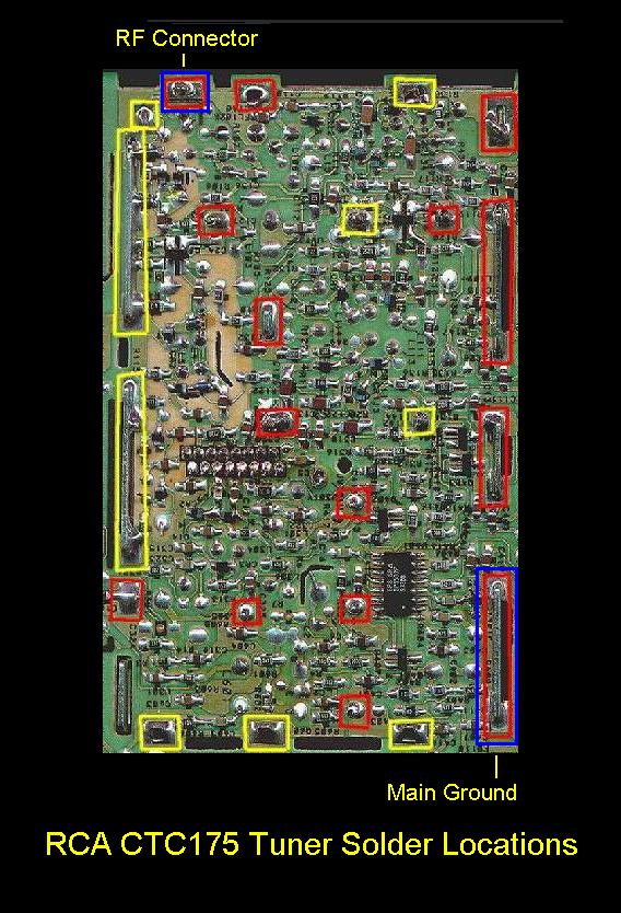
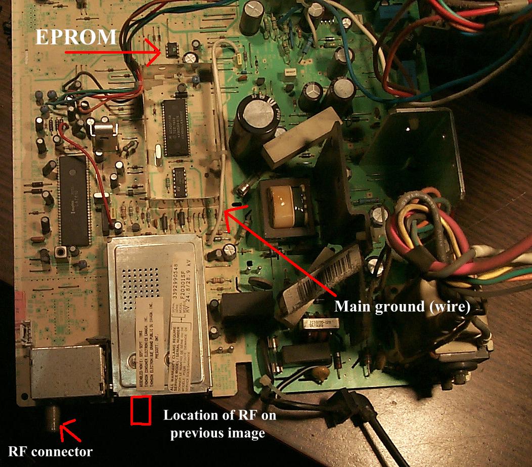
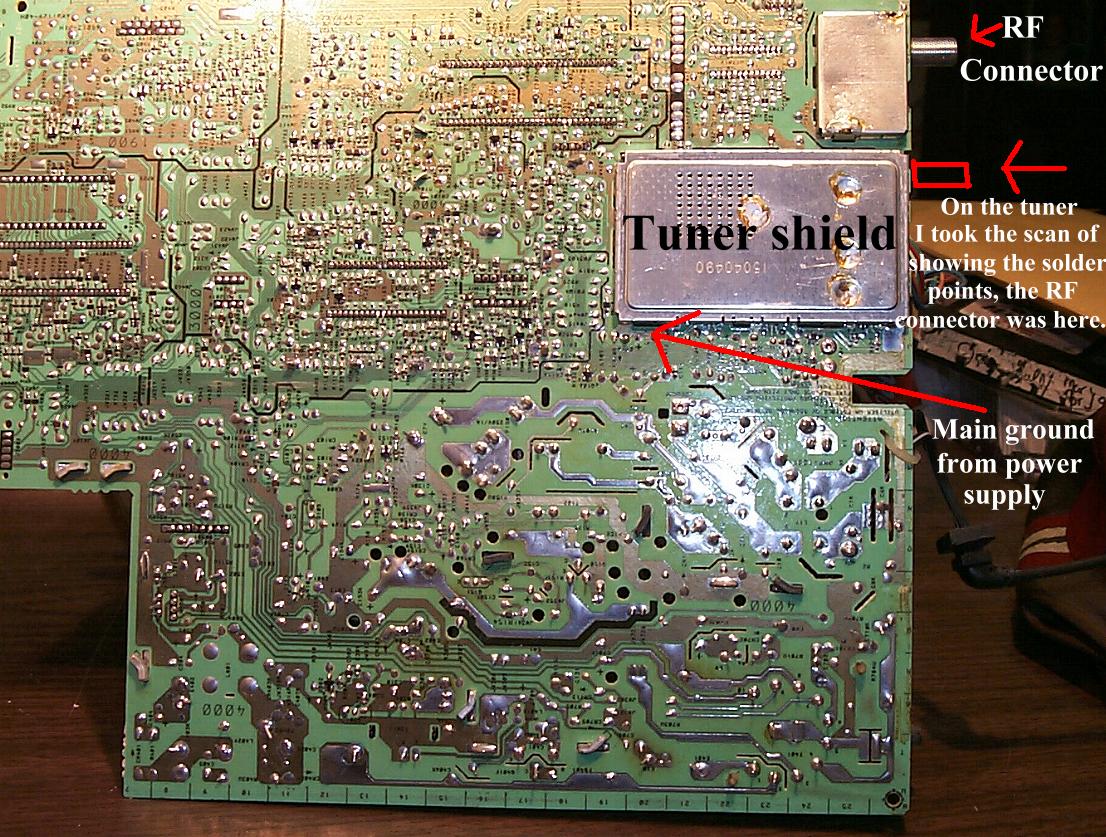
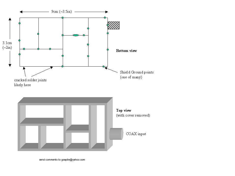