Sam's Interferometer Measurement Display System 1 (SG-MD1)
Installation and Operation Manual
Version 1.31 (30-May-16)
Table of Contents
SG-MD1 is a 5.5" x 4" PCB that attaches to the REF signal from an HP/Agilent
or similar two-frequency laser, and the MEAS signal from an optical
reciever through an interferometer returned from a movable retro-reflector
(mirror or cube-corner), and provides a visual
readout of position change in increments of the wavelength of light at
632.8 nm. The intent of this system is to be used to demonstrate
the principles of precision measurement based on two-frequency laser-based
interferometry.
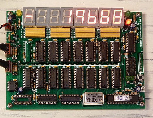
Photo of SG-MD1 PCB in Action
In a nutshell, the two-frequency laser sends out a pair of superimposed
beams that differ in frequency by a relatively constant amount (called
REF), one polarized horizontally and the other polarized vertically. Optics
separate the two beams sending one to a (generally) fixed reflector,
and the other to some tool or device whose position needs to be
measured precisely. Both beams then return to an optical receiver
where the difference frequency (called MEAS) is generated. With no
movement, the phase relationship between the two beams is constant and MEAS
equals REF. But if the tool or whatever moves, the frequency and thus
phase relationship between REF and MEAS will change due to doppler shift.
A phase change of 360 degrees represents a position change of 1/2
wavelength of the light from the laser, approximately 632.8 nm for
the HeNe lasers most often used. The precise wavelength is nominally
632.991372 nm with a wavelength accuracy of 0.1 ppm for the typical
HP/Agilent laser.
Using the two-frequency approach rather than a basic Michelson or
similar interferometer, among other things makes these systems
more immune to misalignment by eliminating issues of fringe counting
and direction, and fringe contrast.
In the diagram below, SG-MD1 replaces the "Signal Processing" block
and provides a means of demonstration the basic principles of
precision measurement using two-frequency laser interferomtery.
Aside from the low cost, this also allows for much more hands-on
since the schematics are available and all signals are accessible
for monitoring.
SG-MD1 is conceptionally quite simple. It consists of dual differential
line receivers for REF and MEAS, edge detection, synchronizer, 8 digit
BCD up/down counter and display, UP and DOWN monitor circuit, and control PAL.
- Dual differential line receivers: REF and MEAS are applied to
the UA9639 (U2) with the resistor networks R1-R3 and R4-R6 used to
set input levels for either single-ended or differential operation.
The output of U2 should be TTL level squarewaves (approximately) for
REF and MEAS.
- Edge detection: The cleaned-up REF and MEAS signals
may be applied to a dual D-FF 74LS74 (U3) used to divide each by 2.
The edges of the resulting waveform now represent the locations
interest. By dividing by 2, the frequency of operation of subsequent
circuits is essentially halved as well. If the D-FFs are bypassed,
the resolution is doubled (smallest increment is halved). More on
this below.
- Synchronizer: The first stage of the 8 stage 74LS164 shift
registers (U4 and U5) synchronize the REF and MEAS edges with the system
clock. The next 7 stages are used to reduce the probability of metastability
to less than 1/(age of Universe). :) The metastability isseu is the
possibility that the asynchronous edge will be sampled precisely when
it is changing, resulting in indecision in the sampled result. This
can produce a voltage in between legal TTL levels which persists for
a time much longer than the propogation delay specifications of the
flip-flop inside the shift register. This phenomenon is not generally
taught in Intro to Logic courses but can be responsible for infrequent
but catastrophic failures in logic systems. It is a fundamental
consequence of the uncertainty prinsiple and can never be eliminated
entirely. But with 7 additional shift register stages,
the chance of this bogus level making it to the subsequent logic
is minimized.
If it could be guaranteed that REF and MEAS edges would never be coincident,
the synchronizer wouldn't be needed and the up/down counter could be
driven directly. However, nearly coincident pulses to the up/down counter
would result in unpredictable behavior - counts could be dropped, extra
counts could be introduced, and the counter could even count incorrectly.
Since REF and MEAS are locally asynchronous based on the motion of the
remote retro-reflector or mirror, the relative timing of the edge is
totally arbitrary.
- 8 digit BCD up/down counter and display: U21-U28 (74HC192
BCD up/down counter with separate Up and Down clock inputs),
U31-U38 (74LS47 seven segment decoders), and U41-U48 (high brightness
orange seven segment LEDs) provide this function.
- Up and Down monitor circuit: The dual monostable (U7, 74LS123)
drives Up (green) and down (red) LEDs. The respective LED is pulsed
only when 2 Up or Down pulses occur in a row. This elminates the constant
activity that would otherwise be present.
- Control PAL: U6 is the magic sauce that drives everything else. :)
The logic inside U6 looks at the REF and MEAS edges and converts these
to Up and Down pulses to the counter and monitor LEDs. Depending on mode,
it may suppress strictly alternating Up and Down pulses to eliminate
activity in the display when the position isn't changing. Simultaneous
Up and Down pulses are always suppressed. It also
provides the proper signals to implement signed-magnitude mode in the
unsigned BCD counter including the Sign Overflow bits.
Depending on the objectives, an interferometric measurement system can be
put together from commercial or home-built components. The
latter would have an accuracy and precision virtually equal to that of
the commercial version but would have a net cost that is a small fraction
of it, and would have potentially much greater educational value.
Note that some basic soldering/assembly skills will be needed to wire up
the cables to the power supplies, laser, optical receiver, and SG-MD1.
If that capability is NOT available, then consider a complete system
with SG-MD1 included instead.
In addition to the SG-MD1 PCB, the following must be provided:
- DC power supply: Either a lab supply, a linear or switchmode wall
adapter can be used, or something else that produces 5 VDC at 1 amp
or more. But it must be regulated with an allowable voltage range
under load of 4.75 to 5.25 VDC. If in doubt about the regulation,
measure the output of the candidate power supply with no load. A
regulated supply will read close to 5 VDC even with no load, but a
typical unregulated wall adapter might read 50 percent high - or more.
Note that while some lasers provide a 5 VDC output, this likely does not have
sufficient current capacity, so a separate 5 VDC supply will probably
be required.
There are two power connectors on the PCB. While either one can power
the unit alone, it is recommended that power be attached to both to best
distribute the current. Cables with suitable connectors already
attached are included with SG-MD1. Double check polarity before applying
power! The PCB is reverse polarity protected but your power supply will
see a near-short circuit if wired backwards!
- Two-frequency HeNe laser with a beat frequency between 100 kHz and 4 MHz.
The easiest laser to use would be a Hewlett Packard (HP) or Agilent 5501A/B,
5517A/B/C/D, 5518, or 5519A/B, with the standard cable for power and REF.
However, it's also possible to use an Excel laser (which should be
functionally equivalent) or even a Laboratory for Science or some
other similar laser instead. Zygo may also have a suitable laser, though
the ones I'm aware of have a beat frequency that is way too high.
Or, you can build the equivalent using a short random polarized HeNe
laser tube, magnet(s), and simple stabilization electronics. See the
chapters: "Commercial HeNe Lasers" and "Home-Built HeNe Laser". Such a
laser would be nearly equivalent in performance to a $10,000 (new price)
HP or Agilent model.
The laser must provide a well collimated beam with the two frequency
components linearly polarized, orthogonal to each other, and aligned
with the horizontal and vertical axes. The required output power will
depend on how the REF and MEAS signals are obtained. For HP/Agilent
optical receivers, it can be under 25 microWatts (uW). So, even a
laser that doesn't meet the HP/Agilent specifications of 120 or 180 uW
can be perfectly suitable. To get decent range and signal from the
optical receiver(s), the beam should be expanded and collimated to
around 5 mm or larger. The commercial lasers will already do this,
but for a home-built laser, a beam expander will probably be necessary.
The local and remote return beams would have different wavefront
curvature and size unless the path lengths are close to each-other.
This would greatly reduce detected (MEAS) signal level, if one could be
detected at all.
Commercial two-frequency lasers are readily available on eBay at a small
fraction of their new price. A laser that starts and locks reliably,
even if it has low (below HP/Agilent spec) output power would be satisfactory.
If possible, obtain the mating cable for your laser as these are
generally rather special. But "hot wiring" directly inside the laser
is also possible. It's only 3 wires for power and 2 or 3 wires for REF.
These lasers typically run on +/-15 VDC. Check the requirements and
obtain appropriate power supplies. They don't need to be from the
laser manufacturer. Any regulated power supply that has sufficient
current capacity should work.
- Source for REF: The HP/Agilent lasers provide this output as a differential
pair that can be attached directly to SG-MD1. But a non-polarizing
beamsplitter to sample a portion of the laser beam, with an HP/Agilent
optical receiver could also be used if the laser doesn't provide REF
internally (as when using a very weak laser). Or rather than a commercial
optical receiver, a polarizer at 45 degrees, silicon photodiode, and
resistor can be used instead to produce the electrical REF signal.
However, non-standard resistors on the REF input to SG-MD1 may be
needed to accomodate your voltage levels.
- Interferometer optics: These can be any of the configurations discussed
in the chapter: "Laser Instruments and Applications". The simplest would
be a so-called "linear interferometer" with remote retro-reflector
(cube-corner). Either a commerical (e.g., HP/Agilent 10702A/10703A)
or home-built version made from a large polarizing beam splitter and a
pair of conrner-cubes can be used.
- Optical receiver for MEAS: A commercial unit like the HP/Agilent
10780 (any version) is easiest. (A 10780F/U will require a polarizer at
45 degrees if used without the fiber-optic cable and remote probe.)
But as with REF, a home-built receiver using a polarizer, silicon
photodiode, and resistor. will also work.
- Stable platform: The laser, interferometer optics, and optical
receivers should be mounted on a stable platform. Optimally, this would be an
optical table or optical breadboard. But, I've literally used a wooden
butcher-block with good success. Since these components don't need to be
changed once they are set up, shims can be used to fine tune heights and so
forth. If a metal base is used, HP/Agilent optical receivers should be
mounted using Nylon screws to avoid ground loops.
The remote retroreflector can be on a voice coil positioner (e.g.,
a loudspeaker woofer), a micrometer adjusted linear slide, or some other
means of precise linear motion. Or, attached to your favorite CNC
machine tool. :)
Seven two-pin headers set up SG-MD1:
- Signed-Magnitude Select (SGNMAG, JB1): Open for Signed-Magnitude,
installed for unsigned.
- No Single Count Oscillation Suppression (NOSCOS, JB2): Installed to
disable Single Count Oscillation Suppression (SCOS). Note that having SCOS
enabled will result in 1 count hysteresis on the measurement output but
less activity on the display if the position isn't changing. SCOS is always
applied to the UP and DOWN monitor LEDs.
- Leading Zero Suppression (LZS, JB3): Installed for leading zero
suppression. (Must be installed if using Signed-Magnitude mode.)
- D30 (JB4) and D28 (JB5): 4,000,000 and 1,000,000 initial
count for RESET. Open for "1". D30 MUST be 0 in Signed-Magnitude mode.
- Lamp Test (LT, JB6): Install to force all segments on. With
reliable LED displays, the main use of LT may be to check maximum power
supply current!
- Resolution (RES, JB7): This jumper determines
whether only the rising edge (X1), or both edges (X2) of the REF and MEAS
signals are used in the position determination. Install for X2. Using X2
will produce correct results on average, but may be more sensitive to jitter
from a weak MEAS signal.
The connectors on the SG-MD1 PCB are:
- Power (J1 and J5, 2 pin, +5 VDC at 1 amp max.): As noted above,
attach the power cable provided to your regulated DC power supply.
- REF (J2, 4 pin): Pins 1 and 4 are the differential inputs;
pins 2 and 3 are ground.
- MEAS (J3, 4 pin): Pins 1 and 4 are the differential inputs;
pins 2 and 3 are ground.
- External Control (J4, 8 pin): This provides an external RESET
input as well as outputs several useful signals:
   Pin   Function    Comments
 --------------------------------------------------------------------
    1    GND
    2    RESET_L     External reset (low asserted)
    3    GND
    4    MONCLK_P    Negative going pulse to monitor LED monostables
    5    UP_H        High during clock cycle counter is to go up.
    6    DOWN_H      High during clock cycle counter is to go down.
    7    OVFLQ_H     High if overflow in Signed-Magnitude mode.
    8    NC
- Counter Output Header: This is a 40 position set of pads which
will accept a SIL header to monitor the 32 bit output of the counter
(8 digits or 7-1/2 digits plus sign). It includes several ground pins
as well. Since these signals are not buffered, it is recommended that
wiring length be minimized to minimize the chance of peculiar behavior.
   Pin   Function   Pin   Function   Pin   Function   Pin   Function
 ---------------------------------------------------------------------
    1      GND       11     GND       21     GND       31     GND
    2      CQ1       12     CQ9       22     CQ17      32     CQ25
    3      CQ0       13     CQ8       23     CQ16      33     CQ24
    4      CQ2       14     CQ10      24     CQ18      34     CQ26
    5      CQ3       15     CQ11      25     CQ19      35     CQ27
    6      NC        16     NC        26     NC        36     NC
    7      CQ5       17     CQ13      27     CQ21      37     CQ29
    8      CQ4       18     CQ12      28     CQ20      38     CQ28
    9      CQ6       19     CQ14      29     CQ22      39     CQ30
   10      CQ7       20     CQ15      30     CQ23      40     CQ31
The only user control is the RESET button. :-)
The main readout is an 8 digit high brightness orange seven segment
LED display.
- In unsigned mode, the entire 8 digits (99,999,999) is available
for position measurement. This results in a totally ridiculously
high range of 30 meters with a single beam or linear interferometer.
or 15 meters with a plane mirror interferometer.
- In signed-magnitude mode, 7-1/2 digits (+/-19,999,999) are available
for position measurement. This results in a
range of +/-6 meters with a single beam or linear interferometer.
or +/-3 meters with a plane mirror interferometer) The "-" segment
of the MSD is used as the sign.
A yellow OVERFLOW LED will be turned on should the count exceed the
allowable range of +/-1,999,999. Once overflow is detected, the display
resets to 0 and won't change until the RESET button is pushed or the
RESET_L line on J4 is asserted. However, the monitor LEDs will continue to
function.
The UP (green) and DOWN (red) monitor LEDs provide a rough indication
of measurement activity. Each of these are pulsed on by a retriggerable
monostable when an up or down pulse is generated. Note that the activity
of these LEDs is independent of the setting of the NOSCOS jumper - they
always only show activity that isn't strictly altnernating up and down.
In other words, two successive MEAS pulses without a REF pulse is required
for the UP LED to pulse, and two successive REF pulses without a MEAS pulse
is required for the DOWN LED to pulse.
Note that when changing very slowly, both LEDs may sometimes come on
simultanenously even if the counter seems to be strictly incrementing
or decrementing due to even slight jitter in the REF or MEAS signals,
and unequal high and low times, especially if using X2 resolution.
The default pulse width for the monitor monostables is about 1 ms,
so counts in the range of 0 to 1,000 per second will result in a roughly
linear variation in brightness. This can be altered by replacing C1 and C2
with different uF values, which may be desirable if motion is mostly very
slow or very fast.
The resolution determines both the minimum detectable incrment in
position as well as the maximum range before overflow or wraparound
on the display.
- Interferometer optics: Using a plane mirror interferometer
doubles resolution compared to the linear or single beam interferometer.
- Resolution jumper: Doubles resolution if installed.
- Edge FFs: Bypassing the two flip-flips doubles resolution.
However, note that using the edge FFs doubles the maximum input frequency
for REF and MEAS. So, a system with a REF or MEAS frequency of up to
16 MHz and a |MEAS-REF| difference frequency of up to 8 MHz would work
correctly (if there is such a thing).
Any combination of these may be used but of course, increasing resolution
also reduces the maximum position change that cna be displayed (though I
doubt this is of much concern!). Also, higher resolution tends to
increase the effects of noise and jitter on display behavior at very slow
count rates and will mostly show up in the monitor LEDs both flashing
at low count rates. The recommended settings for SG-MD1 where resolution isn't
critical is to bypass the edge FFs but to leave JB7 open.
The inputs on SG-MD1 are to a dual channel differential line receiver. Each
input has an impedance of approximately 8K ohms (internal to the
chip). Positions for 3 resistors to set levels and sensitivity are
provided on the PCB. The more common configurations would be:
- Single-ended TTL: R1 (R4) = 1K ohms, R2 (R5) = 300 ohms, R3 (R6) = 500
ohms. Input is applied to pin 4.
- Differential (HP/Agilent optical receiver): R1 (R4) = open, R2 (R5) =
250 ohms, R3 (R6) = 500 ohms. Input is applied to pins 1 and 4.
The HP/Agilent signals can be used single-ended (e.g., only using REF,
not both REF and ~REF) but the noise immunity will be reduced.
Mini-coax or twisted pair is recommended for the REF and MEAS cables.
Note that the REF and MEAS channels are processed identically on SG-MD1 so the
only chnage resulting from swapping them will be to invert the direction
of counting. As labeled, UP is when the frequency of MEAS is greater than
REF.
Any of the interferometer configurations can be used with SG-MD1. These
are shown in:
What optical components are available will influence which configuration
is most appropriate and easiest to implement.
Some options for the "Tool" in a demonstration system include:
- Micrometer adjusted linear stage: Check the accuracy of
your micrometer. :) This is certainly the simplest and most straightforward.
- Voice coil positions (loudspeaker woofer) with function generator:
Show how very low amplitude signals can be converted to motion and detected.
Or, use the loudspeaker as a microphone and detect sounds!
- Machine tool: Attach the cube-corner or mirror to the carriage
on your Southbend lathe or Bridgeport milling machine.
- CD (or DVD) drive sled: Use $$$$ equipment to monitor which track
is being played on your favorite CD! :)
A sample diagram of a configuration using a plane mirror interferometer
and voice coil poisitioner with SG-MD1 is shown in:
The function generator provides a means of moving a mirror by a very small
and well controlled amount, with its signal monitored by an oscilloscope.
This could be done in a variety of other ways, including simply a micrometer
adjustmentable linear stage.
A version using a plane mirror interferometer is shown, because that
makes more sense for attaching to a loudspeaker than a bulky cube-corner.
And the butcher block version (pre-SG-MD1 using a frequency counter):
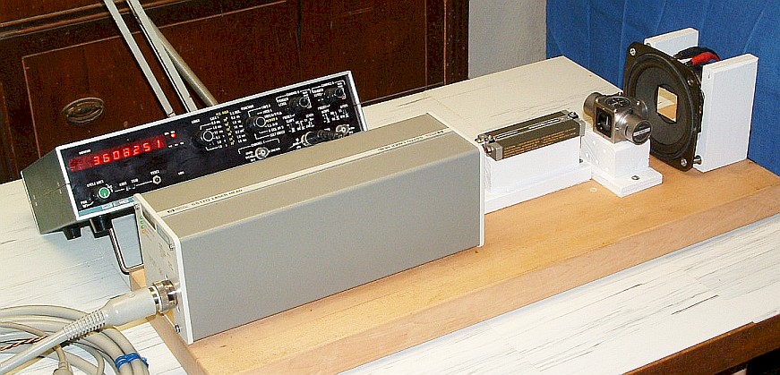
Photo of Two-Frequency Interferometer Laser Tester
Power the laser and optical receiver and wait for the laser to come READY.
- Once the laser and other components are in the general position of where
they are to be located, first align the laser beam with the interferometer.
For a single beam interferometer, the laser beam should be centered
within the clear aperture. For a linear or plane mirror interferometer,
it should be offset about 1/4 inch horizontally from the center, resulting
in a return beam for F2 (without the remote retro-reflector) of about
1/2 inch. This spacing is not critical as long as both the outgoing
and return beams aren't cut off. The interferometer and laser beam
axes should be aligned.
- Align the optical receiver (or photodiode) with the return beam.
There may be a detected signal even without the remote
reflector, especially if the laser is higher power (e.g., 400 uW).
This is due to imperfect coatings and imperfect alignment. Monitor
the signal level (there is a testpoint on the HP/Agilent recievers for
this) and fine tune the interferometer alignment to minimize it.
- Set up the remote cube-corner or mirror (as determined by the
specific interferometer configuration) so that its return beam
is precisely superimposed on the return beam to the optical receiver.
At this point, there should be s strong signal. If you have an oscilloscope,
it will be at the REF frequency of the particular laser and should
appear clean with minimal jitter.
For demonstration purposes, the reflector can be relatively close to
the interferometer, but that is not required. It would certainly be
more dramatic to have it across the room! However, for larger distances,
the quality of the cube-corner or mirror may be more critical. And,
vibrations caused by HVAC or a bus down the street will show up in
the readout!
With genuine HP/Agilent optics, it's very easy to get all this working
together. Even modest misalignment can be tolerated, though the
signal quality may degrade somewhat. Once everything is aligned,
make sure it's all locked down. Except for the remote reflector
(cube-corner or mirror), nothing else should move!
Once the laser, optics, and optical receiver are set up, it's time to
connect SG-MD1.
- Check/set jumpers on the SG-MD1 PCB. Default would be JB3, JB4, and
JB5 installed. This selects signed-magnitude mode that will reset to 0.
Do NOT plug in REF or MEAS just yet.
- Check the power wiring. Make sure the polarity is correct and your
5 VDC power supply is adequate.
- Configure the input resistors for REF (J2, R1, R2, R3) and MEAS (J3,
R4, R5, R6).
- Power up SG-MD1 and press the RESET button. (There is no automatic
power-on reset.) The display should show a "0" in the LSD. Make sure
the laser is READY before proceeding.
- Plug in the REF cable. The display should count down at a high speed
(the REF frequency) until the OVERFLOW LED comes on and it resets to 0.
- Plug in the MEAS cable and then press RESET again. The OVERFLOW LED
should go off.
- If the laser is READY and the interferometer is properly aligned,
the display should not change except for at most a few counts due to
vibration. Tapping on the table or doing almost anything else should result
in some activity. If the UP (green) or DOWN (red) LEDs come on bright:
- Full UP: There is no REF input. Note that prior to the laser locking
(READY off or flashing), UP will flash periodically with
corresponding rapid counting while the laser is initializing.
The OVERFLOW LED will come on eventually. But if the laser is READY
and there is still unexplained full speed counting up, check wiring to the
REF output of the laser. If your laser is very weak, the internal REF
signal may not be present. (The REF detect circuit may have been disabled
with the detect bit set to ON.) Also check the REF configuration resistor
values and wiring.
- Full DOWN: There is no MEAS input. The most likely cause would
be misalignment of the return beam in the interferometer, followed by
a wiring problem, MEAS configuration resistor values, or a defective optical
receiver or no power to it.
- Check that the display shows the expected change when the remote
reflector is moved.
Once proper operation has been confirmed, the entire system can be powered
at the same time. Then, when the laser comes READY, just press the RESET
button.
My present setup includes both SG-MD1 and an HP-5508A.
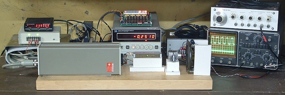
Photo of Sam's Interferometer Laser Tester with SG-MD1 and HP-5508A
From left to right are frequency counter on top of 5 VDC power supplies
for SG-MD1 and the buffer amp for the loudspeaker, SG-MD1 on top of the
HP-5508A, my power supply for 5517A lasers (presently unused), and
function generator on top of oscilloscope. The readouts differ both because
SG-MD1 displays half-wavelengths compared to the HP-5508A's microinches,
and they weren't initialized identically.
A large variety of problems can be caused by issues with DC power.
So, first check that the +5 VDC and GND connections are secure and that the
supply voltage is within +4.75 to +5.25 VDC from no load to max load.
Install the Lamp Test (LT) jumper to turn on all segments of the display
to get close to max load.
Most other problems are related to either REF and/MEAS signal integrity,
or interferometer alignment.
Some common problems and solutions:
- Symptom: No LEDs (display or indicators) on when power is applied.
- Symptom: Up (green) LED on solid.
- Symptom: Down (red) LED on solid.
- Possible cause: MEAS signal missing or input resistors (R4-R6) incorrect.
Solution: Check wiring, optical receiver, and its power supply. Use scope
to trace MEAS signal through differential receiver and correct input resistor
configuration if needed.
- Possible cuase: Interferometer misaligned or improperly set up.
Solution: Double check that interferomter configuration is correct.
Adjust alignment using optical receiver signal LED and/or test point
to maximize signal strength.
- Symptom: MEAS signal present even if remote optical path is blocked,
and no activity when retro-reflector or mirror is moved.
- Possible cause: Interferometer misaligned around optical axis or
improperly set up.
Solution: Double check that interferomter configuration is correct.
Adjust alignment using optical receiver signal LED and/or test point
to maximize signal strength.
- Possible cause: For higher power (e.g., 500 uW) lasers, this may be
normal due to unavoidable reflections from AR-coated surfaces. Once the
return beam is properly aligned, this will not be an issue.
Solution: Fine tune interferometer alignment. If this doesn't help, the
sensitivity of the optical receiver and/or laser power (using ND filter)
may be reudced to minimize confusion.
- Symptom: Excessive activity with remote retroreflector or mirror
stationary but average reading is accurate:
- Possible cause: Vibration resulting in optical path length changes.
Even a fan running in the next room or transit bus down the street may
be enough to produce detectable position variations.
Solution: Turn off unnecessary equipment and have the local Transit Authority
stop bus service while you're doing your experiments. :)
- Possible cause: Excessive jitter in REF due to interferometer
misalignment and/or a laser with amplitude oscillation, especially if the
laser is rather weak.
Solution: Check REF and MEAS signals with oscilloscope to determine if
excessive jitter is present. The normal REF and MEAS waveforms should
be almost perfectly clean. If any jitter is detectable, it should be
less than the trace width. Check and fine tune interferometer
alignment. If this doesn't help, power cycle laser and monitor MEAS for
evidence of a beat frequency around 700 kHz in between periods
of normal MEAS frequency. If present, this may be contributing to the
excessive jitter, especially if the lsaer is rather weak. The laser
may need to be refurbished. See the Lsaer FAQ, chapter on "Commerical
HeNe Lasers", for details.
- Symptom: Excessive activity with remote retroreflector or mirror
stationary and average reading is erratic.
- Symptom: No monitor LED activity and readout doesn't change even though
retroreflector or mirror is moved. This means MEAS is present but is not
changing.
If the solution to your problem isn't in the above list, performing the
following static logic tests on SG-MD1 will go a long way toward confirming
that it isn't at fault. In addition to the 5 VDC power supply, this will
require a pair of pushbuttons with debounced TTL-level outputs:
- Configure the resistors on the REF and MEAS inputs for single-ended TTL.
- Configure the jumpers as desired.
- Attach your debounced pushbutton outputs to the REF and MEAS connectors.
(Don't forget GND!)
- Apply power and press RESET. The display should read 0 or 00,000,000
depending on the settings of LZS and SGNMAG.
It may be desirable to install 10 uF capacitors across C1 and C2 so the
monitor LEDs will pulse for a longer amount of time with each count.
(For electrolytic caps, plus should be on pins 15 and 7.) However, the
~1 ms flashes using the default capacitors should be clearly visible under
reduced lighting conditions.
SG-MD1 is now running just as it would with the real REF and MEAS inputs
except that you are providing them manually!
- Pressing the MEAS pushbutton should result in the counter incrementing
by 1 count while pressing the REF pushbutton should result in the counter
decrementing by 1 count.
- Pressing both pushbuttons at the same time should result in no net
change. Of course, relative to the system clock (typically 10 MHz),
your presses will never be quite simultaneous but the effect will
appear that way!
- Depending on the setting of NOSCOS, the counter will behave differently
with alternating counts:
- NOSCOS=0: Strictly alternating pushbutton presses will be ignored
both with respect to counter activity and monitor LEDs.
(This is always the behavior of the monitor LEDs.)
- NOSCOS=1: Strictly alternating pushbutton presses will result
in the counter incrementing and decrementing by 1 count, but the
respective monitor LED will not flash.
- In signed-magnitude mode (SGNMAG with LZS), attempting to decrement
past 0 using the REF pushbutton will result in the sign changing to
negative and the counter incrementing, and continuing to increment after
that with repeated REF presses. Pressing MEAS will then reverse this.
Tests of other configurations should be self evident.
If none of this is able to identify the problem, it may be necessary to use an
oscilloscope to probe the internal signals.
The following assumes that the RES jumper is set for X2 and the edge FFs
are present. Different settings will change the maximum measurement range
in an obvious manner. Also see the section on "Selecting resolution", above.
- REF and MEAS inputs: Single-ended or differential, 5 V p-p max,
compatible with TTL, CMOS, and other common logic signal levels.
- REF frequency range: DC to 8 MHz subject to |MEAS-REF|< 4 MHz.
- MEAS frequency range: DC to 8 MHz subject to |MEAS-REF|< 4 MHz.
- Display format: 7-1/2 digit 0.56 inch LED signed-magnitude
(0 to +/-19,999,999 or 8 digit unsigned (0 to 99,999,999 representing
number of complete cycles of position/change at 633 nm. PCB may be
underpopulated for reduced range.
- Maximum measurement range: In
signed-magnitude mode, equivalent to approximately +/-6 meters (linear
or single beam interferometer) or approximately +/-3 meters double
resolution (plane mirror interferometer). In unsigned mode,
30 and 15 meters, respectively.
- Leading zero suppression: Enable or disable. (Must be enabled
for signed-magnitude display.)
- Single count oscillation suppression: Enable or disable.
- Data output: Header location provided for all counter bits.
- Activity monitor: Green (up) and red (down) LEDs whose brightness
is proportional to rate of count.
- Error indication: Signed-magnitude overflow forces counter to
zero and turns on yellow overflow LED. Sign indicates direction of overflow.
System must be reset to clear error.
- Initialization: Reset via on-board pushbutton. Initial value
selected by jumpers may be 0, +10,000,000, +4,000,000 or +50,000,000 (the
last two valid in unsigned mode only).
- Jumpers: Unsigned, no single count oscillation suppression,
leading zero suppression (must be on for signed-magnitude mode), lamp test,
resolution.
- External control: Input: Reset (low); Outputs - up, down, monclk,
overflow (signed-magnitude only).
- Connectors:: Power, REF, MEAS, External Control, Data Output.
- Power requirements: 5 VDC at 1 A max.
- Size: 5-1/2" (Width) x 4" (Height) x 0.5" (Depth).
A prototype SG-MD1 has been built and tested. Some minor bugs were fixed
and Rev. 1.2 artwork is complete. SG-MD1 has been in extensive use in my
interferometer testing rig for several years. However, times change and the
µMD1 Micro Measurement Display using a microcontroller instead of
discrete TTL is infinitely better and easier to build. There are therefore
no plans to do anything further with SG-MD1. The End. :-)
Back to SG-MD1 Table of Contents.
-- end V1.31 --