Since some of these descriptions are quite long, this page has a Table of Contents:
(These photos, description, and questions are from: Daniel Ames (dlames2@aol.com).)
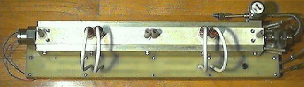
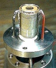
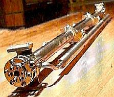
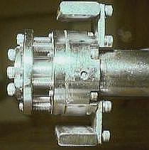
I have a laser of the waveguide type, but I really don't have a clue as to it's operating parameters, since there is not any info attached to this laser except: IO255-515 on the optics mountings and written in pencil on the bottom of the ceramic cavity is (DEA). Not to be confused with (TEA).
It is has very strange optics - a total of 5 of which 4 all look the same, color-wise.
Additional Notes:
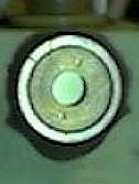
Would it appear to be a thermocouple to sense the lens/mirror temp?
What I don't understand is that if I leave the Digital meter hooked up to this part, the reading does not stabilize, instead, the millivolt reading will eventually (zero).
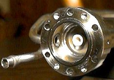
If the two mounted to the "cavity" were clear, or at least different, then I would tend to think these two are only "windows" and the outer two would be the OC and HR mirrors. But they are all visibly the same! haaaaaaha!!!!!!
Please email me with any questions or answers.
Thank you for your time and comments concerning this unique laser.
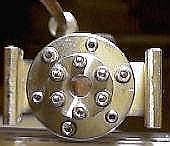
My guess is that is IS a CO2 laser that is non-RF excited. The 0.5 M resistors are consistent with ballast for a CO2 laser. Their 100 W power dissipation rating suggests a current through each set of electrodes of around 10 to 15 mA which is consistent with a bore size of 2.5 mm square.
The windows and mirrors are probably ZnSe but with the thickness of the AR and reflective coatings used at 10.6 um, visual inspection won't show much. So, heir characteristics could be quite different at 10.6 um.
Are you sure there isn't another gas connection? A sealed system would seem unlikely.
Here is a somewhat edited version of the discussion about this laser on the USENET newsgroup sci.optics:
(From: Mark W. Lund (mlund@moxtek.com).)
This is most certainly a carbon dioxide RF waveguide laser. Two windows seal the cavity and two mirrors make the cavity. The "DEA" is intriguing. Similar to TEA (transversely excited atmospheric pressure).
(From: Daniel)
The (DEA) markings, under the channel are similar to (TEA), I wonder if the DEA. is referring to a laser term, or maybe the federal agency (D.E.A.)???
(From: Harvey Rutt (h.rutt@ecs.soton.ac.uk).)
It looks as if it ***MIGHT*** be a waveguide carbon dioxide laser. These can use channels in alumina ceramic; some were made using beryllia based ceramics, so be careful if you open it, any dust just *might* be very nasty. If it is the output beam is almost certainly class 4 and definitely hazardous. 2.5 mm square is reasonable.
(From: Daniel)
That is what I first thought, but ~ since the optics are stamped (IO 255-515), it would seem as though it's a CO2 waveguide cavity but used with some other gas or combination of gasses which would yield an output wavelength between 255 and 515 nm. if these IO markings actually do indicate its operating wavelength.
(From: Harvey)
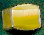
I think this is just a catalogue number; I can't think of any waveguide laser at these wavelength, and getting 255 nm and 515 nm together would be tough. If the mirror substrate is orange ZnSe (see later) that rules it out.
The entire channel, looks like (beryllia based ceramics)!!! Do you know of any type of "sealant" that can be applied to the outer surfaces, in order to make the beryllia safer or is really unnecessary? All 4 sides of the cavity, actually the whole channel assembly is ceramic.
(From: Harvey)
No, no sealant that would still be usable. It is more likely alumina, but it *might* be beryllia. If so you really should be careful; inhaled beryllia dust is really very nasty (solid lumps are pretty safe.) Trouble is you cant easily tell, so take care. I am no safety 'freak', & often people go over the top; but beryllia dust is a real nasty hazard.
That suggests DC excitation to me; a lot of RF ones used transverse excitation, but I *think* there were axial RFs too. More modern ones are mainly RF driven.
(From: Daniel)
I agree, but I am currently unfamiliar with the features of RF excited lasers. Since this one has a separate (.5 M ohm) resistor on each unshielded HV wire, would this rule out the RF excitation???
(From: Harvey)
Yes, that makes it DC for sure, fits the other info.
Some used a Z fold cavity with fixed mirrors at one or more fold. Some had a hermetic ceramic cavities, some the ceramic block in an outer vacuum vessel, which this would be.
(From: Daniel)
If I understand the idea of Z fold correctly, this does not appear to be a folded cavity. All (5) optics look like they are on the same axis as the single cavity.
(From: Harvey)
Do the mirrors look like germanium (opaque, steel like) or zinc selenide (orange)?
The 70% on one end would be reasonable for CO2, bit low for single pass of that length though. Looks like one mirror may be external; is there a Brewster window? If so, of what?
(From: Daniel)
Four of the 5 optics look exactly like (ZnSe opaque orange).
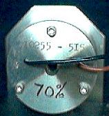
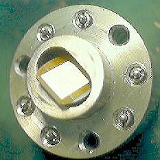
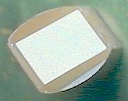
There are no Brewster angle windows, the two optics that seal the cavity, are perpendicular to the axis of the cavity's bore. The 65% which is hand written on both the front and rear adjustable optic assemblies is very puzzling. I don't actually know if that is referring to the original reflection %, or if it is referring to what these optics are rated at now, after many hours of use.
(From: Harvey)
That pretty much proves its CO2. Possibly they changed the coupling; but 65 to 70% does seem a bit low if it's oldish, that length, and not folded.
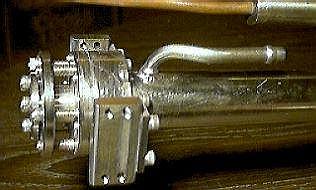
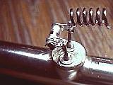
The end with a cylinder with 2 wires *might* be a piezo or electromagnetic drive to tune the axial mode.
(From: Daniel)
Piezo or electromagnetic drive? Now that is something I know nothing about. How would you suggest for me to actually determine if it is a piezo-opto or electric drive?
(From: Harvey)
If its piezo it will be very high resistance, quite high capacitance, and need 100's to low 1,000's of volts to drive it & very little current (except to charge the C of course.) If electromagnetic, low resistance, considerable inductance, & need a few volts at fair current. Measure its electrical characteristics & see which one fits.
(From: Daniel)
Using a DMM, on the auto ranging ohms setting, it read (OL) as if it was "open", but on the millivolt setting, I did notice that it's readings are very active and very sensitive to minute temperature changes. Does this mean anything??
(From: Harvey)
Almost certainly a piezo drive.
(From: Daniel)
Sorry, but I do not have a meter that can read inductance and capacitance. I have two of these lasers, both exactly the same except the optics are marked 65% on one laser and 70% on the other, so I tested the "drive?" on the other output coupler assembly, same results.
But that's odd; you usually only have them on *one* mirror.
So this would lead me to believe that it is in fact, most likely a piezo opto/electric drive.
(From: Daniel)
But for one thing: The two wires connected to it, (1 red and 1 black) are definitely not high voltage type wires (approximately AWG 18) and pass through the stainless adjustment plate for the OC without any HV insulation, except for the very thin insulation on the wires themselves. Very interesting. Now I am really puzzled....
(From: Harvey)
Voltage might be a few hundred to 1 to 2 KV, so ordinary wire would do.
(From: Chris Chagaris (pyro@grolen.com).)
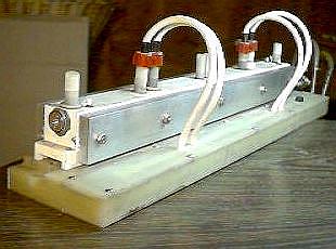
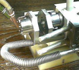
All right my friend, this laser of yours is driving me crazy! I've been studying the photos and re-reading your descriptions.... and losing sleep. :-) I assume the copper lines with the hoses attached are the water lines. I notice what looks like two stainless (?) lines also attached to one end. Are these gas ports?
(From: Daniel)
No, the stainless steel lines, 2 on each side, are actually for the aluminum (water) cooled heat sinks for heat dissipation of the ceramic channel.
(From: Chris)
What are the flexible line? Have you disassembled this unit??? I've got to get a peak at the innards!
(From: Daniel)
No, I don't want to attempt disassembling the channel as it is 100% ceramic, possibly BeO and inhaling (hazardous beryllia dust) is something that I really don't wish to add to my menu. Also, the entire channel is epoxied (type, unknown) together using thin 3/16" ceramic pins for alignment. But I must add, my curiosity of the design of the electrodes, etc., is quite strong as well. Hopefully, I will be able to find some more detailed information in some journals soon.
(From: Chris)
You say that there are resistors connected to the electrical connections? This would, I think, rule out a waveguide laser.
(From: Daniel)
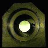
Actually, some waveguide lasers are, or at least were, DC excited. An interesting point about this laser is that the inside walls of the 2.5 mm ceramic cavity are highly polished and extremely reflective.
(From: Steve Roberts (osteven@akrobiz.com).)
That is a waveguide CO2, a similar one is setting at a surplus place near here. It is quite normal for small CO2 lasers to have non-adjustable parallel windows instead of Brewsters. Some of the ones I see are just salt disks glued on at random using RTV Silicone, even in a 45 watt unit. I see it all the time on the flowing gas medical units I resell. The gain of CO2s is so high compared to most common visible lasers that you can get away with a lot of things you'd never dream of doing, with say a argon. The ZnSe does have it but they will usually look the same in visible light, as they are rather thick compared to a normal multilayer visible coating.
(From: Daniel a couple weeks later)
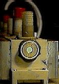
Well, I just pulled off the optics mounting behind the HR mirror - curiosity was too much. And guess what I found? - some type of diffraction grating. Normally, you put a diffraction grating inside a laser cavity to provide some sort of tuning capability. OK, I have heard of tunable CO2's, but I am totally in the dark, (no pun intended) about why this grating reflects depending on the angle tilted or viewed, it reflects the visible wavelengths (red - violet) if this is a visible laser, then this would of course be normal, but for a CO2 laser operating in the IR? Brings me back to one of my original questions: It looks like a CO2 waveguide laser, but the elaborate OC & HR optics mountings are stamped: I0255 - 515.
There are only three possibilities at this point in time that I can think of:
Since I am definitely not a CO2 laser expert (of any type), the above comments are only my possible conclusions and not to be interpreted as "The CO2 Gospel".
(From: Sam)
Can you what type of material is used for this, err, grating?
(From: Daniel)
You know, that is a really good question, so I just managed to find a way to remove it for inspection. Guess what? It has a threaded stainless steel insert for mounting or replacing and it is a solid wedge (like a 90 degree prism) of GERMANIUM, "Ge" is even written on the bottom and it is definitely the same color as a (2") germanium OC that I have. However, the grating surface looks like it has a thin film deposited on it, gold in color when viewed outside of the normal reflection angle and when viewed through a diffraction grating it does reflect all the visible colors, maybe IR as well, but I am not set up to check that.
(From: Daniel)
I wonder if there is any info anywhere on aligning a laser of this type. I tried it today for the first time!!!!!!
Wow, it seems to be quite different than aligning a standard laser. The internal side of the (square) cavity, are sooooooooo, reflective, that if you are off, even just a micro hair, you can get many spots, I was getting (12) in a very nice rectangular grid like pattern, then after continuing to adjust them, it turned to something you might see on Star Trek for a (red plasma cloud) and much optical interference patterns of the same. Makes a great lighting effect, but that's not the goal. :(
(From: Sam)
I assume you are using your HeNe for alignment? What is the setup? Just passed through to align with waveguide and looking for reflections back to the source for mirror alignment? I guess if one mirror were removed, you could slide an opaque plastic tube down the bore to act as a normal bore but with them both in place, don't know other than just perseverance until you get a single spot (or die from old age).
I wonder why the inside of the bore is so highly polished. This would result in not only the difficulties in alignment that you observed, but also the tendency for the laser to operate in all sorts of axial modes at the same time.
(From: Daniel)
About the (CO2) waveguide's electrodes. I noticed that two of the electrodes, which are just glued in place, were loose, so I took them out. One anode and one cathode. I am surprised as to how small they are - about 1/16" in diameter by 3/16" long, like a small pin. The anodes are hollow and look like a redish brass (more like a phosphor/bronze) and the cathodes (closest to the ends of the tube) are like solid pins and look like either nickel of stainless steel. Interesting... Given this description, can you surmise as to whether this laser wants AC or DC continuous or DC pulsed, RF, or what?
The cathodes as I will refer to them as, are so small, even smaller in diameter than the anodes (the ones with the high voltage wires in the photos) This doesn't make sense to me.
Any suggestions, hints, etc., would greatly be appreciated, as I don't want to fry these tiny electrodes.
(From: Sam)
That's (once again) weird.... We've been assuming they are anodes and cathodes but nothing actually says that, correct? Normally, most of the heat is dissipated at the cathode - could they actually be mounted in a much larger block of metal or could the BeO or whatever be acting as a heat sink?
(From: Daniel)
No, there is nothing on these lasers which actually specifies anodes and cathodes.
They don't seem to be attached to anything else, inside the cavity. I powered it up (for evaluation only) using a 7.5 kV @ 30 ma, fully rectified supply with just CO2 and He. The optical (opaque) transmitting properties of the cavity material are such that you can actually see not only where the ionization is, but it's color too. Within the 4 discharge sections of this tube, the cavity ionizes right up to the electrodes and since all 8 electrodes are connected to the top of the cavity, it would appear as if they are the actual electrodes.
The beryllia most likely does dissipate some heat from the cathodes, but the surface area of the cathodes and anodes that actually fit through the hole and tight against the cavity material, plus the 5/16" diameter by 3/32" thick base of all 8 electrodes is so minute, that it would seem to be minimal.
(From: Sam)
Given that there IS a difference between the electrodes, I doubt it is AC.
Given that there are ballast resistors and no shielded wires, I doubt it is RF.
So that leaves DC or pulsed DC. Don't know. Strange and all that. :) Again!
(From: Daniel)
I agree, I would tend to believe it not to be AC for a couple of reasons:
I also agree that it is not likely RF excited, based on these same facts, plus, for another test: I hooked up a HeNe power supply rated at 2.5 kV @ 6.5 mA. The negative was hooked to the 4 original hypothetical cathodes and the positive to the the 4 hypothetical anodes. Don't try this at home, kids. Even with enough gas pressure to all but extinquishes the ionization, the entire laser, (all the metal parts) became electrically charged as if it was all hooked up to a high powered Tesla coil. Zapp! - here there and everywhere! So, for this reason, I definitely agree, that there is no way, not even remotely, that this waveguide co2 laser could be R/F excited.
Recently, I was reading up on gas lasers and related power supplies in the Laser/Electro-Optics Technology curriculum developed by CORD.
(From: Sam)
All links to the CORD courses, below, are to my copy of this material Sam's Copy of LEOT Material since the links to the CORD Web site are no longer working.
(From: Daniel)
In particular: Gas Lasers and Related Power Supplies.
They show many different types of laser cavities and electrode configurations, including a power supply for the copper vapor laser that is relatively simple and (does not) use the any spark gaps, of course, this design would have to be duplicated or modified to operate a Copper halide laser for the dual pulse.
Getting back to the CO2 waveguide, the closest electrode configuration I found there to this waveguide, is the (CO2 Pin laser) actually an early TEA design. The anode was a metal bar running the length of the cavity & the cathodes were actually "pins" with each one having it's own ballast resistor to balance out the discharge energy evenly to all the cathode pins.
So this got me to thinking, what if we actually have the anodes & cathodes reversed and the electrodes with the high voltage wires attached, are connected to the (4) separate ballast resistors, (which measure 2.5 x .5 x 0.5" at 0.5M ohms and wattage is unmarked) which we thought were the anodes, might actually be the cathodes which are the ones with the hollow, pin type electrodes, the others are a solid pin "with a round tip", which sounds more like an anode shape. (This brings up another consideration ~ CO2 catalyst? Where are they usually located and what do the look like?)
OK, so for instance, if this is the case and the (2) electrodes located at each end of the laser and very close to the stainless mirror mountings and the ZeSe windows, are actually the (+) anodes ~ this brings us to another consideration which is, now the two windows, the mirror mountings and the stainless flex tube and gas valve can become electrically hot, (high voltage and current) if touched when the tube is powered up. maybe if the gas pressure inside the cavity was just right and the exact right power supply, these external metal pieces could be grounded, but the cavity material, beryllium oxide does not seem to be very electrically insulative at this point.
(From: Sam)
On another note, I wonder why the inside of the bore is so highly polished. This would result in not only the difficulties in alignment that you mentioned previously, but also the tendency for the laser to operate in all sorts of axial modes.
(From: Daniel)
I am currently looking into different methods of alignment, since this waveguide not only has the standard OC and HR optics, but also two plano windows that are not at the Brewster angle, but instead they are perpendicular to the optical cavity. So I am getting reflections from the mirrors and the two windows, combine this with the dielectric reflections off of a square & narrow, highly reflective cavity (approximately 2.5 mm), Y2K might get here first, plus I am going to try a different HeNe with a narrower diameter beam. Maybe if I use a lens convex lens with focal length of approximately (3) times the length of the optical path from the image reflecting plate to the furthest mirror (HR), hopefully this will help in distinguishing the external spot reflections from the OC and the spot reflections that have actually passed through the cavity to the H/R mirror and back out the OC to the image reflecting plate, based on diameter.
If I understand the function of the (piezo/electric?) device on this laser correctly, that the OC is attached to, based on the info below and other related articles such as in some of the (80's) journals, Review of Scientific Instruments, the axial/longitudinal modes can be isolated and enhanced and Q switched, reducing unwanted axial modes and allowing the wanted mode, or modes to be amplified.
Waveguide lasers are specifically dealt in the CORD course at: Course 3, Module 9: CO2 Laser Systems, approximately 40% down the page). The following is a direct quote:
Waveguide CO2 Lasers"The opposite of the size extreme from the gas dynamic laser is the waveguide CO2 laser. These are small lasers with typical lengths of 5 to 25 cm and bore diameters as small as 1 mm. Bores of these laser tubes are made of beryllium oxide. The hollow dielectric structure acts as a waveguide for the CO2 laser light producing a low-loss optical cavity. The small bore diameter results in good gas cooling efficiency and high gain. Waveguide CO2 lasers produce output powers of around 0.2 W/cm of tube length. Thus, a laser only 10 cm long can produce an output power of 2 watts.
Waveguide CO2 lasers are rugged and dependable and are attractive for applications in communications, pollution monitoring, and optical ranging systems."
(End of quoted material)
Of course, the output power would be dependent on several factors such as, gas mix concentrations & pressure, type of mirror configuration and the transmitting % of the output coupler, type of ionization energy, DC continuous. DC pulsed, or RF and the method of cooling the cavity. Note, on these particular waveguides that we are discussing here, the output couplers have a high percent of transmission, laser 1 = 65% reflection, laser 2 = 70%. With this much transmission % of (30 - 35%), the output power increases drastically. I have not tested the laser in actual operation and with the electro/optic piezo/electric mode stabilizer/Q switch, but I would conclude that by the given O/C reflectance of (65 - 70%) combined with the low loss optical waveguide cavity and the piezo/electric mode stabilizer/Q switch, the output power could be relatively more than we anticipated at
There is a great deal of additional information in Course 4, Module 7: Electro-Optic and Acousto-Optic Devices. following is a direct quote:
Mode-Lockers"Within a Q-switched laser pulse there may be further substructure. This arises because of a phenomenon called mode-locking. If a number of longitudinal modes is present in the laser output, these modes may interfere and lead to an oscillatory behavior for the output. Thus, within the envelope of the Q-switched pulse, there may be a train of shorter pulses. If only a single longitudinal mode is present in the laser output, there will be opportunity for mode-locking.
In many lasers, a number of longitudinal modes will be present simultaneously. Ordinarily, the phases of these modes will be independent of each other. But under some conditions, the modes can interact with each other and their phases can become locked together. Then the behavior of the output will contain a train of short, closely spaced pulses within the Q-switched pulse.
Mode-locking may be accomplished intentionally by introducing a variable loss into the cavity, such as an electro-optic or acousto-optic modulator, so that the gain of the cavity is modulated at the frequency c/2L, which is the difference in frequency between adjacent longitudinal modes. Here c is the velocity of light and L is the length of the laser cavity.
In the time domain, the output of the mode-locked laser consists of a series of very short pulses. From a simple point of view, one may consider that there is a very short pulse of light bouncing back and forth between the laser mirrors. Each time the pulse reaches the output mirror, a mode-locked pulse emerges from the laser. The result is a series of short pulses separated in time by 2L/c, the round-trip transit time of the cavity. The duration of these pulses is very short, often of the order of a few picoseconds. Hence, a laser operating in this fashion is often called a picosecond pulse laser.
The mode-locking behavior is encouraged by inserting a modulator in the laser cavity near the output mirror and opening the modulator at a frequency c/2L. This is shown in Course 4, Module 7: Figure 14 - Example of a modulator used as a mode-locker.
The minimum duration for a mode-locked pulse is equal to D n , where D n is the spectral width of the active medium. For an Nd:glass laser, the spectral width is large, around 1012 Hz. The minimum pulse duration for such a laser is then around 1 picosecond. The shortest pulses that have been produced have come from liquid-dye lasers, for which the spectral width can be very large. Pulses as short as 30�femtoseconds (30 � 10- 15 sec) have been produced. This is remarkable in that the total duration of the pulse contains only a few cycles of the high-frequency electric field.
One may obtain a single pulse with this duration by using an output coupler such as an electro-optic switch that opens long enough to let one pulse emerge from the train of output pulses and then closes again."
Drivers for Electro-Optic Devices
"Electro-optic devices require relatively high voltages, typically of the order of kilovolts for longitudinal devices and a hundred volts to a few hundred volts for transverse devices. The power supplies that are used to supply them may be ordinary laboratory power supplies if the frequencies are not too high. Any power supply or function generator that can supply the required half-wave voltage at the required frequency will generally be adequate.
The Pockels cell represents a capacitive load, so the power dissipation is not excessively high.
If the frequency is high or a very rapid rise time is required, it becomes more difficult to switch the required values of voltage at high speed. One circuit that has been employed for driving Pockels cell modulators at high speed is shown in Course 4, Module 7, Figure 15: Drive circuit for electro-optic Pockels cell. This circuit uses a switching tube called a krytron. This is a gas-filled tube that has the capability of shorting out voltages in the 3- to 7-kilovolt range. The trigger pulse that initiates the operation of the switch is delivered through a silicon-controlled rectifier (SCR) and transformer. This circuit is capable of switching the Pockels cell modulator at speeds in the nanosecond range. The chief drawback of the circuit is the limited lifetime of the tube.
The manufacturers of commercial electro-optic light-beam modulators, deflectors, and Q-switches generally also supply a line of power supplies for their devices. The voltages and impedances of particular power supplies are matched to the requirements of individual electro-optic devices. The rise times for some of these voltage drivers may be less than one nanosecond."
(End of quoted material)
So, this may be a tunable (by adjustment of the diffraction grating) mode-locked (using the piezo actuator) CO2 laser. There are actually around 97 CO2 laser wavelengths in the 9 to 10 um range that can be selected based on cavity characteristics, gas fill and pressure, and excitation) mode.
(From: Stanislaw Skowronek (thesis@elementy.pl).)
The 'temperature sensor' is not a thermocouple. In fact, as far as I can tell, it is a pyroelectric sensor, a very sensitive one. It's very probable that it reacts to the long-wave IR radiation of CO2. Most commercial pyro sensors are sensitive to some 5 to 10 um light, light?!, uh, radiation, and are used in PIR burglar detectors ;). The 'decay' is very typical of them.
(End of discussion so far)
Here are the photos:
There is much more information on CO2 lasers in the Carbon Dioxide Lasers and Home-Built Carbon Dioxide Laser chapters of Sam's Laser FAQ.
(These photos, description, and questions are from: Daniel Ames (dlames2@aol.com).)
Here is another strange and interesting laser. To be honest, I really very little about this one. I don't even know if it really is for CO2 or CO!
Description:
And now for the good stuff:
As someone once said, aside from the unknowns, everything else is obvious (--- Sam). :)
Here are the photos:
There is much more information on CO2 lasers in the Carbon Dioxide Lasers and Home-Built Carbon Dioxide Laser chapters of Sam's Laser FAQ.
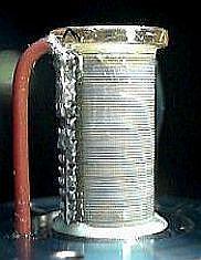
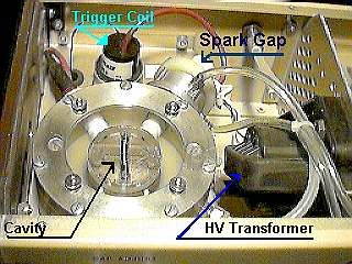
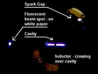
(These photos and description are from: Daniel Ames (dlames2@aol.com).)
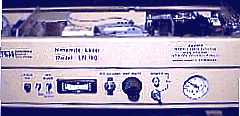
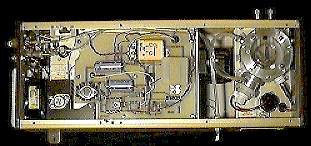
This is a Nitromite model LN100 nitrogen laser that operates at atmospheric pressure so it doesn't need a vacuum pump to operate. The laser is completely self contained except for the nitrogen gas. The manufacturer is PRA - Photo Chemical Research Associates, Inc. There is a very similar type N2 TEA at the Photon Technology International Model GL-3300 Nitrogen Laser Operation Manual Page.
The cavity is only 1.5" in length. This laser sure is a great example of the N2 UV lasing properties. When the spark gap's pressure is too low, the output power drops off substantially. With the spark gap's N2 pressure at atmospheric - it will not even lase. I have been using between 15 to 22 psi in the spark gap. These pressures seem to work well with this laser. With 15 psi, the pulse repetition is more uniform than at 22 psi. The cavity is not sealed so a flowing pressure of +1 or less psi helps keep the output stable.
Description and features:
The top cover has been removed for the photos.
There is much more information on N2 lasers in the Home-Built Nitrogen Laser chapters of Sam's Laser FAQ.