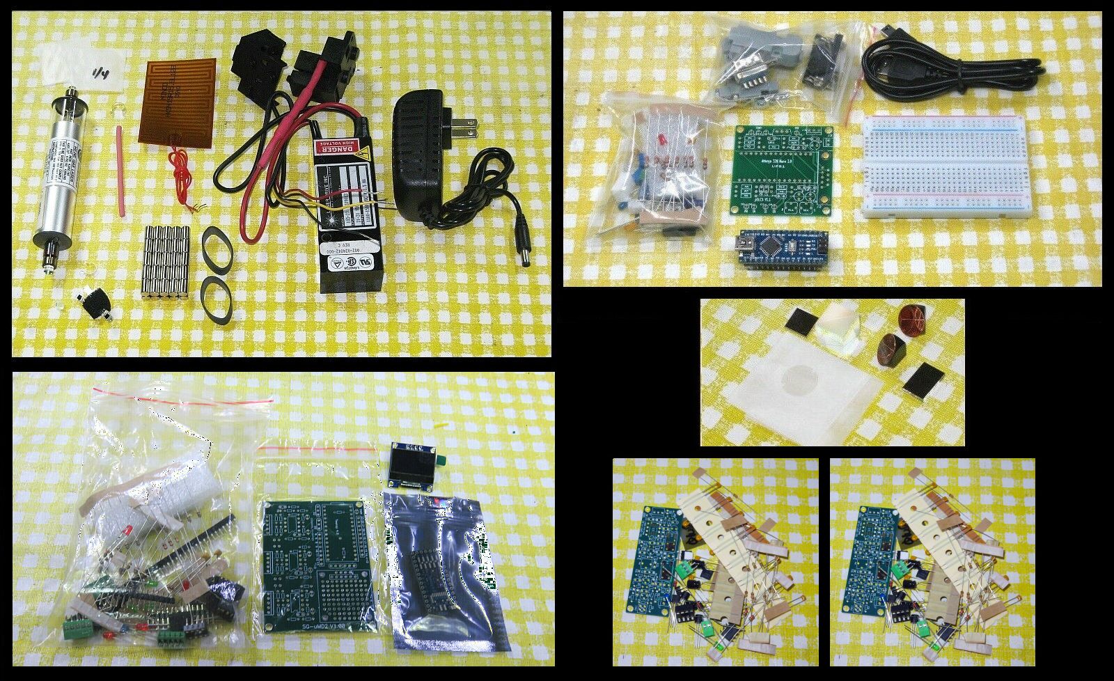
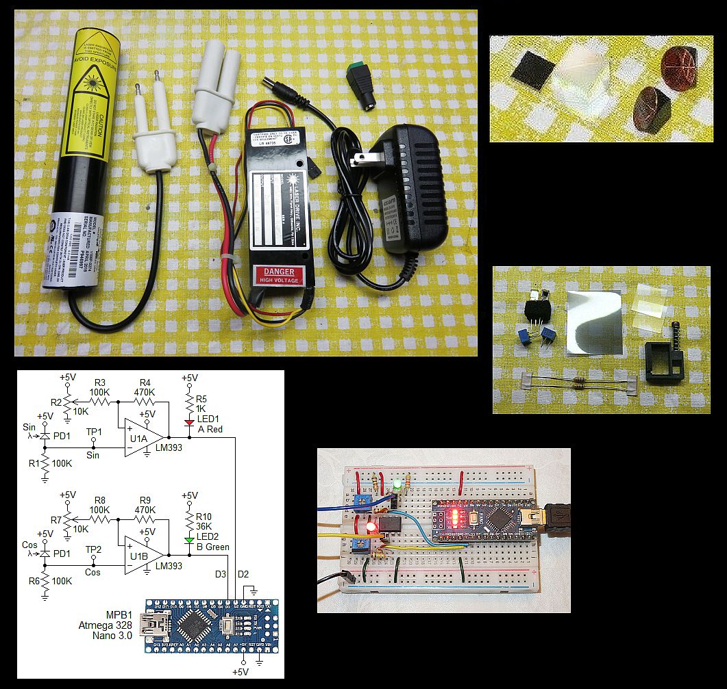
The typical parts are shown below:
Links:
- Stabilized Zeeman HeNe Laser Kit 1
with or without Arduino. The heterodyne kit use the Arduino version.
- Detectors for heterodyne known as "optical receivers" for these
are the SG-OR3, which provide functionality similar to that of the HP/Agilent
10780. SG-OR3 uses a relatively simple PCB so
construction is straightforward and Hathkit™-style assembly
instructions will be provided. See Optical Receivers
for Heterodyne Interferometers for more info. Unlike the commercial
optical receivers, these will run on 12 VDC, so no DC-DC boost converter
will be required. (The optical receivers for the "Hewlett Packard (HP)
Interferometer Measurement System-Hobbyist's Special 1,2,3" kits
will continue to be commercial parts.)
- Micro Measurement Display 2 (µMD2).
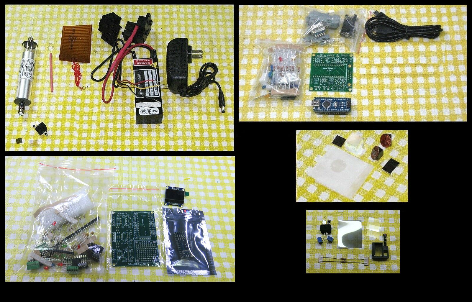
The typical parts are shown below:
Links:
- Stabilized HeNe Laser Kit 1 with
Arduino
- Construction Guidelines for Basic
Quadrature-Sin-Cos Decoder and Quad-A-B Interface Kits.
- Micro Measurement Display 2 (µMD2)
The detector in the kits for homodyne is quite primitive consisting of pair of biased photodiodes and with a Quarter WavePlate (QWP) to shift the phase of one of the signals by 90 degrees and the bandwidth is quite limited. But a better one could be constructed relatively easily.
This is similar to the homodyne system above but but with the µMD0 display.
Links:
- Stabilized HeNe Laser Kit 1 with
Arduino
Most of the tubes have a high divergence beam - around 8 mR. Therefore a collimating lens is included, probably in the bag with the optics. It has a focal lengh of 3-4 inches. Placing it close to the output bracket of the tube will result a beam that remains parallel enough for a short range interferometer (probably 1 or 2 feet). For longer distances, HP/Agilent beam expanders are available - ask. These result in a 3 or 4 mm beam which would remain fairly parallel over several feet.
- Construction Guidelines for Basic
Quadrature-Sin-Cos Decoder and Quad-A-B Interface Kits.
- Micro Measurement Display 0 (µMD0)
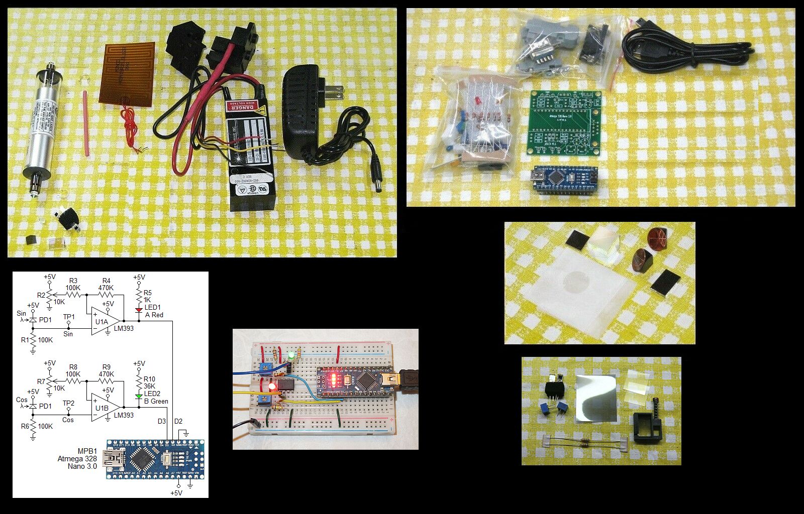
The typical parts are shown below:
Links:
- Instructions for Red HeNe Laser Kit 1
(Including Zeeman)
Set up the laser as it would be for stabilization EXCEPT that the polarization axes of the tube should be oriented at ±45 degrees, NOT 0/90 degrees. More on this below.
- Construction Guidelines for Basic
Quadrature-Sin-Cos Decoder and Quad-A-B Interface Kits.
- Micro Measurement Display 0 (µMD0)
The tubes provided in the minimal homodyne kits is well behaved (so it could be used in a stabilized laser as another project!). These have two axes of polarization at right angles to one-another whose orientation is fixed for the life of the tube. The amplitude of the power in each axis varies during mode sweep. A linear polarizer could be installed at 45 degrees to the polarization axes to convert the tube in effect to be very similar to a linearly polarized laser, but at the loss of more than one half the power. A better option is to orient the tube so that the polarization axes are at 45 degrees. The PBS cube in the interferometer will than see one half the power in both polarization axes and no power will be lost. However, interestingly, the Path Length Difference (PLD) for optimum performance will be at one tube cavity length, not at 0. For the ~6 inch tube and Linear Interferometer (LI), that is around 2.75 inches; for the Plane Mirror Interferometer (PMI) it is around 1.375 inches. If a PLD of 0 is used, the behavior is, well, very interesting. ;-)
In case you're curious, the reason there isn't an equivalent "Minimal Heterodyne Kit with Unstabilized Zeeman Laser" is that such a laser would generally not produce a split/beat frequency during part of mode sweep. For homodyne, as long as there is always at least one longitudinal mode present (with no gaps due to mode hops), the interferometer will work properly subject to the constraint that the path length difference is less than a few cm.
These laser produce a narrow beam (less thatn 1 mm in diameter), but because PLD needs to be small, the diameter at the detector should be similar for both the reference and measurement beams. However, if desired, beam expander can be added. Ask.
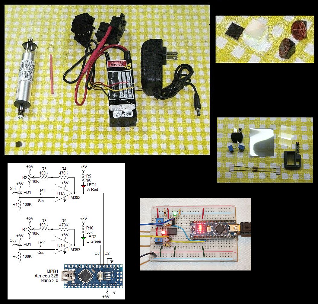
The typical parts are shown below:
Plug the high voltage "Alden" connectors of the laser head and power supply together securely if not already attached. The power supply will probably have a DC connector so it just needs to be plugged into the included wall adapter.
Orient the laser head so that the polarization axis is at 45 degrees. It will probably be marked but if not, is easily determined with a linear polrizer.
Links: