For contact info, please see the Sci.Electronics.Repair FAQ Email Links Page.
Copyright ©; 1997-2021
Reproduction of this document in whole or in part is permitted if both of the
following conditions are satisfied:
1. This notice is included in its entirety at the beginning.
We will not be responsible for damage to equipment, your ego, county wide
power outages, spontaneously generated mini (or larger) black holes, planetary
disruptions, or personal injury or worse that may result from the use of this
material.
These all use optical technology very similar to that of the compact disc
and CDROM. Thus, most problems with these cousins of the CD will be similar.
See the document: "Notes on the Troubleshooting and Repair of Compact Disc
Players and CDROM Drives" for an introduction to the basic technology, general
maintenance procedures, and diagnosis of most common problems. This document
addresses those aspects of the technology and repair that are unique to each
of these other formats. Problems with Sony PlayStation PSX (and similar)
CDROM-like game machines are covered there as well.
Once CD (and DVD) rewritable technology becomes more popular (and lower in
price), these will be added. I currenty have little information on this
equipment.
Contributions are always welcome as you will note that there really isn't that
much specific information at the present time on anything other than LaserDisk
players and even this is sparse. I don't expect that much interest in or
offers of CD-R, WORM, or MO repair information. However, MiniDisc has some
sort of a following and we are destined to be inundated with DVD problems in
the near future as they replace CDs as the equipment of choice. I am still
waiting to see the inside of a DVD player - working or otherwise :-).
This isn't that much of a problem with LaserDisk players since the laser power
is likely (but not guaranteed!) to be similar to that of a CD player where
relatively minimal precautions are adequate.
However, for the technologies which can record or write on an optical disk,
the laser power may be much higher and instant irreversible damage to vision
is quite possible. Furthermore, these are almost always IR (infra-red) lasers
which are for all intents and purposes, invisible. Proper precautions are
essential and laser-blocking goggles are definitely recommended whenever
the unit is powered without a laser shield in place. Once you damage both of
your original equipment eyesballs, you don't receive any replacements (even if
they are still under warranty - read the fine print of your contract)!
General safety precautions:
While there are fewer potential dangers involved in servicing an LD player or
MO drive compared to a TV, monitor, or microwave oven, precautions are still
required when working with the cover removed. These relate to electrical
connections to the AC line, getting caught in the mechanisms, and exposure to
the laser beam:
Some equipment such as LaserDisc players may use switching power supplies
with their own set of problems. Internal drives may include their own DC-DC
converters as well (which are not particularly dangerous but can be easily
damaged through the careless slip of a probe). In these case, see the
document: "Notes on the Troubleshooting and Repair of Switchmode Power
Supplies" for more information.
Where an older LaserDisc player uses a Helium-Neon (HeNe) laser, there will
be a high voltage power supply for the HeNe laser tube. While some are
not powerful enough to kill you, a reflex action from touching the
wrong terminal can result in collateral damage like ripped flesh from sharp
sheet metal parts. These terminals are usually clearly marked and insulated
but make a note of their location to be safe and add several layers of
plastic electrical tape if they are exposed.
But some older ones like the original Magnavox LD player may be potentially
lethal. This had a linear power supply operating off a winding on the main
power transformer with 60 mA possibly being available. That model also has
a large power supply PCB with limited protection against coming in contact
with exposed circuitry. Later ones had much more limited current capability.
(Some of of this from a former Philips/Magnavox engineer.) So take care with
all of these relics.
In addition, ground connections may depend on all the modules being
installed and secured:
"I had the opportunity to take apart an old Panasonic LD player in
college and learned the hard way how vital the ground strap from the
case of the HV laser power supply to the laser tube assembly is when
both are removed from the metal LD chassis and operated on their own.
Even with all the proper connections, I had one hand on the metal
shroud for the tube when I switched on the power with the other
hand.> I was knocked out and came to a few minutes later. Luckily I
had switched off the circuit as I got hit hard."
MANY OF THE HIGHER POWER LASERS ARE LIKELY TO BE IR AND INVISIBLE! You won't
be able to see a bright beam you can avoid! The lasers in all CD drives
are infra red, near IR - around 780 nm - border of visible range but for all
intents and purposes invisible. This is also true of most older optical
drives. While the laser is supposed to be set to
low power for playing or reading POWER CIRCUITS CAN FAIL! Don't take any
chances. At most, you will see a tiny red dot in the lens as shown in
Appearance of IR (780 nm) Laser in CD Pickup.
(Original photos courtesy of Gag Helfront (ie.dunster@ukonline.co.u).)
DVD drives use a laser diode with a wavelength around 650 nm, which is red
(similar to many red laser pointers).
With a visible beam, it is easier to avoid exposure and LD and DVD players
use low power lasers anyhow. Reflections at these power levels are not
strong enough to be a serious hazard.
As a comparison, these will likely be similar in power level (5 mW) to the
brightest laser pointers currently on the market and are a definite risk to
vision at close range. Still, being visible, it is easy to avoid direct
exposure. But DVD recorders and writers
use much higher power visible lasers - some over 100 mW as noted above.
However, for an IR laser producing an invisible beam, there is no way to
reliably avoid the beam visually. With the optics intact (no damage to the
pickup and none of the covers on the pickup removed) and a disk in place on
the spindle or the lens covered with black tape (no holes!), it should be
safe to work at a reasonable distance. Don't put one of your eyeballs up to
the optical block - there could always be a light leak! Proper IR blocking
goggles would definitely be a good idea where exposure to these higher power
lasers is possible.
CAUTION: There is usually a very low intensity (in appearance) emission
from an IR laser which appears deep red. It will be visible as a spot the
size of the period at the end of this sentence when the lens is viewed from
an oblique angle. This is just your eye's response to the near IR energy of
the main beam. (Some people apparently cannot see this at all.) Do not be
mislead into thinking that the laser is weak as a result of how dim this is.
The main beam is up to 10,000 times more intense than it appears! It's
power output is generally around 1 mW - comparable to a laser pointer. Take
care. However, the red dot is an indication that the laser is being powered
and probably functional, though it is no guarantee of the later. You really
need a laser power meter or at least an IR detector to confirm the existence
of an IR laser beam.
Blu-ray and other higher density devices operate close to 400 nm, which is
borderline near-UV. It, too, is nearly invisible, but a very deep purple
rather than a very deep red. Similar precautions to near-IR lasers should
apply.
The earliest (Nov 09, 1996) archive seems to be the most complete.
Also check out:
The following site has a variety of information on CD and DVD technology:
A site with CD-R specific information including some repair tips is:
An extensive amount of information on other optical disc/k technologies with
many useful links can be found at:
In terms of performance, video quality from the LaserDisc medium can be far
superior to even SVHS and SuperBeta, and competitive with DVD when viewed on
a correspondingly high quality TV or monitor. Like a CD and unlike tape,
access to any scene or even frame is quite fast. This is definitely a
significant advantage for the casual viewer but was the
enabling technology for interactive instruction and games. With up to
54,000 or more individually accessible frames on a side, this was a potentially
very powerful way to present information as combinations of
stills and moving segments and permit context dependent control of access
or video action.
However, note that except for some control codes representing a very small
number of bits that identify things like format and time/chapter/frame on the
disc, LaserDisc is a totally analog format as far as the electronics are
concerned (though the information on the disc surface is in pits and lands as
with CDs and DVDs). The video and audio channels are assigned separate
frequency bands and are demodulated with analog circuitry. There is
no digital error checking, though some players include a 1 line video memory
to help conceal dropouts by replacing missing video with the line above.
And, some newer LD players may have a digital frame store to allow for
noise-free implementation of functions like freeze frame, slow motion,
and so forth, on CLV discs (see below).
There are two basic LD formats: Constant Angular Velocity (CAV) and Constant
Linear Velocity (CLV). For CAV, the disc rotates at a constant 1,800 rpm
(NTSC) or 1,500 rpm (PAL). All special effects like still/freeze frame and
single frame forward or reverse, slow motion, and individual frame
addressing are available in CAV mode. Some players can search to a
specific frame number in only a few seconds. However, the maximum
length of program material for CAV is only about 1/2 hour per side as
there is less efficient use of space as the pickup moves toward the
outside of the disc. For CLV, the total program time approximately
doubles to 1 hour per side. The rotation rate of the disc slows down
(like a CD or DVD) as the pickup moves toward the outer edge. However,
without a sophisticated digital frame store, most special effects are
disabled (or don't work at all well). Fast scan is functional but
except near the beginning of the disc where the rotation rate is
similar to that of CAV and the video on successive tracks likes up,
the result is a broken up picture with loss of color. There may
be no sound with special effects for either mode.
Most feature length movies were released in CLV to achieve the maximum
time on a each disc. However, if there was enough space without increasing
the number of discs or sides, some potions might be in CAV to have the
special effects.
There were a variety of audio formats used, the most common being stereo
with quality approaching that of CDs.
The video aspect ratio was something that seemed to be played with quite a bit
with later releases tending toward various letter-box and wide-screen formats.
Most will play fine on any standard TV or monitor that supports the "normal"
4:3 aspect ratio, but the top and bottom will be black. And when this gets
to be extreme like 2.35:1, there is a loss of quality simply because so
much of the screen (and resolution) is being wasted. However, there were also
a relatively small number of "Squeeze" format LDs. These expected a true 16:9
aspect ratio TV and will look squashed horizontally on a normal 4:3 aspect
ratio set unless it has a corresponding mode.
High-end video enthusiasts used to swear by LaserDisc technology but this
medium never caught on due to the relatively high cost of both the equipment
and the software (movies), limited rental availability, and because it is a
play-only media. In addition, the capacity (NTSC) of a single LaserDisc is
around 1 hour total (both sides) for CAV or 2 hours (both sides) for CLV
requiring more frequent disc changes than for VHS/Beta or now DVD even if
the player had dual laser pickups or a mechanism for moving a single pickup
to read both sides.
Nowadays, LaserDisc is considered history, replaced by the DVD which is
smaller, cheaper, with additional features and flexibility, and with
potentially superior picture quality. However, there is still an active
market in used LaserDiscs and players, and for many purposes, the LaserDisc -
especially given the declining cost since so many are dumping it - is an
attractive alternative to putting together a high quality video collection
inexpensively. Prices on eBay for individual LaserDiscs currently range
for under $1 to perhaps $30 (depending on the title and condition). The
winning bid price for perfectly usable - and sometimes full featured - players
may be less than the shipping cost. At any given time, there are typically
over 100 LD players for sale on eBay ranging from working vintage machines
from the early '80s or before, to the state-of-the-art when production was
discontinued.
The LD disc is a sandwich of two 1.2 mm thick 12" platters glued together
with the information layers on the inside. In fact, the thickness, track
spacing, and pit and land sizes, are very similar to that of CDs and probably
provided the basis for the ultimate CD specification. But there were never
any double-sided CDs. Most DVDs are a sandwich of a 0.6 mm thick platter
with the information content, and a 0.6 mm blank blank platter to make the
DVD 1.2 mm thick. The DVD specification also supports two sided DVDs, which
are a sandwich like LDs but only 1.2 mm thick, as well as two layer DVDs
have information recorded at two depths but are read from the same side.
But there were never any two sided CDs.
The basic eletro-optical mechanism is similar to that with a CD, DVD, HD DVD,
or Blu-ray disc/k including the techniques used for beam generation, focusing,
and tracking. However:
For general information on LaserDisc, see:
Bob Niland's
LaserDisc FAQs. These include the format, features, problems, and more.
Note that the LaserDisc format is totally and absolutely different than
that of the RCA Selectavision CED (Capacitance Electronic Disc).
Even though the discs are the same size, they are totally incompatible and
will likely cause damage to both the disc and player if any attempt is made
to even load one type into the other type of machine. This
last gasp of the USA consumer electronics industry reportedly costing
RCA several hundred million dollars to develop was based on such archaic
technology as to be laughable, at least in hind-sight when lasers were
still expensive and optical disc technology was in its infancy. CED used
a stylus like old fashioned records. The stylus was a capacitance sensor that
mechanically tracked a physical groove (almost 10,000 per inch) in a pressed
vinyl disc rotating at 450 rpm (compared to 33-1/3 rpm for the most common
long playing record). Wear, damage, dust, dirt, and other contamination was a
major concern so the disc was enclosed in a caddy and cleaning was not really
possible. It's a minor miracle these worked at all! However, there are still
collectors out there who keep the spirit of the format alive.
For more information than you could possibly ever want, see
Capacitance Electronic
Discs.
(From: Mark Zenier (mzenier@netcom.com).)
The original version is covered in The "Television Engineering Handbook"
edited by Benson from McGraw-Hill, 1986. Don't know about the newer version
with digital sound. (Or what the newer edition of the book covers, either).
It's an analog FM system at 8 MHz that records the composite signal, with two
FM audio carriers at 2.3 and 2.8 MHz.
It is NOT related to LaserDisc technology and does not use an optical pickup.
If you found one of these, you have a classic dinosaur! The CED system was
something RCA spent $200-300 million to develop about the same time that
LaserDisc technology was being perfected. Guess which won!
And, this was shortly after the same company spent a similar vast amount of
money on another consumer electronics dud. It was also named Selectavision if
I recall correctly and used optical scanning of 4 mm (??) movie film.
CED uses a capacitive contact sensor 'sled' running in a grooved disc.
The pickup actually rides on the disc like the stylus on a phonograph record.
The sensor detects minute changes in the capacitance between the tip of the
pickup and the metallized surface of the disc embossed with millions of tiny
bumps and valleys.
This really isn't that bad - the system DID work but suffered from some of the
same problems as records - wear, critical tracking requirements, etc.
If you are trying to resurrect a CED player, you better have the discs you
want because they will not be available at your neighborhood video store!
Since it is more than 15 years old, there can be any number of problems with
the equipment just from age and non-use. These are likely to be both
mechanical (gummed up grease, dirt), and electronic (dried up electrolytic
capacitors in the power supply, bad connections, etc.).
However, chances are good that it wasn't actually broken to begin with since
consumers likely gave up on this technology before it actually failed - there
just wasn't enough movies/programming available.
Start by checking the obvious, reseating all connectors, testing power supply
voltages and for ripple, etc.
It certainly would be cool to get working.
MDs may be pressed like CDs with the information encoded in pits and lands.
This is the way prerecorded play-only MiniDiscs are made.
For recording, the MiniDisc technology uses a higher power laser beam (upped
to 5 mW at the disc surface) to heat a magneto-optically active coating to
above its cure point (where magnetization is lost). A writing coil in close
proximity to the back of the Minidisc is used to switch the magnetic field
polarity (N or S) of the coating as it cools. Thus, the laser beam may be
thought of as 'softening up' the magnetic material but the actual writing is
by the coil. This is not the same way most other writable magneto optical
drives are implemented. See the sections: "WORM drives" and "Magneto optical
drives" for more details on these other media.
For playback of this magneto-optical (MO) recording, the pickup uses what is
known as the 'magneto-optic Kerr effect'. When a polarized laser beam is
reflected from the disc coating, its polarization orientation is rotated
slightly depending on the magnetic field polarity (N or S). This rotation
is small (about 1%) but enough to permit detection. However, since it is
so small, it isn't surprising that there can be problems with the optics and
front-end electronics for MO readback.
Thus, the MiniDisc pickup and front-end operates in three modes: spatial (pits
and lands) read, MO read, and MO write.
The basic mechanism and optical pickup is similar to that of a CD including
the techniques used for beam generation, focusing, and tracking. However:
The basic components are very similar and thus cost of manufacture will be
similar. So, why produce old fashioned equipment?
The DVD permits storage of up to 4.5 GB per information layer with up to 2 of
these on each side (one under the other) for a total of 18 GB if fully
implemented. This means (per layer):
From a marketing perspective, it is essential for DVD equipment to support
the CD format. However, since DVDs and CDs differ in terms of feature size,
track spacing, thickness, and so forth, it would not be very effective to
simply shine the DVD pickup at a CD! Either of two approaches may be taken:
Some people seem to think blue lasers are used for DVDs. One reason may be
that manufacturers are putting blue illumination on the front panels and maybe
even inside the disc compartment of DVD players - solely for marketing reasons.
However, blue or UV lasers (e.g., argon or krypton ion) may be used to write
the glass master for DVD (as well as CDs) where the shorter wavelength results
in crisper more accurate rendition of the pits and lands of the information
layer. Of course, these machines cost $250,000.
Converting to a shorter wavelength laser for readout won't help anything
except the manufacturer's bottom line assuming they could charge much more
for the hype than the additional cost of the laser. Currently, the only
viable option is the Nichia 400 nm violet laser diode which go for about $2K
each! To take advantage of a shorter wavelength laser, the entire standard
would need to be revamped. I have already named the new standard: the
"Digital Ultra Disc" or DUD. :) Once those violet lasers (or alternatives)
come down in price, there is little doubt that the World will be treated to
yet another advance in technology whether anyone wants it or not.
Here is my take. My track record isn't great on predicting the future as my
crystal ball has been broken for a long time, so don't buy or sell shares
in any company based on these comments!
DVD will do very well for data storage since due to its much higher capacity
compared to CDROMs (5 to 20 GB versus .64 GB), it will serve an important
purpose in the increasingly interactive applications and games to come.
Full size DVD will be overkill for many audio applications. At the normal CD
audio sampling rate of 44.1 K/second, the smaller DVD format will hold over 8
hours of music. Whether people will be willing to pay the expected price for
a DVD with several hours of music is questionable. There certainly will be
many good reasons to do this - full concerts or operas on a single disc, for
example. I would expect the average total length of normal musical DVDs to
increase beyond what is typical of CDs as well.
However, mini-DVDs are possible. A 3-1/2" format would hold about 1/3 as
much as a full size DVD or over 2 hours of music. This or an even smaller
format would be ideal for discman applications.
What about multilinqual sound tracks? Sure, this capability may save money
by requiring pressing of only one disc to support multiple markets. But,
few people will have a need to pay for this.
There are no doubt all sorts of applications that have not been identified
yet for which the DVD is ideal. However, the hopes of the industry are pegged
to DVD's success for video - in part, to replace the consumer (VHS) VCR.
Unfortunately, It is here where I believe DVD has its greatest weaknesses.
Many of the specifications have been developed tailored to today's video
standards, not HDTV. The DVD is supposed to be superior to both VHS VCR and
laserdisc formats. However, this is in comparison to standards (NTSC and PAL)
that are close to celebrating their 50th birthday. Even the quality advantages
are questionable as so much depends on the MPEG-2 encoding used to compress the
vast amount of video information onto the DVD.
Video tape and laserdiscs do not care what is recorded on them - they are
equally good or equally poor for static scenes as well as explosive action
shots. This is not true of DVDs. Complex images and rapid scene chances
require more bits to minimize artifacts. And, the types of artifacts that
are introduced are not those one expects from poor reception or bad tapes.
It will take a great deal of effort on the part of the companies who will
be converting original movies and other source material to the DVD to do
justice to the format. It may simply be impossible for certain action
sequences. The result may be 'pixelation' or momentary blockiness, erratic
motion, momentary freezes, and so forth - not just slight fuzziness or snow.
It is not known how the general viewer will accept these. Developers of source
material will not be free to put in whatever they desire. The medium may
break down when presented with too much fast complex action or rapid scene
changes.
The situation gets even murkier for HDTV where the required amounts of data
and data transfer rates increase dramatically. Depending on HDTV format,
this could be anywhere from 2:1 or 8:1 - or more. If the DVD is marginal now,
what does this say for HDTV?
Initially, DVD will not have record capability. Thus, there will be no
compelling reason to switch over and throw out your VCR especially if the
quality isn't dramatically better. The majority of consumers don't care
that much about picture quality anyhow. Beta, S-VHS, and laserdisc, all have
substantially better picture quality than normal VHS and NTSC broadcasts.
It has not mattered due to various usability issues and marketing stupidity.
The critical mass was never reached with respect to availability of source
or rental tapes or discs. Thus, these have been relegated to niche markets
and niche markets don't drive the industry.
Will DVDs turn into yet another Edsel, Selectavision, or Betamax? Only time
will tell but the industry must make a deliberate effort to assure the quality
of the initial releases or else DVD's future as a video media will be sealed
before it gets off the ground even if the technology there.
The earliest were called WORM (Write Once Read Many) drives. Writing
resulted in an irreversible change in an information layer. Thus, data could
be written but not erased and rewritten (though just erasing a block might be
possible). Heating with the writing laser beam resulted in damage (ablating)
of a coating. Reading is similar to that used for CDs and other optical
technologies.
Typical capacity was 650 MB per side. Disks could be one sided or two sided.
This is somewhat similar to the technology used in CD-R drives though many
variations have been developed which vary mostly in the details.
Unlike CDs, MDs, and LDs, these optical discs are formatted more like hard
drives or diskettes with circular (not spiral) tracks and fixed sectors - some
of which are visible to the naked eye since they are physically etched on the
disk itself.
The laser power for WORM drives is typically higher than for read-only drives
when in writing mode - likely in the 10s of mW range. 30 mW is one number I
have heard. Modern drives all use IR emitting laser diodes.
The basic mechanism and optical pickup is similar to that of a CD including the
techniques used for beam generation, focusing, and tracking. However:
The media is usually enclosed in a cartridge for protection with a door that
opens automatically when inserted into the drive. Capacity is typically
650 MB per side for a 5-1/4" disk.
Although CD-R started out being quite expensive (greater than $10,000 for a
recorder), it really was designed as an inexpensive technology and to have
total compatibility for reading with CDs and CDROMs. Current prices for
multispin (2X, 4X) CD-R recorders are under $500 and dropping. The capacity
of a CD-R is the same as a CD - about 650 MB.
Like the WORM drive, a higher power laser ablates a coating inside the CD-R
media. With most, this is a blue-green polymer dye backed by a gold coating.
Otherwise, construction of the CD and CD-R media are similar.
However, since the pits and lands are not as precisely formed as those of a
pressed CD whose master was made on a $250,000 laser cutting lath, some CD
players or CDROM drives may have tracking or other problems with CD-Rs.
CD-R recorders and high performance CDROM drives are very similar except:
Modern LD players use the same 780 nm laser diodes as CD players. Really
old players used Helium-Neon (HeNe) gas lasers resulting in a visible beam
at 632.8 nm (orange-red). CAUTION: these use a high voltage power supply.
Contact with this probably won't hurt you but will not be pleasant. The
high voltage terminals are probably well insulated but it is a good idea to
locate them and double check.
Since most newer LD players also play CDs and some even play DVDs) there will
be optical sensors - LED-photodiode pairs aimed at the disc from one or more
locations, probably beneath the drawer assembly. (Most also play multiple
size LDs as well which also use similar sensing.) If you have the top off
for servicing, room lighting may confuse these sensors resulting in all sorts
of strange behavior such as attempting to play a CD using the LD spindle!
Cover the entire unit with a piece of cardboard or just the holes in the
drawer with matt black paper to eliminate the possibility of both electronic
and human confusion!
LD players will generally have one additional servo system compared to CD
players - tilt. This adjusts the angle of the pickup with respect to the
disc to minimize interference between adjacent tracks. This would result in
degradation of the analog video signal. The tilt servo is usually pretty
simple using an IR LED emitter and a pair of IR photodiodes detecting the
reflection from the laserdisc. If after manually rotating the tilt motor
away from the balanced position, the tilt readjusts itself, there is a good
chance this it is operating correctly. There is probably a tilt balance
adjustment as well but don't touch it unless you have the service manual
if possible.
Spindle motors in LD players are of much higher quality than typical CD
players since the spindle must spin continuously at thousands of rpm with
the greater mass of the LD as well. Other motors may be similar to those
in CD players. Some LD players have two spindles that are selected and
moved into position depending on the type of disk being played.
Due to the mass of LDs, the clamper is even more critical to proper behavior
than for CDs. Any slippage and LDs may fail to be recognized.
There may still be rubber belts that degrade :-).
Naturally, a video monitor makes an excellent diagnostic tool once it is
possible to obtain some output from the LD player. A service manual is
almost a must for serious troubleshooting.
I recently acquired a Pioneer VP-1000 in working condition. Considering
its age of roughly 25 years, this is rather remarkable. Except for a
sometimes quirky startup, it operates flawlessly. They used to build
these things to last! :)
(The startup problem is that it doesn't like to reset the pickup quite back
to the home location - a gentle push reseats it. This doesn't appear to be
a lubrication or similar issue as as the pickup moves freely on its rail and
everything is clean with no grease ever being used. But the pickup is buried
under circuit boards so getting to it may not be worth the effort.)
(Update, in 2016, I sold the VP-1000 still in working condition. In fact,
based on my experience, the majority of Pioneer HeNe laser-based LD players
are still in operating condition 30 to 35 years after their manufacture.)
A diagram of an even earlier LaserDisc pickup prototype is shown in
Optical Path of Early HeNe Laser-Based LaserDisc
Prototype. The Wollaston prism is a rather unusual optic which
probably never made its way into any commercial unit due to the small
separation the polarized beams and its extremely high cost. The Pioneer
LaserDisc player, above, used a more conventional polarizing beamsplitter
cube (still costly but much less so than the Wollaston), and more recent
CD and DVD pickups typically use an even cheaper dielectric coated plate
beamsplitter. But otherwise, the designs are very similar. However,
some of the newest cost-reduced pickups do away with the polarizing
components entirely by offsetting the outgoing and return beams.
This probably reduces the performance slightly, but who can argue
with the bean counters? :)
For more information on optical pickup principles of operation and examples
of newer technology, see the document: Compact Disc
Players and CDROM Drives.
The following is a further confirmation that optical alignment should not be
needed under normal conditions:
(From: Dave A. Wreski (dawreski@nic.com).)
I have been servicing these since they came out. The *only* time I had
to do any optical alignments is when some fool decided to mess with the
alignments. They do not misalign themselves. In the past the only adjustment
we had to do (on Pioneer Laserdisc players) is the 1/4 wave plate which
can be done with a scope. All other alignments must be done with a Laser
power meter and a polarization adjustment jig from Pioneer. Many dollars!
If the optics are clean and haven't been maladjusted, your unit is supposed
to work. If not, look elsewhere in the electrical alignments or motor problems.
(From: Sam.)
I acquired a VP-1000 that indeed did have obviously misaligned optics. (This
is a second VP-1000, not the working one described above.) The VP-1000
is a HeNe laser-based unit and the output mirror of the laser tube itself
was misaligned, reducing power by 40 percent. The beam out of the objective
lens was also clearly asymmetric, indicating misalignment of at least one
of the bounce mirrors. This LD player would not even focus, but an
electronics problem was likely also present as it did attempt to focus, and
was definitely seeing a return beam as the behavior changed if a CD or
mirror was placed above the objective lens while it was attempting to focus.
But we shall never know, as it's organs have since been harvested. :( :)
Note that since the LD standard was designed around the 633 nm wavelength
of the HeNe laser, there is some merit to the claim that these gas tube
laser-based LD players had better performance than at least early diode
laser-based units since the latter were at 780 nm like CD players since
they were the first to become economical in the mid-1980s. I do not
know if later LD players ever went to red laser diodes as their price
came down.
I (Sam) do have original tubes in healthy condition that were from Pioneer
LaserDisc players. I believe these will fit any Pioneer HeNe laser-based
unit. I do not know what the other manufacturers use but they are either
identical or should be similar enough to be substituted. See my listings
on eBay under user ID: siliconsam.
However, it should also be possible to substitute a surplus HeNe tube and/or
HeNe laser power supply. The tube will have to be of a similar power output
(usually around 0.5 to 1 mW) and physical size. It also needs to produce a
linearly polarized beam (which eliminates a lot of the common barcode scanner
tubes as replacements). If the beam diameter and divergence are similar, it
may be possible to get by without any change to the optics as long as the tube
is carefully mounted with its output in the same position and orientation as
the original. However, some minor optical alignment will likely be required.
For this, it is best to have a service manual but even that may not help if
special factory jigs are required. However, see the section:
Pioneer HeNe laser-based LD player HeNe laser
tube replacement and alignment guide. It
is suitable for all Pioneer HeNe laser-based LD players and probably
most others as well. This may in fact be better since it doesn't
require any special costly and unobtainable jigs. But it
does assume that the alignment is fairly close to start.
HeNe laser tubes with power supplies can be had for as little as $25 from
various mail order sources but you need to confirm compatibility. It may be
possible to compensate for a different beam diameter and/or divergence by
adjusting the external optics. However, you can't easily get a non-polarized
tube to produce a polarized beam. (It can be done with powerful magnets but
this is probably not a viable option inside a cramped LaserDisc player.)
If a suitable HeNe laser replacement is unavailable, too expensive, or just
too mundane, it may be possible to use a diode laser - even a laser pointer -
in its place. The beam characteristics would need to be similar with respect
to divergence and polarization. A unit with adjustable focus will probably
be best to match up divergence. Since, all diode lasers are polarized, that
at least, shouldn't be an issue. Apparently, some people have successfully
done such a transplant without major problems. But note that some of the
optical components are moderately sensitive to wavelength. So, a 650 nm laser
diode may be far enough away to cause problems. The most difficulty may arise
from devising a suitable mounting arrangement and providing the stable low
voltage power needed for the diode laser or pointer. I'd still recommend
staying with an HeNe laser if possible but at least, there is an alternative
that will keep your prized 1979 LaserDisc player going strong. :)
And, if that's not enough, alignment can be a real pain, whether it simply
after replacing a HeNe laser tube or installing a diode laser. The assembly
and alignment procedure in a Pioneer LaserDisc service manual is several pages
long and relies on multiple special jigs, none of which of course are still
available. But the alignment procedure linked above may be good enough
for a tube swap.
(From: dwb@rell.com).
I had a problem with my Kenwood machine not locking the disc in place
correctly. The disc loading drive belt was slipping, though I couldn't
hear it. The replacement was a NEW mechanism that regeared the assembly
for slower feed but much more clamping force.
And the design of the optical pickup (slider) and entire machine
is quite different than that of the Pioneer LD players of similar vintage
discussed below. However, it's not clear that these players ever worked
properly even when new. They were not reilable and may have had design
problems. Unlike early Pioneer HeNe laser-based LD players which are plentiful
even in 2007, with many being fully functional, working samples of the
VCH-8000 are rare to non-existent. And it appears as though even Magnavox
gave up on the design because their second generation LD players are made
by Pioneer and are actually LD-1100s inside! :)
The HeNe laser is in an enclosed laser head made by Philips. The slider
optical design is similar to the one in Optical Path
of Early HeNe Laser-Based LaserDisc Prototype. Note the unusual
double Wallaston beamsplitter prism. Possibly this predates the wide
use of the more normal polarizing beamsplitter cubes since it is both
more expensive and more difficult to use with the small deviation of
the two beams.
The low voltage power supply and HeNe laser power supply are on a single
large Printed Circuit Board (PCB), with a separate start module. Most of the
signal and motor driver electronics are on around 20 tiny plug-in PCBs,
each of which is individually shielded. The power supply PCB and backpanel
for the tiny PCBs swing out from the main chassis for servicing, so that
at least makes sense.
To get a true feel for the construction, it's best to look at photos.
See Magnavox VCH-8000-CH01 LaserDisc Player Gallery for a series
of photos provided by David Miyares. The collection from which this was
derived may be found at
Picasa
Magnavox First Production LaserDisc Player.
The VCH-8000-CH01 I have is in generally good physical condition except for
a rotted slider drive belt. I replaced it with a flat belt made by slicing
off a piece of a bicycle inner tube. :) The laser seems to work since it
definitely does something different depending on whether a valid LD is
loaded. It spins up and seems to be happy (even before finding the bad
belt) only with an LD in place. Otherwise, it just clicks which is probably
focus search and the lens is hitting the stops. And the sound output
is just noise.
At first, I didn't even bother connecting it to a TV expecting nothing to
show up. But knowing that the video signal should make the best diagnostic,
I first tried what I thought was baseband video into a portable DVD player
used as a monitor, but this produced nothing at all. The outputs are
not well labeled on the VCH-8000-CH01! Then assuming it was actually RF,
I connected my 6 inch color TV, used for testing LD players. There was
still nothing useful to report. But after fiddling with the "Chan 3/4"
switch and random front panel buttons, it now sometimes
produces a distorted but marginally recognizable B/W picture with a CAV
LD. (I later determined that the "Aux Video" is actually the baseband
signal, but this appeared dead at first.) Getting any recongnizable
video at least means the optics and front-end signal circuitry
are working, but tracking and/or timebase correction may be faulty.
Only when there is a stretch of identical frames (as
with a title or the Laser Vision logo) is the picture close to normal,
though there is still no color. With a CLV LD, it's still possible to get
video, but the picture is much more jumbled and unstable.
The only front panel LD motion controls that work beyond
turning on their mode LEDs are "Forward Search" and "Reverse Search",
and only in a more or less sort of way -
Forward may be moving normally, but Reverse goes only a few dozen or
a few hundred frames before getting stuck. This may mean the slider
motor or its driver is faulty.
However, there is audio noise only when the machine thinks it is
in Play mode, and just a
hint that the noise may actually be an indication of normal audio, if
the other issues could be resolved.
And, joy of joys, the "Index" button will turn on the chapter or frame number
display, which is relatively stable. Although the numbers do jump around
somewhat even when the picture is not changing, this means
the readout of the LD's digital data is working.
If left alone, the location on the LD (based on frame number)
sometimes wants to drift backwards, until it ends up eventually
at the inner stop (and then the LD takes off like a jet turbine, having
lost the video sync signal).
So far what works:
What doesn't work:
Next, I wanted to determine if the tracking and tangential (timebase)
deflectors were working properly. These are under a plastic cover
accessible from underneath. It requires pulling off a few connectors,
1 screw for the cover, 1 ground connection, and 2 screws
to remove the deflector assembly itself. Compared to the deflectors
in the Pioneer LD players, these are rather stiff, which could be
part of the problem. Gently working them back and forth a bit seemed
to loosen them up a bit. I tested with 3 VDC to make sure they
responded. The mounting is somewhat keyed, so I don't think optical
alignment should have changed much upon replacement.
Behavior was similar except that every now and then, there would be a
bit of color showing up. I then decided to try some careful adjustment
of the tracking servo. The little modules are labeled and one had the
word "Radial" in it, with 2 pots. Running this thing while being able
to access the modules requires lifting it about 2 inches off the table.
A set of 4 threaded metal spacers works well enough, though maneuvering
it into position isn't fun.
Turning one of the pots on the Radial module fully clockwise seemed to
help some with color showing up almost constantly and much less jitter.
However, the other pot had no effect. So, I rather suspect some problem
with that module.
Unfortunately, something else must have been degrading as it was becoming
more and more difficult to achieve focus lock when starting an LD, though
once lock was successful, it would almost always remain locked indefinitely.
But eventually, it became essentially impossible to achieve focus lock,
and the machine seemed to become more angry and stared attacking the LDs
with the objective lens, resulting in scoring of the LD surface.
So, that's where things stand.
My hypothesis at this point is that the main problem is in that tracking
and tangential scanner assembly and it needs to be realigned (at the very
least). This could possibly be done simply by loading an LD and turning
ONLY the laser on with nothing else powered. The LD player could then be
placed face-down on a cushioned surface. Then adjust the angle of both
mirrors so the beam returns precisely to the photodiode array - somehow.
Hopefully, the slider being upside-down would not affect alignment enough
to matter - hopefully! :) I couldn't imagine trying to do this with the
player in the normal upright position!
A possibly simpler alternative to physical alignment may be to figure out
how to introduce an offset electrically into both axes of the scanner to
force each mirror to the proper orientation. If the error is small,
this may be all it takes to get it working. But there
don't appear to be adjustments pots for at least one of these, as hard as
this may be to believe. So a pot or pots may need to be added.
However, if the mirror suspension is actually rotted and no longer as
springy as it needs to be rather than just slightly shifted due to age and
neglect, none of this will really help beyond possibly confirming that
the scanner is to blame for the demise of these players.
I did acquire a second sample of the VCH-8000-CH01 with a similar rotted
belt, which was just sitting on the bottom cover when it was
removed, despite the seller claiming that the machine worked perfectly! :( :)
I never could get that one to do anything productive beyond spinning the LD
(after replacing the belt) though it may perhaps serve as an organ donor
someday.
I did arrange to borrow the Sams' Photofact for the VH8000 (labeled
VDP-1). (I don't know how much difference there is compared to the
VCH-8000-CH01 but is sure looks identical and I'm rather surprised that
Sams' even bothered with LD players! Perhaps they thought the LD format
was the coming wave.) Unfortunately, the
resulting copies are rather poor and hard to read as someone tried to
save on copying costs. (And, unlike the service manual for the Pioneer
VP-1000, there are no instructions on aligning the optics inside the
slider.) So I'm still looking
for legible service information, either an original Magnavox manual or
another Sams' Photofact. If anyone has something available,
please contact me via the Sci.Electronics.Repair FAQ
Email Links Page.
(From: Douglas W. Jefferys (dougj@freenet.hamilton.on.ca).)
How old is the player? I've worked on the Philips 22VP931 and seen similar
things. This is an ancient (ca. 1982) industrial player with a tendency for
the radial and tangential mirrors to jam in their servos. (The glue that
holds the magnets behind the mirrors weakens with age. If a magnet detaches,
the mirror jams solid, but the magnets can also migrate outwards and cause
sticky behavior).
If it's an older player, it's *possible* that it's in the early stages of the
same failure mode. (That said, all the 22VP931s I've seen that have this
failure have had *solid* jams on at least one of the mirrors, so I think it's
an all-or-nothing thing.)
Anyways, after fixing the servos (a nightmare - it's a good thing I had help
from a knowledgeable source about what to expect when I went into the guts of
the thing :-), I did an eyeball alignment (power *OFF*, machine unplugged, a
double-check that the power is off and the machine unplugged, and look down
through the objective and see if you can see down the entire beam path) and
got the same results you did. Worked fine on the early portion of the disk,
but slowly screws up later on. High-speed seeks worked marginally early on,
and not at all on later portions of the disk.
An examination of the player while playing showed that one of the mirrors was
near the limit of its range of movement at the point when the video started
freezing up.
NOTE: I'd strongly recommend *against* looking at the mirrors in operation
unless it's either a visible-beam system or you have goggles opaque to the
laser's frequency. I was willing to be somewhat stupid because it was a
visible-beam system, and I still used a piece of paper to ensure my head was
nowhere near the areas where bits of beam were leaking from the player. I
wouldn't have even fantasized about attempting this with an IR beam.
About three hours and umpteen incremental adjustments of the optical head's
alignment screws (which I had to remove and thereby misalign when fixing the
servos), and the thing was working fine.
Summary:
One final note: Some of the alignment things can be "one-way" adjustments, and
anything on the optical path is vulnerable to scratches. I'd strongly advise
trying to find the service manual before attempting any modifications.
If you have contacts with professional fixers, I'd also suggest you bounce
your ideas off of them before proceeding. When hacking LD players, you're
always one mistake away from owning a very expensive pile of spare parts.
Basic information as well as links to specific models can be found at:
User and service manuals, specifications, interface guides, and other
more detailed infromation for selected models:
The Dragon's Lair Website has service manuals for all the common Pioneer
models even now in the year 2025! But only the one for the PR-8210-A
has detailed slider assembly and alignment instructions. But these should
apply with minor changes to most other Pioneer LD players and clones.
If anyone has original service manuals or high quality scans of service
manuals for Pioneer HeNe laser-based LaserDisc players, please
contact me via the Sci.Electronics.Repair FAQ
Email Links Page.
The PR-7820 is unique among HeNe laser-based LD players to mount the pickup
above the disc. Thus, the disc must be placed on the spindle upside-down
with the label for the side being played underneath. Unlike other LD players,
the disc gets clamped to the spindle by a manual spring-loaded mechanism,
and it's quite possible to destroy the disc and who knows what else
if one forgets to lock it in place and the disc spins up and wobbles.
A part of that clamp is a rubber sleeve, and on a unit I've seen, that
had decomposed into a black gummy oily mess. I'll have to jump into my
time machine and go order a replacement. :)
The optical pickup of the PR-7820 is very similar to those in the
other Pioneer HeNe laser-based LD players, but in this one it doesn't move
and so can't be called a "slider". Rather, it
is bolted down under a metal shield which is under the plastic cover on the
right side of the player. See Pioneer PR-7820
LaserDisc Player with Optics Covers Removed and the closeup in
Optical Pickup of Pioneer PR-7820 LaserDisc Player.
Note how it is *wonderfully* accessible for service so that optical alignment
can be performed without subjecting the player or the human to extraordinary
acrobatic feats. The laser and optics are functionally identical
to those in the other players, except for the lack of a pivoting tangential
mirror - there is a third fixed mirror in its place. This is shown in
Closeup of Tracking Galvo and Bounce Mirror on
Pioneer PR-7820 Optical Pickup. The tracking mirror assembly
is visible near the top center of the photo
while fixed bounce mirror is partially hidden by the bracket above the ballast
resistor. Tangential (time-base) correction was performed electronically, a
feature abandoned in favor of the second pivoting mirror used on all
subsequent HeNe laser-based players and the first few years of diode
laser-based players. Solid state time-base correction was not reintroduced
by Pioneer until the LD-909 several years later.
And, it has a tiny light bulb (visible in the photo) next to the HeNe laser
tube, presumably to help it to start in the dark enclosure. The VP-1000
also has this "feature" but it disappeared in later models.
The spindle is mounted on a slider mechanism and of course the motor spins
counterclockwise since the disc is upside-down. This also means the LD
labels must be interpreted as being on the wrong side. :)
The PR-7820 has a 24 pin Centronics control connector as well as
an external sync input so the video can be locked to an external source.
These are not found on any of the players designed for the consumer market.
Additional PR-7820 information can be found at:
I'm not aware of any free service manuals or schematics for the PR-7820, but
there is programming and related information available from the
Dragon's
Lair Pioneer LaserDisc Player Tech Center. There is an electrical
adjustment procedure there as well, but it assumes the use of special
test LDs and makes a lot of assumptions, so I'm not really sure how
generally useful it really is.
Not realizing how the clamp mechanism worked, or that the rubber had oozed,
I tried to play a disc on the PR-7820 I have. It made a horrible grinding
noise as it moved into playing position. The resulting scuffing on the LD
outer portion of the LD can just be seen in the photo above. It's a garbage
LD but I may try out one of the CD/DVD repair products to see if that helps.
One company offered to send me free samples. Or perhaps toothpaste.
The rotted rubber mess was cleaned up with generous quantities of rubbing
alcohol and paper towels. Then some bits of bicycle inner tube were used
as a stopgap filler until the replacement rubber sleeve ordered during my
temporal trip to 1982 arrives. :) The LD clamps down securely. I used a
fiber-optic illuminator to light up the area under the pickup to inspect
for anything that might be protruding and interfering with the disc.
There was nothing. So, I risked messing up the already damaged LD and
tried to play it again. It now apparently doesn't rub against anything,
though this machine has more mechanical noise than any other I've
seen. It now will accept a disc and sort of play it. Normal
tracking, scan, slow, step, and frame display all work flawlessly.
The video and audio were present, but saying they were horrible would be
a complement. At first I figured there must be something faulty, or way
misadjusted in the signal circuits. It was conceivable that someone had been
inside before twiddling pots. But if you just wanted to watch the disc/spindle
assembly move back and forth, it worked great! :) Then, on a hunch, I
connected the baseband video and audio outputs to a monitor. The picture
and sound quality there were fine. So, the problem had to be in the RF
modulator, but they don't go bad much. However, jiggling the Chan 3/4
switch fixed it. Dirty switch. (Locating the switch was the hardest part
as it's not exactly near anything relevant.) Hard to imagine, the machine
is only about 27 years old and the switch probably hasn't been touched in 27
years. :)
Then I spent 2 hours trying to determine why the LD spindle assembly
was hitting something and getting stuck periodically, usually just as
it seemed to be working properly. Unfortunately, gaining access to
the area of the spindle motor slider mechanism requires removing many
screws and the main PCBs and card cage. And even then, it's not
really accessible, except perhaps with a bore scope, without taking apart
much more. But apparently, someone (who shall remain nameless)
dropped a screw inside and never fished it out. :( :-) It turned out
to between the moving spindle motor assembly and frame so none
of that aggravating disassembly was really needed. The screw simply
decided to appear while poking around. At least I hope
that's all it was, but so far, that problem has not reoccurred.
As it turns out, as of late 2009, it was still possible to order a replacement
for the rotten part from Pioneer - for only $43 + shipping! Go to
PR-7820 Rubber Plate Assembly. It is
not known if they still make them, or travel back to 1982 for each order.
But, it is likely that any part made in the early 1980s would be just as
rotted after 25+ years so these must not be NOS (New Old Stock). Thanks
but no thanks. I'll just glue a slice from a bicycle inner tube to the
existing de-gooed plate. :)
Additional VP-1000 information can be found at:
The VP-1000 uses an optical arrangement like the one shown in Optical Pickup from HeNe Laser-Based LaserDisc Player.
The one in the VP-1000 differs very slightly physically but is optically and
functionally the same. (The main difference being that the baseplate for the
pickup in the VP-1000 ends at the left edge of the X-Y deflector so the laser
tube sticks out the left side. Perhaps too many were getting smashed.) It
runs on a roller track, moved by a small DC gear-motor.
The functions implemented by this assembly are identical to those in
CD or DVD pickups except that (1) this one is HUGE in comparison - perhaps
a ratio of 100:1 in volume and (2) there
is one additional function - tangential correction - which is unique to
LaserDisc system. For a description and diagrams of CD and DVD pickup
operation, see the document: Compact Disc Players and CDROM
Drives. Tangential correction compensates for slight short term variations
in disc rotation speed which would result in time-base errors in the video
signal which would cause both horizontal jitter and color noise. So, in
addition to the focus and tracking servos, there is also an additional one for
tangential correction which drives a mirror that can move the spot along - or
tangential - to the track. Later LaserDisc players performed this function
digitally but in the first few years of LaserDisc, it was done in this manner -
which worked quite well.
The HeNe laser is rated around 1 mW but may produce up to 1.6 mW or more.
As with all of these, it is linearly polarized with the polarization
axis oriented horizontally. Both NEC GLT-165 and Toshiba
LG-3217 tubes were used and are more or less interchangeable. The
the laser runs as long as main power is on (VP-1000 only), so it's
probably best to turn off the machine if it's not going to be used
for a while. A mechnical shutter blocks the beam when the lid is
open to prevent accidental exposure to the very powerful laser. :)
And, in case you were wondering, the VP-1000 does use a microprocessor for
control. It appears to be a two chip set consisting of a UD6002B (or UD4002
or UD6002A) "Micro Processor" and UD4001 "Data Processor", both 8 bit,
located on PCBs under the control panel. And, you can even still buy
replacements from someone on the Web for around $100! :)
I picked up a more or less working VP-1000 on eBay. LaserDisc players
- especially vintage LaserDisc players - are dirt cheap at this point
since everyone wants DVD or Blu-ray. It even came with 7 movies. :) But the
shipping is still costly since early LaserDisc players weigh in at 40
to 50 pounds. The unit was basically working, except that it wouldn't
always start up - would decide to keep popping the lid (meaning it
didn't like the disc or thought there was no disc in place) rather
than spinning the disc. Pushing the pickup to the inner stop usually
got it going - the pickup didn't reset quite to the home position.
Once it would spin, playback was flawless. All functions worked and
the disc could be scanned from end to end. I first cleaned the lens
and that seemed to make a slight improvement. I then adjusted the setting of
the inner limit switch - it was definitely not where it was supposed
to be according to the service manual. Getting to it requires removing
the bottom cover. At that point, a long hex wrench might be able to get
to the adjustment screw through a hole on the side but there is no
way to determine the correct setting. So, it's better to
turn the entire player over (supported on the sides only by Styrofoam
blocks) and then removing the circuit board with the small shielded cover
(4 screws for the PCB and 1 screw to enable the center bar to be pushed
slightly to the side so the PCB could be removed from the frame).
The slider can be freed from the gear
drive by gently pushing the slider motor (accessible through a hole in
the PCB above it) away from the slider. The
hex adjustment screw changes the angle of the lever that operates a
microswitch. It should go on (listen for a click) when the slider
is about 1 mm from the mechanical stop, which is also when the lens
cover (viewed on top) is about 1 mm from the left end of the plastic
cutout with the space between the lens over and plastic cutout being
approximately the same around the semicircle.
Startup now seems to be reliable. But the adjustment
may just be covering up some other problem since I
don't see how it could fail to start up if the pickup were at the
wrong location on the disc. The player's microcomputer doesn't know
that until it spins and tries to sync with the disc. But it would
just try to focus a couple times without spinning, give up, and pop
the lid. So, perhaps the laser is weak or slightly misaligned despite
the excellent video performance, or perhaps the focus servo needs
adjustment. The thing was sent without engaging the shipping lock
screw (which is missing entirely). It's there to prevent the pickup
from banging around so who knows what might have happened. And on
these old LaserDisc players where the slider/optical pickup weighs a
couple pounds and can disengage from the gear-motor (by design) if
enough force is applied, it can not only slam into the end stops but
also damage the plastic gears. Having said that, I rather suspect
old age, use, and possible prior attempts at repair for the
problems rather than shipping damage.
A second VP-1000 (also eBay) would not achieve focus lock and had obvious
optical alignment problems and low laser power, though the actual cause of
the failure to focus might have been electronic in nature since its behavior
did change if an LD was present and thus was seeing a return signal.
The output mirror of the laser tube itself was misaligned - that can happen
to any HeNe laser after many power cycles - but at least one of the bounce
mirrors was also misaligned as the output beam from the objective lens was
asymmetric. Aligning the laser tube had no effect on behavior even though
the optical power from the objective lens increased by at least 50 percent.
That unit has now been disassembled so its optical pickup can be used as
a demo unit. It's not worth attempting to repair a 25 year old LD player
when so many are available for next to nothing on eBay! :) In fact, the
laser tube and optics are worth more than the intact player these days.
The only schematic available (free) on-line related to the VP-1000 is
for the HeNe laser power supply. See HeNe Laser
Power Supply from LaserDisc Player 2.
Complete original Service manuals for the VP-1000 and other vintage
LaserDisc players are available from places like
Stereo Manuals
should you have the irresistible urge to repair your player or are
simply curious about how it works.
A single large circuit board has most of the electronics and
adjustments and swings down for service. A couple of smaller circuit boards
and the LV and HV power supplies are separate. However, unlike
the VP-1000 where the adjustments were all labeled with their functions
and could be accessed from the side after removing the bottom cover, those
on the LD-660 are scattered around the large PCB and are not labeled except
with part numbers like "VR7".
The LD-660 optical pickup ("slider") is shown in Optical
Pickup from HeNe Laser-Based LaserDisc Player. It is functionally similar
to that of the VP-1000 and other Pioneer LD players made in the early 1980s.
Both NEC GLT-165 and Toshiba LG-3217 HeNe laser tubes were used and are
more or less interchangeable. The laser tube is turned on only when
actually playing a disc, unlike the VP-1000 where it runs whenever main
power is on. Thus, the tube in the LD-660 should have a longer useful life.
As noted, the LD-660 lacks the advanced functions of many other LD players.
But this is somewhat of a benefit since the LD-660
will happily play almost any LaserDisc ever produced. It doesn't care
what it sees when starting, simply initiating play at the inner stop.
It also lacks a remote control but has the required basic functions on
the front panel including scan, slow, and single frame (the latter two
in CAV mode only, as with most of these that lack a digital frame store).
It also has an indicator on the front panel of play location on the LaserDisc -
an LED whose location on a 0 to 10 scale is mechanically linked to that
of the slider. While crude, I miss this on other Pioneer models which
use an on-screen display of chapter/frame or time which must be turned on
by the remote.
Additional LD-660 information can be found at:
There was also an LD-600, but that may simply have been the same model
sold only in Japan.
The only schematic available (free) on-line specifically for the LD-660 is
of the HeNe laser power supply. See HeNe Laser
Power Supply from LaserDisc Player 1.
Note that this schematic combines the circuitry of the HeNe laser power supply
PCB, power transformer, and relevant parts of the required low voltage DC
power supplies, located elsewhere. The wire just to the right of C16 is
the connection from the separate low voltage DC power supply (brown wire
for plus and black wire for ground) and the input "I" (which must be
grounded to turn on the laser) is a red wire.
Complete original Service manuals for the LD-660 and other vintage
LaserDisc players are available from places like
Stereo Manuals
should you have the irresistible urge to repair your player or are
simply curious about how it works.
However, since the LD-660 is very similar to the LD-1100, see the next
section for links to additional technical information that should apply.
The physical layout of the LD-1100 is the same as that of the LD-660 except
that the main circuit board is a bit larger to accomodate circuitry for
the additional functions.
Additional LD-1100 information can be found at:
User and service manuals for the LD-1100 may be found at the
Dragon's
Lair Pioneer LaserDisc Player Tech Center. The scan quality of the
technical information (diagrams and schematics) is marginal but that's better
than nothing.
See the section on the LD-660, above, for additional technical details.
There was also an LD-1000 for the Japanese market which is supposed to be
virtually identical. Some versions had a transparent window in the cover
to view the LD.
The construction is generallyy along the same lines as the LD-660 and LD-1100
and the slider looks the same, though there may be subtle differences not
visible to the naked eye as the LD-V1000's performance including search
speed and error recovery is superior. One that I am aware of is that the
motor that moves the slider is geared to be several times faster in the
LD-V1000 than in any of the other Pioneer HeNe laser-based LD players.
The LD-V1000 will supposedly search to any frame on a CAV disc in under
3 seconds. Also unlike the VP-1000 and most, if not
all other Pioneer LD players of this era which used a high quality DC
brush-type motor, the LD-V1000 has an electronically commutated brushless
DC motor with a PA-2021 controller chip. However, the actual multiphase
drivers are on the mainbaord as the motor will not run stand-alone. Since
the LD-V1000 only plays CAV LDs, it's not rate of acceleration that would
be the reason for this, but probably either reliability or constancy of
rotation speed.
The HeNe laser power supply is also the same except that on the one sample
of an LD-V1000 I've seen, the lid interlock is a switch between the HV
filter capacitor positive output and the regulator transistor. This also
shows up in the service manual. The other 2nd generation player HeNe laser
power supplies I've seen lacked this feature, probably using the enable
input indirectly as the interlock via a low voltage signal. Perhaps, it's
just that the LD-V1000 is a generally later design than the others.
Additional LD-V1000 information can be found at:
User and service manuals, schematics, and an interface guide for the LD-V1000
may be found at the
Dragon's
Lair Pioneer LaserDisc Player Tech Center. The scan quality of the
technical information (diagrams and schematics) is marginal but that's better
than nothing.
The PR-8210 service manual is 120 pages long. This is not an easy unit to work
on. It is the very first industrial video disk player that Pioneer made. All
of the GM dealers had them when they first came out and I have seen them for
sale in most flee markets for around $50.00.
These are built like a tank and use a HeNe laser tube and a bunch of discrete
optics that are very hard to align properly without the manual.
(From: Sam.)
The PR-8210 is very similar to other "2nd generation" Pioneer LD players.
So, it's probably no easier or harder to repair or align. See the sections
on these, above.
There is, however, an annoying quirk that seems to be present to a greater or
lesser extent with all LD-660s and LD-1100s: An acoustic whine around 650 Hz
(the E above the C above middle C or E5) that appears
for a few minutes about 5 to 15 minutes into CLV discs. The whine is not
present in the audio signal and is probably due to some sympathetic vibration
of sheet metal or plastic parts in the player, though the source is not
obvious from external poking or prodding, and cannot be reduced significantly
by covering the top of the player with sound deadening material. These LD
players are not exactly what one would call quiet due to the high disc
rotation speed, but the whine stands out from the low frequency vibration
and whoosh of the airflow over the disc since it's close to a pure tone,
and can be quite annoying during a quiet scene in a quiet room. Units
manufactured in 1981 and 1984 both suffer from this problem, though
possibly the loudness is slightly reduced in those from 1984.
If you have any more info on these issues, or a cure for the latter short
of enclosing the unit in an acoustic shield placing it in a closet, please
contact me via the Sci.Electronics.Repair FAQ
Email Links Page.
Then, observe the red spot on a white card a couple inches from the objective
lens. There will be many parallel lines due to the effects of the grating
used for tracking and there may be some mottling and splotches from dirt on
the optics, but the spot should be fairly circular and symmetric and brightest
in the center. If it is very asymmetric, alignment may be the cause of any
number of play problems, or an inability to even achieve focus lock. One
or more of the optical components may be misaligned, or the mirrors of the
laser tube itself may be misaligned (NEC GLT-165 or other tubes with metal
mirror mounts, not the Toshiba LG-3217 or other all-glass tubes).
Cleaning the pot is easy enough: Unplug the LD player and set it upside-down
on a soft surface and remove the bottom cover (6 to 8 screws). The pot is
next to the high voltage PCB more or less opposite the trigger transformer.
After cleaning, the pot will need to be exercised. Put match marks (ink or
paint) on the large gear and rack, or on the large gear and bracket (but
don't move the slider), as the gear "timing" is important. Spray control
cleaner into the open slot in the pot, lift up on the pot to disengage the
gear from the rack, and rotate the gear back and forth a few times.
Then make sure the match marks line up before re-engaging the gear and rack.
However, if you do mess up and lose track of the relationship, it looks
like the range of slider movement just about covers the
total pot rotation so just center it wihin this range and then make
sure the slider motion is limited by the end-stops, not the pot. :-)
Cleaning should suffice - after all, this pot doesn't get that
much of a workout. If problems persist, they most likely have some other
cause. However, where replacement is needed, it's a common linear taper,
10K ohm pot labeled on the back.
I am rather suspect of some of the steps in the original procedure.
For one thing, adjustments of anything beyond fixed mirrors #1 and #2 should
NOT be needed if only the tube is to be swapped. The optical path from the
tube can be completely aligned using only those two sets of adjustments.
In addition, one of the steps (specifically, aligning the beam to the
photodiode) may be highly dependent on exactly where the objective lens
is positioned relative to the disc. I'm not sure this can be predicted.
So, I have included a simplified procedure in addition to the lengthy one.
I am also not convinced anyone has actually performed this successfully!
The following applies to all 2nd Generation Pioneer HeNe laser-based LD
players. It also applied to the Pioneer VP-1000 except to the extent
that the laser assembly on the slider is more complex as it also includes
the HV multiplier block so tube swapping requires some additional steps
(which should be self evident). Also, the laser runs all the time power is
on so the additional step of enabling it is not needed for the VP-1000.
CAUTION: Attempt this only if you are really desperate! If the old laser is
still working, don't fix it! Your problems are probably caused by something
else. Furthermore, working LD players are readily available on eBay. At
any given time, they will likely include those compatible with arcade games
like Dragon's Lair, as well other HeNe laser-based models as well
as all the newer ones - sometimes for less (including shipping) than
you'd pay for a even a surplus HeNe laser tube (let alone a
new tube), not to mention the loss of your hair and sanity attempting
to perform these procedures. :)
Common steps:
CAUTION: DO NOT even think about turning any screws unless specifically
instructed to do so. It's very easy to make things much worse, possibly
terminally worse.
Initial preparation:
All subsequent steps may be performed with the player in any position.
However, if electrical adjustments of tracking and/or tangential servos are
required after completion, the player should be placed in the normal operating
position for at least two hours to allow the deflector mirror mounts
to regain their normal "set". (I don't know how critical this is but the
VP-1000 manual makes a point about it.)
Testing the old tube:
Where the tube still lases but is weak and the player still kind of
works, though perhaps with reduced signal to noise ratio or other play
problems, the alignment procedure after tube replacement can be simplified
considerably. Go directly to the "Simplified alignment procedure", below.
Full alignment procedure:
Attempt this where the original tube doesn't work or its mirrors are
misaligned, or someone has turned every adjustment screw in sight!
Replacing the tube:
The next step sets the polarization axis of the tube. A laser power meter is
desirable but this can certainly be done by eye.
Now on to alignment:
Simplified alignment procedure:
This applies where the old tube still lases and its mirrors are well aligned,
and the LD player works somewhat, but possibly with play problems. Start by
going through the first 8 steps, above.
Prealignment:
Replacing the tube
Fixed mirror alignment
Regardless of the procedure, it is also possible to do a quick check of
alignment of a slider either installed in the player or on the bench.
Rather than depending on focus lock to position the objective lens, a
DC current can be applied to the voice coil of the objective lens. The
relevant connections are the yellow and green wires on the 3 pin connector.
Positive to green drives the objective toward the LD. It is best to use
a variable DC power supply with a current limiting resistor. Around 30 mA
will drive the objective to the stop. A 0-15 VDC power supply with a 500
ohm current limiting resistor or equivalent should suffice. The leads of
a high value 1/4 W resistor are convenient to insert into the connector
and clip onto them. Movement of the objective lens should be easily
observable as the voltage is changed. Note that gravity is the only
restoring force, so the polarity of the DC power will depend on whether
the player (or slider) in the normal or inverted position.
A function generator (e.g., old Wavetek) may also be able to provide sufficient
current using a combination of its offset control to set the objective lens
position and the waveform at a modest frequency and low amplitude
to add some dither to counteract static friction. A resistor may still be
required to reduce the sensitivity of the controls and allow them
to have a decent range. Details of this procedure
are left as an exercise for the student. ;-)
Slip a piece of paper to act as a screen in front of the photodiode array
inside the RF shield. (It may be desirable to remove the RF shield entirely.)
See Closeup of the ABCDEF Return Spot.
This is a mediocre photo of the combined ABCD central data and focus
beam and the E and F tracking beams on a piece of
white paper placed behind the RF shield just in front of the
photodiode array with the objective lens in approximately the optimal
focus position as described above. The slight tilt may be normal and
required. There is no reason for the diffraction grating angle to have been
changed to produce that. It is not clear from the slider assembly
instructions what the orientation should be, only that it matches that of
the jig provided, which of course was unobtainium for mere mortals
even back when it was obtanium for anyone. ;-)
RU-1000:
This was Pioneer's first remote and may be used either with a wire connected
by a wire (1/8" mono phone plugs at both ends) or IR using a proprietary code.
This remote duplicates almost all the top panel buttons except for Eject
and Slow Speed Adjust.
Typical problems are one or more pushbutton switches that no longer click
or work reliably.
It's easy enough to gain access to the interior - pry off the two rubber
feet at the top and remove the the 2 screws. The top then flips down and
off. But the PCB is mounted to the front with a large number of plastic posts
whose tops have been melted and squashed. :) If a button clicks but there
is no response (the red LED doesn't light), then first try squirting some
contact cleaner into the switch and exercising it. This will probably be
all that's needed. However, if there isn't even a click, the switch will
probably need to be replaced. This will require cutting the plastic posts
on top or shaving them down so that the PCB can be *gently* lifted enough to
enable the switch to be freed (after unsoldering its leads). The switches
are common types and still readily available. Or, just swap one from a
function that isn't used. :) Once any switches have been replaced, use
hot-melt glue to secure the PCB around the edges. Some hot-melt on what's
left of the plastic posts may help there but wedging something behind the
PCB to provide support may be required.
CU-1100:
This is an IR-only remote that is much easier to repair than the RU-1000
since everything is held together with screws. Even if your remote is
behaving, I recommend disassembling it to remove the likely rotted
or about to rot foam cushion between the cover and the pushbutton switches.
To remove the cover, take out the single screw in the battery compartment.
Then, slide the top about 2 mm down to disengage the clips holding the thing
together. The top can then be swung up (while still attached to the battery
wires). Remove 6 screws holding the PCB in place and lift this up. Using
a cotton swab or thin stick, lift up and discard all the foam and foam bits
that are present. Clean any residue with isopropyl alcohol (rubbing alcohol
is fine). Also clean the pushbutton switch buttons and PCB of any foam
residue. Install the batteries (while the unit is still apart) and check
for reliable operation of all buttons. Spray contact cleaner inside if
needed. Where a button has lost its click or doesn't respond to contact
cleaner, replacement will be required. They are readily available. Or,
just swap one from a function you don't care about.
Here is a list of commands I have for controlling Pioneer players via the
RS-232C jack. Hope it helps. I have also heard that there is supposedly a MCI
driver for Windows but I haven't personally seen it. I tried these codes
on a Pioneer machine I have at work using the Windows terminal program and
was able to control the player. This file is from a public domain file for
the amiga. I think I also have a C program (also for the amiga) somewhere
if you need it.
Communication protocol:
(From: Steven B (lasers@netrus.net).)
The 90 series of laser player had a fault that was fixed by Pioneer at no
cost. It also caused a whole new series designation. Call Pioneer!
Your Pioneer LD has a shorted protective device, a V1B24 or similar. Looks
like a diode and is located near the main AC input to the board. Clip it
out, replace the fuse, and normal operation will resume. You STILL NEED to
replace it; it protects some very expensive chips. Get the reference
number off the board and call Pioneer at 800-457-2881.
I have seen that before. The Sled runs on a differential op-amp. This uses
+15V and -15V. One of these supplies is out. There are two fuses in power
supply for this. Most likely u blew one when changing spindle motor. This
will throw loading motor and sled motor, and maybe even the tilt motor (if it
isn't also the loading motor) into overdrive in 1 direction. Loss of either
supply will shift the differential one way.
Once the tray has finally opened, thereafter it behaves normally and responds
immediately for as long as the player is left on. Even if it's turned off
briefly and back on, the tray behaves OK. However, if I wait to the next day
the tray goes back to its nearly 6 second wait again.
There appear to be several opinions as to the cause
First suggests it is a sticky rubber problem:
(From: Jeff Boettler (boettler@us.ibm.com).)
Eject the LD drawer and disconnect from the mains. Then remove the cover. On
the 2950 there is a mechanism that clamps the disc that is suspended by metal
bars running over the top of the drawer. Remove this, around four screws and
locate the motor. There will be a rubber mat that grabs the disc. Clean this
with meths and nothing else. Allow to dry and reassemble.
Apparently this problem is accelerated by dirty labels on the LD and BBFC
logos that have been removed, which leave a nasty deposit that rubs off on the
mat.
(From: Bruce Esquibel (bje@ripco.com).)
I somewhat have a clue - but haven't came up with a 100% fix yet.
The trouble appears to be the upper 'track' that hub/laser assembly uses
when it returns from the side 2 position.
This track floats within the metal sleeve on the upper left hand side as you
look at the player from the rear (front away from you). It appears the last
inch or so is warped or slightly deformed, probably because of age.
If you examine the construction the track is pulled upward via a pair of
springs and held in by a couple L-tabs or ears from the track. When the
laser is returning from side 2 to stop you can see the track slightly move
as the motor on the hub assembly runs on it.
When it just about hits the end, that is when the grinding noise is heard,
the gear on the shaft of the motor is spinning, but not meshing with that
part of the track. It appears that after so much time the player detects the
error and starts 'slapping' the hub around and eventually it grabs and does
its flip.
Odd part about this is that even the slightest pressure on either the track
or hub will allow it to cycle without missing a beat.
What I did, which reduced the grinding, but did not fix the trouble
completely was to modify the rear spring to be tighter by carefully cutting
the loop off and unwinding one turn, making into another loop. I suppose you
can find another similar spring which has less turns also. The other bit
that helped was kind of cheesy, the rear L-tab from the track seemed to have
too much play when the motor ran near it. All I did was stick a small piece
of electrical tape under it, on the metal housing which also tightened the
track.
I'm pretty sure the track itself is the problem, but it looks like a
son-of-a-bitch to replace, even if it is a replaceable part. Another
possibility is the gear on the motor shaft getting worn down but being the
problem is only at that one end, I really don't think so.
If you aren't into repair (just a joe consumer), I really don't recommend
trying either the spring mod or tape bit, the spring can be easily malformed
or the L-tab can break off, which either happening will put you in a world
of hurt.
All I can add is don't bother greasing the track, was the first thing I
tried and it didn't help a bit. Also there was no indication of it needing
lubrication anyway. This is a tolerance issue between the gear and track.
The grinding noise, although sounding nasty, isn't really. It's not chewing
up anything and I didn't even notice nylon dust around the area where the
teeth are grinding. It's more of an annoyance problem than a major
malfunction.
I once fixed a 3090
that had a problem when stopping the LD and the pickup tried to turn
back over to side A. It actually made a grinding sound for awhile then
finally grabbed into the turning assembly and turned over.
The fix was to lubricate the metal guide shaft where it transfers from
the playing shaft to the shaft on the turn mechanism. After this was
done it has worked flawlessly.
Note the single deflector. Most other similar LD players have a pair.
There are V-grooves on two sides of the assembly indicating that it is indeed
a slider and moves with respect to the LaserDisc rather than the other
way around as with the Pioneer 7820.
More to come.
More to come.
(From: Ruben Panossian (malcor@ozemail.com.au).)
The Extended Function dip switches are for just that, extended functions,
which change certain characteristics of the player's operation. There are only
three extended functions, using switches 1, 2, and 4 only. The other DIP
switches are not used. Factory default is for all of the DIP switches to be
set in the "off" position.
The baud rate setting would not matter if you have nothing connected to the
interface. BTW, it should be set for 9600 for ALG games.
The objective is unable to find focus when this occurs. (usually) The disc
will not spin-up to speed, rather, a slower turn and often in reverse. To
determine if the player is finding focus you will need to get access to the
lower PCB's. Turn the player on its *side* and remove the bottom cover. (Do
*not* try to eject the disc in this position!) This is the servicing position.
The large board you will see, behind the lower cover, is called MB-40. You
will need to pull this board out a bit so you can work on it. Locate IC313,
it is an HA11529. This IC controls the focus (coils), tracking (coils) and
communicates to the main system control.
Looking at the schematics, you can see that pin 36 of IC313 drives the focus
coils. Pin 26 of IC313 is an output to the system control, which signals when
focus is locked. By using a CRO, connect one channel to pin 26 and the other
to pin 36. Adjust the display so that you can see the two signal but not on
top of each other. You will need a CRO (or DSO, whatever) as the signals are
about 3Vpp.
Turn on the LD player (with a disc already loaded) and watch the signals.
(the disc should be moving and sounds from the player) You should get a
ramping (triangular) signal on pin 36 for a moment then a steady line (0V),
indicating that focus has occurred. The signal on pin 26 (focus lock) is high,
when focus is not locked, and low when locked. When the focus is locked the
player should spin-up and go in to playback mode.
Now, if you are finding that focus locks then searches then locks, in a
peculiar way then you will have to do some more checking to determine the
problem. This can be caused by many things.
If focus is not locking and the signal on pin 36 is a constant triangular wave
then the problem is more than likely in the optical block or the laser not
turning on.
Check to see if the objective is free. Next, check the continuity of the
focus coils from the connector on the MB-40 board.
You can check if the laser diode is turning on by checking the test point
TP302 on the MB-40 board. It is located near IC312 which is a three pin -5V
voltage regulator. When there is -5V on this test point the laser should be
on. If there is no -5V there then check for -8 to -10V on R334 (any side) If
there is no voltage there then there is a voltage rail supply problem. (like
you hadn't guessed)
If there is around -10V, then check the base on Q314. This is the right pin if
the flat side is facing you, the right way around. It should have 0V on it to
turn the laser on. Hmm... I will try again. One pin is connected to the +5V
rail (collector), another pin, the emitter, drives the base of Q313 (which
then supplies -10V to IC312) which should have +5V on it when the remaining
pin (base) is at 0V. The base is connected to the LD "ON" or LD "OFF"
signal. It is an active low signal, so a low signal will turn "on" transistor
Q314 and in turn eventually turn on the laser diode. The laser diode also has
an APC which complicates things, but don't worry about that at the moment.
If the of base of Q314 is 0V and the collector is +5V then the emitter should
have almost +5V on it. If not then the transistor must be real hot or dead. If
it is hot, Q313 would be faulty. BTW, this transistor, Q314, is a pre-biased
"digital" transistor. It is either fully on or off.
I had a laser power problem like this, on a player out of a TT, which I had
previously repaired. This time it turned out that the laser was not turning on
all the time. Some times it would be ok for a couple of hours then it wouldn't
work properly. By the time I had taken the covers off it was OK again. (Grrrr)
To make a long and frustrating story short, I found that the laser wasn't
being turned on when it should all the time. Turned out to be a bad connection
on IC902, which is a 80 pin quad flat pack (SMD) and *only* pin 31 had a poor
connection. This pin controls the laser diode "on" and "off" signal. I think I
may have caused this poor connection when I was poking around previously.
Also be careful when probing around a SMD like IC902. If you inadvertently
short out a couple of pins, the slide motor may move (turbo) the optical block
towards the spindle and not stop, causing a nice gear jumping noise that
brings on a sudden panic attack. Which may cause you to knock over your LD
player while trying to find the "OFF" button while still holding a cro probe.
Although, I wouldn't admit to doing such a stupid thing, especially publicly.
:-)
Now, back to IC 313 on the M-40 PCB.
If you are not getting a triangular wave or steady line on pin 36, but a wavy
(sinus) signal then check the soldered joints on pins 38, 41 on IC313 and on
R384, R382, R381, C337, C338. These are for phase compensation for the focus
coil. If the signal looks strange on pin 36 of IC313 or the laser is turned on
and IC313 is not working then IC313 or the serial control input signals may be
your problem. I have only seen a couple of poor soldered connections on these,
otherwise A+, players but you never know...
If you find that focus is locking in say 10ms intervals (on and off) then the
problem may be in the focus loop, which is initiated right when focus is
locked. This loop controls the current supplied to the focus coil to maintain
a constant current which is proportional to the focus error, so the focal
point is maintained as the disc turns. Keep in mind that the focal length is
not constant, as the disc is rotating.
Or the problem could get interesting. In other words, *could* end-up being a
"dog" of a problem, unless you have a manual. Either way a manual is
essential. If you can read and understand the circuit diagrams then you
shouldn't have any problems, other than the faults that were devised in hell.
The frames played are identical for any given disc. Mad Dog McRee gave
me 7000ish, and Star Rider gave me 6900ish.
When the player is in this mode, pressing the eject button causes the
video to mute and the player to spin down. When the disc has stopped
rotating, a further press of the eject button will eject the disc
correctly, and a further pressing will reload the player."
Yes, this is normal. Even if the focus error is greater than it's cut-off
point the player will spin-up and try to display video. How good the video is
will depend on how great the focus error is, I guess. I have done this
myself, however, have found the video to be very jumpy and poor if any at
all. When the focus error gets to it's cut-off point it re-initiates focus
search..
If the video is clear and stable then your problem sounds like it is not with
the optical block, focus, etc. (with the test jumper closed)
The test jumper you found is *only* meant for adjusting the "inner" and
"outer" frame limits for the disc sizes, hence the displayed frame numbers.
1. The player works but is still configured for a video game; it has to have
something useful coming in on the RS-232 port in order for it to work."
No. There were different LDP1450 software revisions though.
With the Extended Function Dip switches all set to the "off" position the
player will "spin-up" a disc and go to playback mode, when a disc is loaded.
Yes and no. This is not your problem, though,.
Possible and no.
1. Am I doing something boneheaded?
No, considering the lack of information you have for this player. You could
have done worse...by poking around IC902. I don't think that you will get
very far without a service manual. The Sony service manual is relatively
expensive, however, it is essential, It is also well detailed and clear,
unlike some early player manuals.
Yes, from Sony :-). Because it is not a real old LD player, they will have
the manual.
This wouldn't help you with repairing the player, rather the opposite.
Also, I forgot to mention one of the first things you should check for. Check
the power supply voltages. Obviously +5V is ok. You should have an idea of
which voltages are ok by what is working in the player as a start,
anyway. There are around 10 voltage supplies or more including at least 5
different voltage rails.
Disclaimer:
If anyone goes blind, destroys their LD player, decapitates their dog Fluffy,
etc, by following my suggestions , it is not my fault. Only work on a LD
player if you have an idea of what you are doing and understand what the
dangers are. i.e., take blame for your own actions.
Unfortunately, for a typical LD player, this is just the beginning.
(From: Jack (jackh35785@aol.com).)
Replacing a spindle motor is a "can of worms". I used to build these things!!
You have a VERY critical height that is adjustable by three pylons with
screws, etc. You need a special disc which had a "constant pitch" from inside
to outside. There is also a method of doing this using a mirror disc (as the
CD folks know about). You absolutely must have the LD player service manual!
To write a MD, a magnetic head is brought in contact with the top of the
disk with the writing laser below. Without the magnetic head in place, no
recording takes place. I have seen a few of these (mostly SHARP) where the
actuator motor binds up. Taking it apart and freeing it up usually fixes
the problem.
For playback of prerecorded discs, the optics and servo systems are operating
in modes which are very similar to those in CD players and thus suffer from
most of the afflictions and remedies described elsewhere in this document.
The digital decoding and error correction including an advanced form of the
CIRC may be substantially more sophisticated for MD players and MD data drives
(if you can imagine that being possible) but the circuitry involved should be
very reliable.
However, for playback of MiniDisks recorded on MO (magneto-optical) media,
there can be many other problems as the optics/electronics are sensing the
different polarization of reflected light from the N and S magnetized spots
rather than pits and lands. The signal-to-noise ratio of the MO effect may
be lower than that of a stamped disc. Thus, prerecorded media with the normal
pits and lands on the information layer may work fine but MO media may suffer
from tracking, audio noise, or uncorrectable data errors. Servo adjustments
for tracking and CLV spindle control may be even more critical than for CD
players.
Note that some MDs may include both prerecorded (stamped) and MO sections
so that it is possible that only certain portions of these disks will play
reliably.
MiniDisk recording requires that the laser diode be operated at higher power
(around 4.5 mW optical output compared with less than 1 mW for reading) and
that an electromagnetic head in contact with the back of the MD is driven with
the EFM coded data pattern. This is not really a write head such as that used
in a computer disk drive - the laser beam does the actual writing by heating
the MO layer but the magnetic field determines the polarity (e.g., 1 or 0, N
or S) of the written spots. Therefore, the actual position of the head is not
critical - there is no servo for it! Note that this approach contrasts with
that used in many other MO drives where the laser power is modulated to write
1s and 0s. The 'Magnetic Field Modulation' approach used with the MiniDisk
claims many advantages in terms of robustness when confronted with less than
perfect optical alignment and control of laser power, among others.
CLV servo lock during recording is determined by a signal derived be impressing
a reference modulation (wiggle) on the premastered groove wall position - yet
another possible area for failure or need for servo adjustments!
CAUTION: the higher power laser output required for recording is substantially
more hazardous than that of CD players. However, since under normal conditions
even with the case disassembled, the disk and electromagnet will be blocking
the lens, there is little danger. However, if you remove the electromagnet
and there is no disk in place, this optical power must be treated with respect.
(From: Shawn (slin01@mail.orion.org).)
These is a very common problem with Sony MD/CD players. I'll bet it is
skipping and/or ruining your recordable MD's, right? It causes far more
"disasters" with MD because an MD deck that has trouble reading a recordable
MD will think it is corrupt and try to write a new TOC, which can ruin the
contents of the disc! When this occurs, press the STOP button until the "TOC"
indicator disappears (may take up to 10 seconds) and eject your disc, it will
come out unharmed.
Anyhow, on to the optical block problems. I will bet your MDS302 will work
fine if turned on its side or upside-down. I have seen this problem many
times with Sony MD/CD equipment. I have MD players from Sharp which are much
older and have suffered great abuses (like being run over by a car) which
don't suffer this problem.
My only guess is that it's either a problem with the lens suspension or the
focusing coil. It is definitely a problem with the focusing system in the
optical block because: A) replacing the block fixes the problem B) sometimes
adjusting Focus Bias on the deck will compensate and reduce or eliminate the
problem. C) I have fooled around under the cover of the optical block and have
experimented using pieces of tape to suspend the lens suspension. I suspect
this compensates for either a poorly functioning suspension or a screwy focus
coil. I have been able to regain 100% perfect operation using this fudge-fix
method!
Unfortunately, to fix this problem properly, you will need the new optical
block. We can only hope that Sony will correct this problem! BTW, you could
always use your deck upside-down or sideways. :(
While much of the basic construction of CD and DVD players is similar,
in order for a single player to work with both CDs and DVDs requires some
fancy footwork to avoid the costs of dual laser pickups. This comes about
from the change in the laser wavelength (780 nm for CDs, 632 nm for DVDs)
and thickness of the disc (1.2 mm for CDs, .6 mm for DVDs). This requires
differences in the optics to produce the proper spot size and readback
image on the photodiode array.
(From: Bill Studenmund (wrstuden@macro.stanford.edu).)
I saw an overview in a journal on what they're doing, and it's
pretty cool. They have a variable aperture in the beam (maybe it's on
a hinge and snaps into the beam path?). In one setting, the beam is the
right diameter to fill an inner area of the objective, and focuses
to a spot the right diameter for reading normal CD's. The spot has
correction for the spherical aberration from 1.2 mm of disk.
When the aperture is not in the beam, it fills the full aperture of the
lens. There's a holographic grating on the lens so the the combination of
the inner and outer areas is diffraction limited for 635 and compensates
for 0.6 mm of disk.
Though the signal to noise ratio will be lower as the 1/4 wavelength's a bit
off, I doubt it'll be a problem. The electronics have gotten so good that
they can read a disk w/o metal backing! That's how the Sony dual-layer disk
technique works. There are two surfaces with data, and the one in the disk has
no aluminum backing. They get enough S/N to read that layer. It's about 50 um
above the "normal" layer, so not much of a defocus.
As a practical matter, it is very unlikely that any existing CD player could
be made to work with such a scheme. It would be like viewing the pits through
a frosted plastic screen - theoretically possible but substantially reducing
the signal to noise ratio. Furthermore, the CD focus servo would very likely
lock onto the DVD rather than the CD layer as it goes through its focus search
routine.
It might be possible to design such a CD player but why would anyone want
one? By the time this matters, DVD players will either be mainstream (CD-only
players may not even be available any more) or will have been superseded by
something even more wonderful. Why would you pay a premium for a DVD pressing
and then only want to play portions of it on a CD player anyhow?
Well, I bought a few of those WORM drives I wrote about. The LD puts out
at 30mW at 110mA, As measured by using it to heat up a surface mount
transistor hooked up as a thermometer with a surface mount resistor glued
onto it for calibration.. I wish I had gotten more. Not that I know what I
will do with them (the LDs) The drives also have several rare earth
magnets so they were quite a fun deal.
I have a flyer on Mitsui CD-R media. I quote from this:
The difference between a CD-R and a CD-ROM lies in the structural layers
between the polycarbonate substrate and the protective lacquer surface that
both discs possess.
The CD-R has one long groove stamped in the polycarbonate substrate to guide
the laser. This groove is covered with an organic dye layer, which, when written
upon by the heat of a higher powered laser light from the recorder, will deform
to produce the 'pits' and 'lands' of information. The dye is protected by a
non-corrosive, highly reflective thin layer of gold. One the CD-R layer is
recorded, the deformations in the dye become permanent.
The Mitsui gold CD uses a patented Phthalocyanine Dye & Data shield surface.
They then go on to mention how unlike Cyanine based CD-R, theirs shows less
degeneration from continuous exposure to light and heat.
Here is the fix I applied to my two year old HP 4020i CD-R recorder when I
started to get Write Append errors when writing CD's larger than about 550
MBs.
I got a tip that this problem was due to a "spring" wearing out or of
insufficient strength from David Neal on the cdwrite@pixar.com mailing list
(Unix CD-R software mailing list).
Armed with this clue, I searched DejaNews on the subject of CDD2000 & Spring.
Here I found basically two theories for the problem - the spring theory and
another one that said it is dust on the laser lens that needs to be blown off
with compressed air (*not* wiped).
Since my HP 4020i drive is over two years old, I figured I had nothing to lose
by opening it up and seeing if I couldn't apply the "spring fix". Also, at
the same time I blew off the laser lens with compressed air.
After applying the "spring fix" and blowing the lens with air, the drive now
works 100% again. I cannot say with confidence which of the these actually
fixed the drive.
I attach the approximate procedure I used for applying the "spring fix" below.
I disclaim any responsibility for the correctness or incorrectness of this
fix. Apply the fix will void your warranty. You should not attempt the fix
unless you have the proper tools and ability.
Tools Needed:
The next step is to remove the main circuit board by disconnecting three
ribbon cables and two sets of two pin connectors. The larger ribbon cables
are released by moving two pieces of plastic at each end of the cable
connector away from the connector body by about 1/8". The cables should then
easily slide out of the connector. The smaller cable has a slightly different
release mechanism, but again just move it about 1/8" away from the connector
body. Slowly rock the two pin cables from their sockets.
You should now be able to see 4 more T-10 screws. Remove these to free the
drive mechanism from the other part of the metal case.
The next step is to remove the smaller circuit board on the laser transport
assembly. Remove 4 philips head screws. Pull the board up and lay it over -
you will not be able to fully remove the board because two wires are soldered
to the motor.
If you look at the transport now, you will see a worm gear which drives a
regular gear which drives a rack gear. The rack gear is spring loaded to
press up against the regular gear. According to theory, the spring which
causes this pressure is worn out and/or not designed to be strong enough.
The spring itself is a straight length of springy wire, about 1" in length and
rumored to be about .012" in diameter. Since I don't own calipers, I couldn't
verify this.
The spring is held in place only by its springiness. Each end fits into a
slot and the middle is bowed down an under a notch in the plastic rack gear.
What you want to do is add a *second* spring wire. You should not need to
remove the original spring wire. I found a suitable wire in a 5.25" floppy
drive I had laying around. I removed the wire from the floppy drive and
straightened out a couple of bends that were in it and ended up with a
straight piece of springy wire about 1.25" long, which is longer than the
spring in the CD-R drive. You want it longer for now because it is easier to
install it that way. It will be cut to length later. Use the two pairs of
needle nose pliers to straighten the spring wire.
With your finger, rotate the worm gear on the shaft of the motor to move the
transport carriage so that the center of the spring is under the center of the
regular gear. You should be able to see the notches that hold both end of the
spring now.
Lay your new spring on top of these notches. Using the blade of a small
screwdriver perpendicular to the length of the spring, press the spring down
in the middle until it is underneath the slot in the black rack gear. This
bows the spring about 1/8" in the middle. The spring should now be in place.
Using your smallest dikes, cut the ends of the spring wire off so that they
are the proper length. Wear eye protection when doing this, and if possible
grasp the end being cut off with needle nose pliers so that the wire won't fly
around the room or worse into the drive mechanism.
With the drive still opened up, use a can of compressed air to blow off the
dust on the laser lens. DO NOT touch the laser lens as it is magnetically
floating in its holder.
Now, reassemble the drive by reversing the disassembly instructions.
-- end V1.56a --
All Rights Reserved
2. There is no charge except to cover the costs of copying.
DISCLAIMER
Working on optical storage equipment entails a number of personal risks:
electrical, laser, mechanical, as well as the possibility of irreversible
damage to the equipment and loss or corruption of data due to improper
repair or adjustment.
Introduction
Scope of this document
While compact disc (CD) players and CDROM drives account for the vast majority
of optical disc platforms in the known universe, there are other types in use
for both entertainment and data storage applications. These include:
SAFETY
In addition to the usual safety precautions outlined in the document: "Safety
Guidelines for High Voltage and/or Line Powered Equipment", some of this
equipment has the added risk of vision damage from the higher power lasers
that may be used for disk writers or recorders.
(From: Ben Groseclose.)
For more information on CD and optical disc technology
Philips/Magnavox used to have a very nice on-line introduction to a variety
of consumer electronics technologies. Although their site has disappeared -
and even people who work for them have no clue - I have now recovered
several of the articles including those on TVs, VCRs, camcorders, satellite
reception, and connections. See the Introductory Consumer Electronics
Technology Series. These as well as most or all of the other articles,
as well a glossary and much more, can be also
be accessed via the Internet Archive Wayback
Machine. Copy and paste the following URL into the search box:
Technology Specific Principles of Operation
LaserDisc (LD) Players
This is actually the oldest of the optical disc technologies to be introduced
to the consumer market and most of its applications are for analog
video storage - feature length movies and interactive learning tools and
arcade video games.
So what about the RCA "CED" video player?
CED stood for something like "Capacitive Electronic Disc" probably with a
"Selectavision" label.
MiniDisc (MD) recorders/players
The MiniDisc cartridge looks somewhat like a small (2-1/2") version of a
3-1/2" computer diskette. Both players (around) $400 and player/recorders
(around $700) have been introduced with disappointing sales. Not enough
prerecorded material was available and the prices were too high to lure
people away from the convenience, low cost, and limitless variety of the
audio cassette medium.
Digital Versatile (or Video) Disc (DVD)
The DVD is destined to replace the CD as *the* optical medium of choice in
the near future. This will happen if for no other reason than manufacturers
will stop producing CD players (since DVD players will be able to read CDs).
The 8-fold increase in storage capacity per layer is accomplished through a
number of incremental enhancements to the basic CD technology including:
This permits:
For readout on both sides of a dual-sided DVD, dual optical pickups can be
used where the user is willing to pay for this significant added expense!
Are blue lasers used in DVDs?
The readout laser for DVDs is red, around 650 nm. This is similar in color
to a typical red LED.
Will DVD be the killer format?
There has been and will continue to be a lot of hype with respect to the
incredible advantages of the Digital Video (Versatile) Disc for everything
from computer multimedia to HDTV.
DVD FAQ?
Well one, at least:
WORM drives
A large number of technologies have been introduced to provide storage of
large amounts of information on optical platters with varying degrees of
flexibility.
Magneto-optical drives
Most modern optical drives use magneto-optical techniques in some ways similar
to the MiniDisc. However, unlike the MD, the laser beam is switched at high
speed to alter the magnetic properties of the coating and a write cycle is
usually a two step process:
The laser power for MO drives is typically higher than for read-only drives
and likely in the 10s of mW range. Modern drives all use IR emitting laser
diodes.
CD-R Recorders/Players
These use media that is the same size as the CD but can be written once and
is then read-only like the WORM disk. In many ways, this technology is similar
to WORM except that the format is a spiral track like that of a CD rather
than circular tracks and sectors like other optical disk formats or hard
and diskette drives.
LaserDisc Players
If anyone has a really old LaserDisc player (or other optical disk system)
they don't use anymore or would prefer not repairing, I may be interested
in the entire unit, or at least specific parts from it. Equipment of
interest would be the type using a Helium-Neon (HeNe) laser in the optical
pickup. In the case of LD players, these are mostly top loaders from the
late 1970s through about 1984. Please contact me via the
Sci.Electronics.Repair FAQ Email Links Page.
Considerations when troubleshooting LaserDisc (LD) players
CD and LD players share much of the same optical technology. Many models
will play normal audio CDs as well as LDs. If this is the case, start by
determining if a CD will play properly. If it does, then you can be fairly
sure that most of the optics and front-end electronics are functional.
Comparison of semi-antique and modern optical
pickups
Despite great strides in miniaturization, the basic functions that
need to be performed by an optical pickup haven't changed since the
development of optical recording in the late 1970s. The organization of
the optical pickup in the earliest helium neon laser-based LaserDisc
players is virtually identical to that of a modern DVD optical pickup.
Now, granted, it was a massive casting with dimensions of around
5"x12"x2" compared to 3/4"x1"x0.3" for the modern one in a laptop
computer DVD drive. But all the same parts are present in both. See
Optical Pickup from HeNe Laser-Based LaserDisc
Player. And, yes, that entire assembly moved on roller bearing
slides for coarse tracking! Compare this with
General Three-Beam Optical Pickup Organization.
The only real difference other than size is that instead of moving the
objective lens via a coil actuator for fine tracking, there are a pair
of X-Y mirror deflectors for this purpose. But the objective lens is
still moved by a coil for focus, and the polarizing beamsplitter,
three-beam diffraction grating, 1/4 wave waveplate, and photodiode
array are separate components. And look at all those adjustments! :)
There is a Web site with some information on the first consumer
LD player - the Pioneer VP-1000, one of those that used a similar huge
pickup. See Pioneer
Laser-Optical Videodisc Player Introduction. Another useful LaserDisc
Web site is Laserdisc
Archive UK, which also includes links to other LaserDisc-related
Web sites of interest.
LaserDisc optical alignment?
As noted elsewhere, optics don't generally drift except from abuse.
Replacement for Helium-Neon laser tube and power supply components
Older LaserDisc equipment used a Helium-Neon (HeNe) laser instead of a laser
diode. A HeNe laser tube is mounted on the "slider" with a separate high
voltage power supply. The tube can wear out or get broken and the power
supply can fail. Obtaining an exact replacement from the manufacturer
will require a working time machine since these went out of production
in the early 1980s. :)
Kenwood LaserDisc clamping problems
With the larger mass of a LaserDisc compared to a CD, clamping is even more
critical. Slipping belts are a common cause of clamping problems.
Magnavox HeNe laser-based LaserDisc players
Magnavox VCH-8000-CH01 LaserDisc Player
This is among the earliest LaserDisc players, based of course on a helium-neon
laser. Although these were manufactured at least through 1980, their
introduction is significantly earlier. The Magnavox VH-8000 is similar or
identical to the Philips VLP600 and VLP700. The difference between the
two Philips models is not known.
Philips Laser disk problems and discussion
"A friend of mine has a Phillips Laserdisc player that is acting up. What it
does is the player will just stop playing in the middle of the movie, usually
in the same spot."
Pioneer HeNe laser-based LaserDisc players
There were introduced around 1979 and were the first were probably the most
popular of the early LD players. All except the PR-7820
used a very similar optical pickup
(more below) but the so-called "2nd generation" players like the LD-660
and LD-1100 greatly simplified the electronics and overall construction
compared to the original VP-1000.
Pioneer PR-7820 LaserDisc Player
This industrial player was used in GM showrooms to introduced it's automobiles
and was the original player (under the designation Pioneer Model 3)
used in thousands of Dragon's Lair and Space Ace arcade video games.
Dating from 1979, it was the first and only LD player to fully conform to the
DiscoVision specifications.
Pioneer VP-1000 LaserDisc player
This is one of the earliest, perhaps the earliest Pioneer consumer LaserDisc
player, introduced around 1980. (The PR-7820 came before it but was
probably not aimed at the consumer market.) The VP-1000 uses a 1 mW
HeNe laser tube (about 10 inches long) on a similarly huge "slider" -
which is what Pioneer calls the moving optical pickup of the LaserDisc
player.
Pioneer LD-660 LaserDisc player
The Pioneer LD-660 came out a year or two after the VP-1000 and is considered
"2nd generation" (and the construction of all of these is very similar).
The LD-660 is a bare bones machine with only the most essential functions.
So index search and time/chapter/frame display are not present. And
there is no remote control. The laser and optical arrangement is almost
identical to that of the VP-1000, but the under-chassis layout has been greatly
simplified. See Below Deck View of
Second Generation Pioneer LaserDisc Player. This photo shows everything
in place except for a black plastic dust cover that normally encloses the
laser tube and optics on the slider, removed for the photo. The
transformer for both the low voltage and high
voltage power supplies is at the lower left with the LV regulator PCB above
it and the HeNe laser power supply HV PCB on its right. The gear driven
pot above it is used to adjust the servo gains depending on slider position.
The fan blades are on the main spindle motor shaft.
Pioneer LD-1100 LaserDisc player
The Pioneer LD-1100 was a "2nd generation" high-end machine that looks
very similar to the LD-660 but has all the features (chapter/frame display,
search, etc.) of the VP-1000 (but some are only on the remote). The was
a specific remote for the LD-1100, but the RU-1000 for the VP-1000 works
fine. Early versions supposedly had optics that were inferior compared to the
LD-660 but this was fixed in later production. I don't know the reason
unless Pioneer tried to cuts costs (and corners) when going to the 2nd
generation players, and found out the hard way that this was a bad idea.
Pioneer LD-V1000 LaserDisc player
This is another 2nd generation player. It can only be controlled via
a computer interface. There are no front panel controls, though apparently
a special service remote may be used. The LD-V1000 only plays CAV disc (so
it's pretty useless for movis) and was part of a number of arcade video
games including Space ACE and Dragon's Lair. (There was also an LD-V1001, a
100 VAC model for the Japanese market.)
Comments on Pioneer PR-8210
(Portions from: Dave A. Wreski (dawreski@nic.com).)
Known problems with Pioneer 2nd generation LD players
Various sources describe the performance of the LD-1100 to be inferior to
that of the more basic LD-660 due to some problems with the original slider
optics. I have not been able to actually verify these claims nor demonstrate
them with any of these players I own.
Quick check of optical alignment
Optical alignment is rarely a problem even with 25 year old LD players.
However, it's easy to do a simple visual test to check for obvious problems.
To do this, it's necessary to observe the spot projected by the objective
lens and thus the interlock to prevent laser output with the lid open has
to be defeated.
Dirty slider pot causing erratic behavior
Second generation Pioneer LD players (and possibly some others) have a
pot that is geared to the position of the slider (optical pickup). This
controls the gain of the tracking and other servo systems. Should this pot
become dirty and noisy (usually due to the player being a long time in
storage), it's possible for there to be various effects in playback at
random times. I only have annecdotal evidence to support this but others
have cited a noisy pot as the cause of a variety of annoying and somewhat
random symptoms.
HeNe laser-based LD player HeNe laser tube replacement and alignment guide
This is an elaboration of the procedure used to be at
http://www.laserdiscarchive.co.uk/laserdisc_archive/pioneer/pioneer_ld-v1000/lasertube_pioneer_ld-v1000.pdf">Re-charge the lasertube on a LD-V1000.
Unfortunately, that Website is long defunct. I have tried to add
clarifications where needed since not everything there
is, shall we say, perfectly clear. :) In addition, the diagram referenced on
that page is missing so refer to
Optical Pickup from HeNe Laser-Based LaserDisc Player.
(In the diagram, the turning mirrors at the lower right and upper right
correspond to the 1st and 2nd fixed mirrors mentioned in the text. And
up and down in the photo correspond to up and down in the text.) Print out
the Cinematronics page as well since there are some little drawings within
the text that may help.
Cleaning/repairing the RU-1000 and CU-1100 remote controls
If you acquire one of the Pioneer HeNe laser-based LD players that uses a
remote control (IR/wired for the VP-1000, IR for the others), then it may
need some "maintenance" having likely been very well used and sitting around
for a couple decades. Note that the two remote models described here - the
RU-1000 and the CU-1100 - use the same codes and will work with both the
VP-1000 and LD-1100, and probably the PR-8210 and other consumer models
(but possibly not the industrial LD-V1000). I would guess that some
people even prefer the RU-1000 due to its larger buttons for Still/Step, Slow,
Fast 3X, and Scan.
etc.
Pioneer Laserdisc RS-232 commands
(From: Jim Jackson (jim@aviendha.demon.co.uk).)
  COMMANDS       CHARS    HEX     DECIMAL              COMMENT
----------------------------------------------------------------------------

  Door Open       OP                                  open the door
  Reject          RJ                                  stop disc rotation
  Start           SA                                  start disc rotation
  Play            PL                                  (address)PL
  Pause           PA
  Still           ST                                  still frame
  Step Forward    SF
  Step Reverse    SR
  Scan Forward    NF
  Scan Reverse    NR
  MultiSpeed FWD  MF                                  (address)MF
  MultiSpeed REV  MR                                  (address)MR
  Speed           SP                                  integer SP
  Search          SE                                  address SE
  Stop Marker     SM                                  address SM
  Frame           FR                                  set frame mode
  Time            TM                                  set time code mode
  Chapter         CH                                  set chapter mode
  Audio Control   AD                                  integer AD
  0=off,1=Ch1,2=Ch2,3=stereo
  Video Control   VD                                  integer VD  0=off,1=on
  Display Control DS                                  integer DS  0=off,1=on
  Clear           CL                                  clear entry or mode
  Frame #         ?F                                  get frame number
  Time code #     ?T                                  get time code number
  Chapter #       ?C                                  get chapter number
  Player active?  ?P                                  P00=door
  open,P01=park,P05=still
  Disc status     ?D                                  5 bytes and CR returned
  (and a few others....)

  SERIAL PORT CONNECTION:

    Computer     Player
   ----------   --------
     TxD 2       3 RxD
     RxD 3       2 TxD
     CTS 5       4 DTR
     GND 7       1 GND

For more info on your type of Pioneer player:

    Pioneer Communications of America, Inc.
    Engineering and Technical Support Deptment
    Sherbrooke Office Center
    600 East Crescent Avenue
    Upper Saddle River, NJ 07458-1827
Pioneer '90' series LaserDisc player doesn't play older LDs
"Check those discs you are playing. My 1090 won't play some older Image
Discs including my (BOO HOO!) Bride Of Re-Animator disc."
Pioneer CD/LD Player Model CLD-S104 with shorted power supply
(From Mark Z. (zmachar780@aol.com).)
Pioneer 503 LD player sled slews to one end after service
(From: illusion@pqc.com).
Pioneer CLD-D701 tray locking problem?
"I've owned a Pioneer 701 laserdisc player for many years. Other than its
tendency to drift out of alignment slowly and steadily over the years, it has
been a good LD player. However, within the last year the tray has developed a
strange problem. Each time I turn the 701 on and press the eject button to
load a LD it takes about 6 seconds of gear grinding before the tray finally
decides to come out. Just a couple of years ago the response was almost
immediate.
Pioneer LD-3090 turn over problem
(From: Kurtis Bahr (kbahr@erols.com).)
Sony LDP-1000A HeNe laser-based LaserDisc player
The LDP-1000A was one of the few or possibly only Sony LDP that used a red
(632.8 nm) HeNe laser. The LDP-1450 (below) was already laser diode-based.
User manuals for the LDP-1000A are readily available including free PDF
downloads. I have not been able to find a service manual so am assuming
that the descriptions below were for this machine.
Sony KHS-100A Optical Pickup / Slider
The KHS-100A is believed to be used in the LDP-1000A, though this
is not much more than a wild guess based on a Web search turning up this single
model as being HeNe-based. A complete KHS-100A
is shown in Sony KHS-100A LD Player HeNe Laser-Based
Optical Pickup / Slider Overall View. Note the DANGER labels because this
is a real burning laser - NOT. ;-)
It uses a Toshiba (!!) LG-3217 ~1 mW linearly
polarized HeNe laser tube (same as one of the types used in the Pioneer HeNe
laser-based LDPs). The optical design is similar to that of the Pioneer
pickups (not the Phlips/Magnavox disaster), but appears to be lower cost. ;-)
The main casting onto which everything is attached and the mount for
the laser tube itself are metal which are partially molded with milled
surfaces and pegs where precision is important. But all the optics mounts are
plastic with minimal or no adjustments after gluing. So, the turning
mirrors seat directly to the casting (compared to the Pioneer design
where they are on screw-adjustable mounts). After removal of the
covers over the laser and optics, here are all the gory details:
Sony KHS-100A LD Player HeNe Laser-Based
Optical Pickup / Slider with Parts Annotated. Following the laser, there is
a mechanical shutter (!!), 1st 45 degree turning mirror, diffraction grating,
beam expander, 2nd 45 degree turning mirror, Quarter WavePlate (QWP), and PBS
cube. The output path gets reflected by the PBS cube to a single voice coil
deflector at 45 degrees and to a 3rd 45 degree turning mirror to redirect
the beam vertically to the objective lens. It is on a linear voice coil
positioner for focus with the restoring force using only gravity. Thus,
there is no chance of this LDP working at all unless it is flat on its back. ;-)
The return path goes through a cylindrical lens at 45 degrees
to the detector in a hermetic TO5 can with the ABCDEF photodiodes are
on a single chip. The photodiode preamps are on a fully encapsulated hybrid
module next to it.
LDP-1000A HeNe laser power supply
This is a linear power supply using the classic voltage doubler and set of
10 µF 450 V filter capacitors with a starter which appears to use
a low voltage oscillator and mini-flyback transformer whose output winding
is in series with the anode of the laser tube. The high voltage input is
from the massive main power transformer for the LD player. Remarkably,
after around 40 years, the electrolytic capacitors in the sample I tested
were still healthy with low ESR and charged and maintained a charge normally.
There are 3 low voltage connections to the supply but I have not yet
determined what they do. Guessing low voltage DC power, GND/common,
and enable. The linear regulator probably also requires a DC voltage,
which would be one of these two.
Sony LDP-1450 problems and discussion
"I'm the proud owner of a very confused LDP-1450 from a Mad Dog McRee machine.
It's got six option DIP switches, all are "off" (down), and>it's set for 1200
baud."
"Power-Up: Disc rotates 10-30 degrees in random directions, changing
directions erratically every half-second or so, and the head makes a weird
squeaking sound periodically as it tries to seek (maybe it's making physical
contact with the disc??)"
"Self Test: Removing the front cover revealed a "self test" jumper. Shorting
the two pins together forced the player to spin up. The player correctly
displays video for a few seconds (overlaid on the video is a frame number
of approximately 7000), but quality, which starts off great, deteriorates
rapidly, and the player then jumps back 100 frames or so and repeats the
cycle. The words "NTSC 12" appear underneath the frame number whenever the
self test jumper is shorted.
"Theories:
"2. This might be changeable (or I might get a different set of diagnostic
information) if I knew what to do with the six option DIP switches."
"3. The player is malfunctioning, probably something to do with alignment of
the slide on which the optical head moves, and this accounts for the weird
looping behavior I get in the self-test mode."
"Questions:
"2. Anyone know where I can get a service manual?"
"3. I have yet to hook it up to a computer. I have a utility that purports
to be able to talk to an LD player; would this help, or should I concentrate
on getting it to work correctly in stand-alone mode before trying to talk
to it?"
Replacing a laserdisc player spindle motor
With a CD player, all you have to get correct is the spindle height.
MinDisc Equipment
MiniDisc record/write problems
(From: David Vlack (cptvdeo@ainil.com).)
Sony MiniDisk player/recorder considerations
The Sony MiniDisk system was supposed to replace cassette tape as the preferred
medium for portable music (and data). Yeh, well, I am not holding my breath
but it may yet come to pass. The disks are about 2-1/2 inches in diameter and
enclosed in a protective case like a 1.44 MB diskette. Thus, dirty disks, at
least, should not be much of a problem. A MiniDisk (MD) holds approximately
1/5th as much raw data as a full size CD. Compression techniques are used to
achieve the same maximum time for audio - about 74 minutes - supposedly with
negligible loss in audio quality. (I won't get into that argument either).
Sony MDS 302 Minidisc optical blocks
This likely pertains to other Sony models as well.
DVD Equipment
CD and DVD support on same drive
Digital Versatile (or Video) Disc players should be hitting the streets
by now or at least very soon. What this means is that DVD players will
need repair just like CD players.
Could DVD discs be made with compatible CD tracks?
CDs are 1.2 mm thick. DVDs consist of two bonded .6 mm substrates. In
principle, the DVD layer could be made partially transparent permitting a
CD player's laser beam to focus through it to some tracks of CD information
pressed in their normal position 1.2 mm from the bottom surface.
WORM Drives
WORM drive Laser Diodes
(From: Alan Shinn (alshinn@sirius.com).)
CD-R Equipment
Differences between CD and CD-R media
(From: Michael Portmann (mikep@adelaide.on.net).)
HP 4020i/Philips CDD2000 Spring Fix for Write Append Errors
(From: Rick Richardson (rick@dgii.com).)
Parts Needed:
Skills Needed:
The first step is to remove the case. Remove two screws with the T-10
screwdriver and four screws with the T-? screwdriver. Remove metal case.
Gently release the top circuit board from two plastic alignment posts -- this
may require gradual rocking of the circuit board but do not stress the circuit
board as it is very thin.
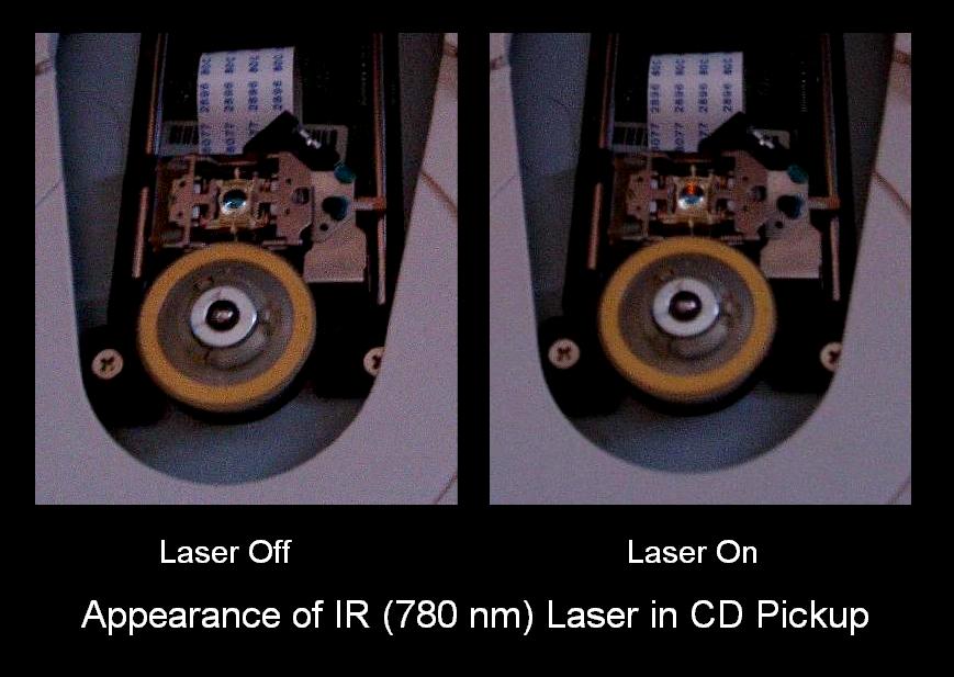
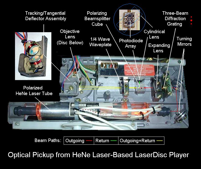
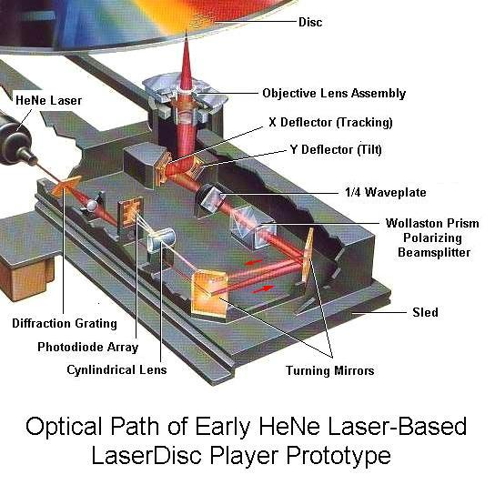
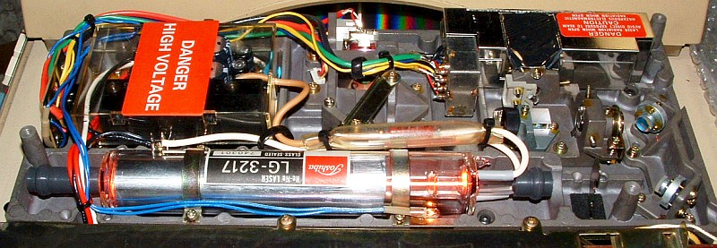
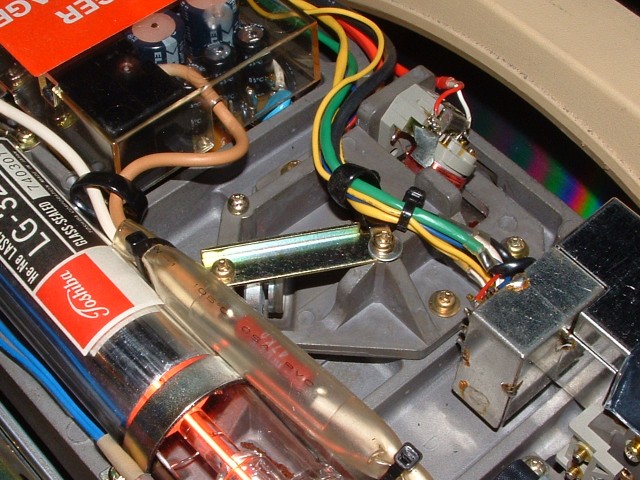
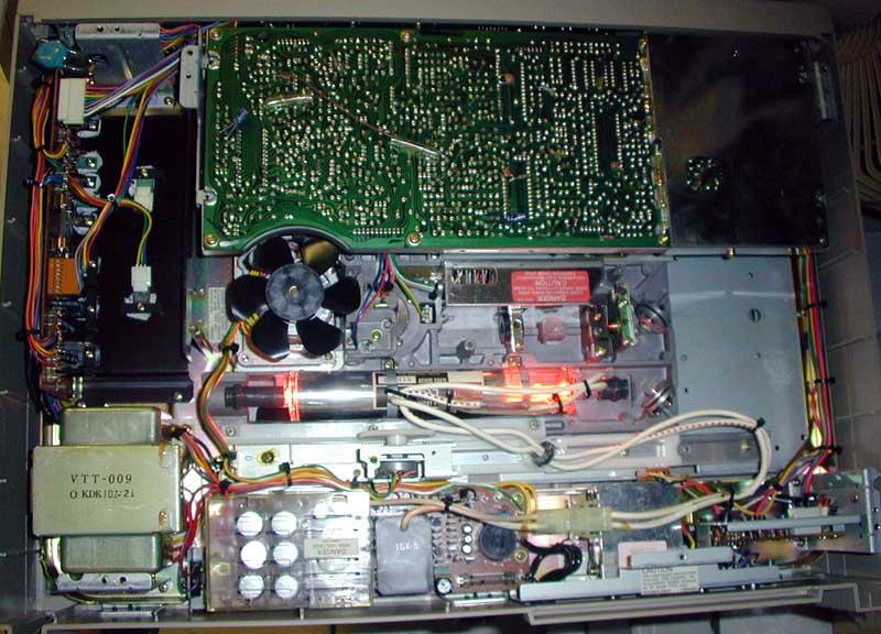
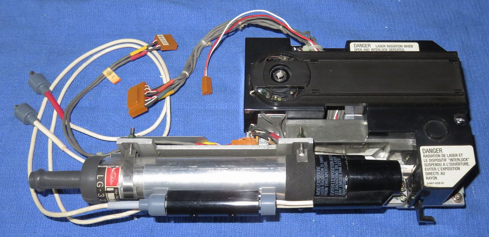