High power DPSS lasers use lasing crystals in the form of rods pumped by radially arranged arrays of high power laser diodes. Since just one of the diode arrays alone would likely break the budget of an individual, what we consider primarily in this chapter are much more modest - typically a chip of Nd:YVO4 a few mm on a side and a mm or so in thickness pumped by a single bare (on heatsink), packaged, or fiber-coupled laser diode. Intracavity frequency doubling is done with a small block of KTP with the various mirrors either combined with, or separate from these. This basic configuration can easily generate over 100 mW of green light. The Nd:YVO4 and KTP are available individually or in 'hybrid' modules (also called composite crystals or composite crystal assemblies) from suppliers such as CASIX. Their "DPM" series combine the Nd:YVO4, KTP, and mirrors into a single unit for as little as $49 (quantity 1). See the sections starting with: Green DPSS Lasers using Hybrid Crystals.) Just add a pump diode and collimating lens and you will have the equivalent of a green laser pointer. Components may also be obtained from various laser surplus outfits and also show up on eBay from time-to-time.
Depending on sophistication, the pump laser diode may be mounted directly on the lasing crystal or have its beam passed through correction and collimating optics first. Thermo Electric (TE) devices may be used to regulate the temperature of the pump diode for general cooling and to temperature tune its wavelength to the optimum for the absorption band of the Nd in the lasing crystal (around 808 nm). Temperature control of the vanadate to keep it cool and happy) and KTP to keep it warm and happy to further optimize output power may also be desirable. If you are determined to generate more than a few mW of green light, all of these will be needed.
However, note that like the home-built pulsed solid state laser, constructing a DPSS laser truly from scratch is way out of the question onless you work for laser diode and laser crystal companies simultaneously. :) So, you may feel that a DPSS laser doesn't offer enough of a challenge or reward without being able to say you did everything from the the ground up. Building one for $10 is also probably not realistic unless you can salvage crystals and optics from a broken laser - the major components are still expensive (though slowly coming down in price). Having said all that, I do consider a DPSS laser to be worthy of home-built laser status - else I wouldn't have created this chapter!
Avoid eye contact with the direct or reflected beam. This is particularly critical for the 808 nm (Nd) pump diode wavelength which is almost totally invisible and the output of the YAG or vanadate crystal (1064 nm) which is totally invisible. Neither of these is eye-safe and at the power levels involved, can cause instant and permanent damage to vision. Higher power (e.g., above 5 mW) green output at 532 nm is also dangerous but at least you can see it!
808 nm: The typical pump diode will have a maximum output of between 0.5 and several WATTs. The light appears deep red but only 1/20,000th or less bright than an equivalent visible wavelength light source.
WARNING: The output beam of high power laser diodes with an attached microlens (or other collimating optics) is much better collimated than we are used to for laser diodes - closer to that of a "real" laser. The divergence is typically 10x4 degrees as opposed to 10x40 degrees for a bare laser diode. What this means is that both the direct beam and any specular reflections are MUCH more dangerous to vision even several feet away from the source. Even the reflection from a shiny IR detector card can be dangerous. This is especially scary for people who have become complacent working with laser diodes being used to beams that spread out to safe levels in a few inches.
1064 nm: As noted, this is totally invisible but for small DPSS lasers, is safely tucked away inside the cavity. With proper mirrors, very little 1064 nm light exits either mirror - they are both HR at 1064 nm. However, this can still be several mW or more even with high quality HR coatings. And, if you cobble together a cavity from mirrors that aren't optimal, much more collimated 1064 nm light could exit either end.
532 nm: Most of the green light will exit the OC-end of the laser but where the mirror on the vanadate crystal isn't coated HR for 532 nm, a fair amount will also exit the back of the cavity and bounce around the laser diode beam correction optics. However, this isn't much of a risk since it isn't in the form of a collimated beam anywhere. The output beam will be fairly well collimated and could be quite powerful. As the OC mirror or KTP is adjusted, power can go from zero to high enough to damage vision almost instantaneously.
Provide proper warning signs for both the laser radiation and high voltage. Keep pets and small children out of the area and make sure everyone present is instructed as to the dangers. The use of proper laser safety goggles for the specific wavelength(s) of your laser or indirect viewing methods such as the use of a CCD camera are highly recommended. Relatively inexpensive goggles designed specifically for the 3 relevant wavelengths of the green DPSS laser are available from many companies. One possible source is Spectronika. Ltd.. However, they are likely to be more expensive laser safety goggles for many other lasers. The primary reason is probably that they do have to be triple coated to cover the 3 relevant wavelengths - 808 nm, 1,064 nm, and 532 nm. The best ones will have high quality narrow band coatings to maximize the transmission of non-laser wavelengths and thus brightness. Simple dye-absorption type materials would not work well. You get what you pay for!
For more information, see the chapter: Laser Safety. Sample safety labels which can be edited for this laser can be found in the section: Laser Safety Labels and Signs.
As a comparison, in Version 1.85 or higher, there are also photos of a pair of high quality green DPSS lasers from Coherent, Inc., under "Coherent Diode Pumped Solid State Lasers". These are the Compass 315M rated 100 mW and the Compass 532-200 rated 200 mW.
See Organization of Basic Green DPSS Lasers for examples of the major components of typical green laser pointers and a medium power (50 to 100 mW) green DPSS laser system similar to the 80 mW unit shown in the Laser Equipment Gallery (Version 1.74 or higher) under: "Assorted Diode Pumped Solid State Lasers". Either of these would be a suitable home-built DPSS laser. The second generation pointer (upper right diagram) is not much more than a CASIX DPM hybrid crystal positioned next to an 808 nm pump diode with a microlens to improve the pump beam shape (but that could be left out for the a first version). An IR filter and collimating lens completes the unit. Such an approach may be the best choice for your first green DPSS laser. See the section: Super Simple Green DPSS Laser using Hybrid Crystal.
The medium power green DPSS laser uses closed loop TEC control of both pump diode and cavity temperature and a possibly overly complex set of pump beam correction optics (actual lenses shown are basically just guesses!) which could be simplified considerably. See the section: A HREF="lasercds.htm#cdsrd801">Description of the 80 mW Green DPSS Laser for a listing of the specifications for the major components.
For an example of a higher power and more challenging laser, see the very preliminary diagram of a Typical Home-Built DPSS Laser Assembly. This should be capable of between 100 mW and 2 W of green output. However, any of the higher power versions, at least, would be quite complex and expensive projects. In addition to all the precision machining, the cost of the pump diode, large vanadate and KTP crystals, and optics, there would need to be considerable electronics: The driver for the pump diode, the pump and vanadate TECs with their controllers, and the KTP heater and its controller. Note that while the beam correction optics shown in this diagram use anamorphic prisms, that approach will only work for up to perhaps a 2 to 4 W pump diode. For higher power using a wide stripe pump diode, bar, or array of bars, either a fiber-coupled or fiber bundled diode laser source with output focusing optics, or the use of a lens duct and HR mirror on the vanadate crystal would be needed.
To see how the "big boys" do it, see the Ring Cavity Resonator of Coherent, Inc. Verdi Green DPSS Laser. A photo of the inside of a Verdi cavity can be found at Coherent Verdi DPSS Laser Cavity with Components Labeled. The ring cavity provides robust single mode operation at high power levels as well as nearly 100 percent efficient extraction of the doubled (green) output due to the unidirectional beam circulation. Verdi lasers now exist up to at least 18 WATTs!!! I want one. :)
Photos of the interior of a Coherent Compass 532-200, a lower power green DPSS laser than the Verdi also using a ring cavity can be found in the Laser Equipment Gallery (Version 1.86 or higher) under "Coherent Diode Pumped Solid State Lasers". The 532-200 is rated 200 mW, but can produce at least 400 mW by increasing current to the pump diode (at the expense of diode life expectancy). The last photo in the sequence is a closeup of the cavity and output optics showing the actual beam path.
Here is the general description covering low, medium, and high power DPSS lasers. See the section: Component Selection Chart for Home-Built DPSS Lasers for an idea of what is required based on output power.
Frequency doubling crystal of KTP inside cavity. Typical size between 2x2x2 mm and 3x3x10 mm.
I recommend wiring a 0.01 uF capacitor, 100 ohm resistor and 1N4148 or fast recovery diode (in reverse polarity, if there isn't one present already) in parallel across the pump diode permanently. These components will help to protect it from ESD and stupid mistakes.
For something to rival the pros, see Typical High Power Green DPSS Laser Optical Path, a side-pumped YAG based Green DPSS laser capable of truly show stopping power. Finally, information on cavity construction of high power DPSS YAG laser with a linear resonator is provided by Bob and hosted by LaserFX in Laser Construction - Pump Cavity. I expect this page to be added to on a regular basis.
However, perhaps, building one of the more modest designs first would be a good idea - this would set you back the price of a nice used car just for the pump diode arrays, crystals, and optics. Throw in the resonator machining, electronics, and what else is required to turn it into a useful laser and you could be motoring around in style. :)
However, Melles Griot's low-to-medium power high quality green DPSS lasers now use composite crystals similar to CASIX's but of their own design optically contacted without any glue between the crystals (the DPM010X crystals are glued), so there is nothing to degrade. Unfortunately, there is no chance of getting these crystals for home use. :( VLOC also manufactures composite crystals that may be capable of very high output power - over 1 WATT of green - but you don't want to ask the price. :) So, what about somehow separating the two crystals by dissolving or softening the glue to eliminate that problem? Even if this could be done, just handling the individual pieces would be a challenge. The larger of the two CASIX composite crystals is 2x2x2.5 mm total dimensions; the smaller, 1x1x1.5 mm. I'm not about to try separating my CASIX crystal but attempting this with other types of composite crystals using an acetone soak was not promising. By the time the glue softened enough for the crystals to come apart, the mirrors had deteriorated to the point of being useless. Also, assuming you could get the two pieces apart without damaging them, what remains are two surfaces which aren't AR coated. Without index matching of some kind, there would be excessive loss and instability from the reflections at the two uncoated surfaces. See the section: Joachim's Comments on Lasers Using Composite Crystals, below.
(Note: Should you acquire an optically contacted crystal (possible sources: Cristal Laser and VLOC), while there is no glue in between the crystals to be damaged by excessive intracavity power, there can still be problems with handling and excessive pump power popping the crystals. Since only the edges are glued, very small optically contacted crystals tend to fall apart either on their own or when pumping causes the central parts to expand. Thus, there still may be an upper limit below the damage threshold of the vanadate. The only way to determine it non-destructively is to check the specifications.)
CASIX has now started selling composite crystals that may be optically contacted rather than glued at about the same prices as they were previously charging for the glued crystals. The DPM1101 and DPM1102 ($99 and $129, respectively, but these prices will no doubt drop quickly) should not have the stability problems and power limitations caused by the face glue of the DPM010X composite crystals. Go to CASIX, then "Products", "Crystal Products", "DPM", "High Power DPM Crystals".
Note that originally, the CASIX Web site stated that the DMP110X composite crystals were diffusion bonded but it is not known if this is true of all of these crystals. Some have been shipped with "splints" on two sides, presumably to hold them together more securely, something that shouldn't be needed with diffusion bonding. Other information has also suggested that they are optically contacted.
See Super Simple Green DPSS Laser. (The magnifications - 1X, 3X, 8X - assume a 100 dpi display or printer.) The mounting shown for the pump diode and crystal are just suggestions - you don't have to use the same really tiny plates and screws that are shown. Note the size of this laser at 1X! Almost anything that puts the output facet of the pump diode almost in contact (but not touching) the vanadate will work.
For experimentation, a very simple power supply is sufficient for the laser diode driver (though a proper driver should be added to make them more user friendly and fool-proof if put to actual use, even if for demonstrations or as that green laser pointer with visible guts. :) My test power supply consists of a low voltage power transformer, rectifier, and filter capacitor, controlled by a Variac with an 8 ohm power resistor in series with the laser diode and a meter to monitor current. With care (always turn the current down before powering up/down, make sure all connections are secure), this can safely drive these diodes with no possibility of overshoot/reverse polarity on power cycling and good immunity to power spikes. Compared to our "killer laser diode driver", a very expensive commercial unit that has obliterated more than one very expensive diode laser due to some intermittent circuit problem, this bare bones driver is quite reliable!
My initial tests of the DPM0101 and DPM0102 were using a fiber-coupled 808 nm pump. In a nutshell, they work great! With the fiber's 100 um core diameter and no beam correction, the thresholds for both were similar and slightly higher than with my discrete (green laser pointer guts) setup using a GRIN lens. However, it was possible to obtain much higher output power - probably 10 or 15 mW - at a pump power of around perhaps 300 or 400 mW (this with the non-polarized output of the multimode fiber which reduced efficiency by about 50 percent compared to a polarized pump beam that matches the preferred axis of the vanadate). The beam shape was actually quite decent even with the planar-planar resonator of the hybrid crystals. (More below.)
One interesting characteristic for the DPM0102 was that as the pump power was increased, output power climbed slowly for awhile and then increased after a time delay rapidly to a much higher level. I suspect that this may be due to heating effects - either thermal lensing of the crystal or improved phase matching at higher temperature - but don't know for sure. The DPM0101 didn't exhibit this behavior - output power increased smoothly with pump power. But it didn't sustain the highest power for more than a couple seconds - the power decayed to a lower level. However, this was reversible by shutting down and letting the crystal cool off. Both these effects may have been related to alignment - my setup, or lack thereof, couldn't really be adjusted precisely.
I expect that even simple pump beam shaping to reduce its diameter in the vanadate will result in higher efficiency and greater output for the same pump power. I haven't done any precise measurements as yet but will do so soon. However, I don't intend to push my luck on output power though knowing the problems that others have experienced with damage to the glue used to bond the two crystals together.
Even Simpler Instant Green DPSS Laser is a photograph of this unit lasing with a power output of about the 10 mW. (For an idea of size, the threaded holes of the optical table are 1 inch apart.) The closeup shows the major components. The pump diode is at the left wired with a reverse polarity protection diode and bypass capacitor. The DPM0102 hybrid crystal is mounted on a miniature three screw adjustable platform which provides for fine control of pitch, roll, and height. It is held snugly, but gently, under the aluminum bracket amidships with its rear face positioned as close to the pump diode as possible without touching. The "pitch" (I.e., tilt) adjustment is for vertical alignment; loosening the bracket and/or the screws that fasten the pump diode to the baseplate allows horizontal alignment of the pump beam with the crystal. The screws marked "roll" are really only to allow the entire crystal/platform to be raised or lowered - slight rotation about the beam axis has no effect of any consequence (but may come in handy for future applications). Although the laser cavity is formed by the faces of the crystal and thus there are no adjustments (!!) for actual mirror alignment, it's still important for the crystal to be fairly well aligned with the diode's output beam (though a huge $500 Newport mount isn't needed). Due to reflection of the backward going green beam from the front facet of the pump diode, there will be ghost spots when alignment isn't correct. The orientation and distance between the spots provide a clear indication of which direction to move. In the case of my diode, the chip appears not be mounted particularly perpendicular to the plate's centerline so it needs to be skewed to make the output beam come out straight when the ghosts spots merge!
An interesting characteristic of this setup is that above some minimum power level, not very much green light seems to come out the back of the crystal (unlike my green DPSS laser using discrete crystals and optics where everything behind the vanadate literally lights up like a Christmas tree). At low power, there appears to be significant back scattered green light. This actually appears to reduce in intensity as the pump power is increased - but only if the crystal is oriented so that the polarization of the vanadate matches the pump diode. Otherwise, the back scattered green light continues to increase in brightness. In reality, the back scattered light is probably just not increasing in brightness as fast as the main beam so it appears to decrease. Got that? :) I don't know whether this is some non-linear effect with respect to the relative amount of forward/backward conversion in the KTP, simply changes in mode structure resulting in more of the backward green hitting the front facet of the pump diode and being reflected forward, or something else.
Even without any pump beam shaping, the output beam profile is still TEM00 and reasonably circular at low power. At higher power it may split into 2 or three modes though I haven't really determined the conditions for this to occur. Since my pump diode is quite high power (probably good for 2 W at least with a large stripe width), its threshold is much higher (about 700 mA) than the 100 to 250 mW diode recommended for use with these composite crystals, so I don't really know how the efficiency of this rig compares to using the fiber-coupled pump but it seems to lase green with very little pump power (checked by the brightness of the pump light) and output power increases quite rapidly with increasing pump power.
Another incredibly super simple instant design is shown in Green DPSS Demo Laser using CASIX DPM0101 Composite Crystal. The pump diode is a bare chip soldered to a brass plate with the top contact attached using silver conductive Epoxy. The DPM0101 is glued into a slot in its own brass plate with 4 screws and lock-washers for adjustment. I have built a unit similar to this for somone who needs to show non-laser types how a basic diode pumped microchip laser works. It will be mounted in a Plexiglas box with a magnifier. For the power supply, I used the Roithner EU38 laser diode driver with a filtered 4 V linear voltage regulator preceeding it. Input power is from a 6-9 V wall adapter. See: Green Demo Laser Power Supply Using EU38. The complete system is shown in Green Demo Laser With Power Supply. The dimensions aren't quite identical to the diagram, above, but close enough for government work. :) The reason for the ghost spot is that the laser diode chip is mounted a bit skewed on its heatsink so the reflection of backward going green beam from the KTP doesn't reflect on-axis.
There are some disadvantages to this approach. With the batch fabrication technique (see below), both mirrors are planar which means there is little control of transverse mode structure (though with a well shaped pump beam, this doesn't seem to be a problem). And there is that problematic glue used to bond the vanadate and KTP together which is one of the prime limitations on extended operation at high output power. (This only applies to the DPM010X; the new physically similar DPM110X hybrid crystals are optically contacted which should eliminate this problem and allow for much higher continuous output power operation.) However, these deficiencies are more than made up for by the immediate gratification of getting bright green light with without the hassles of handling, mounting, and aligning individual fragile crystals and optics.
DPM crystal specifications:
These are based on my expectations and observations. I have not actually made precise measurements:
Maximum output power:
This is one of those things where there are apparently no hard answers (or at least no one is talking) so much of the following is just my opinion. According to CASIX, the maximum recommended input pump power is around 300 mW resulting in a lifetime of at least 5,000 hours (whatever that really means). The first person I asked at CASIX didn't specify output power but someone else suggested that 10 mW max was a good number. Given that both of these DPM crystals are intended for green DPSS laser pointers, I would assume that a continuous output power of 2 or 3 mW for the DPM0101 and 5 mW for the DPM0102 will be safe for long term reliability. I know it's tempting to drive these things much harder - I've seen over 35 mW (limited only because I didn't wont to fry my samples) and others have achieved 100 mW or more. However, there are both thermal considerations as well as damage to the cement used to glue the vanadate and KTP which may limit use of such high power for more than short periods of time. From conversations with other crystal venders (but not CASIX) using similar adhesives, operating at a 30 mW level may result in damage after a few hours while at 5 mW, there may not be any damage after thousands of hours. Note that since intracavity power density also depends on factors like pump spot size and shape, there won't be a single number for maximum output power. Until more is known, just assume your mileage may vary and don't press your luck too much. :) Please send me mail via the Sci.Electronics.Repair FAQ Email Links Page if you have any additional information or personal experiences using these or similar crystals.
Operational considerations:
Note that with the non-polarized multimode fiber, these lasers run with multiple longitudinal modes even just above threshold since the light that isn't polarized in the proper direction isn't absorbed as quickly in the vanadate resulting in excitation throughout its length. This probably doesn't matter for most applications but may be a consideration if the intent is to build a single frequency laser.
Beam characteristics:
Which one to get? While the DPM0102 is more expensive than the DPM0101 ($49 versus $99 in November, 2002) it is easier to handle and may possibly be more robust, and is potentially easier to cool and thus may be capable of higher output power. And, should one spot of the glue become damaged from overzealous experiments in pushing the envelope, there are plenty of alternative areas to use just by shifting the pump beam location. However, with the introduction of the DPM110X optically bonded hybrid crystals at reasonable prices (see below), the use of glued crystals will only be justified in extremely cost sensitive applications. So, go for the DPM1101 or DPM1102 instead.
When the DMP110X crystals were introduced, the following (slightly paraphrased) appeared on the CASIX product announcement page:
"Optical bonding is based on diffusion. The crystals are permanently bonded by heating to a high temperature under pressure resulting in a chemical exchange of molecules at the interface. The resulting monolithic unit should be stable with respect to high and low temperature storage, temperature cycling, impact and shearing, solvents and other chemical attack. They can work in high vacuum and under intense radiation."
Since these hybrid crystals can be fabricated in large pieces and then diced up into their final size, costs should be much closer to those of glued crystals. The cost of optically contacted crystals will never be very low since they must be assembled individually. In fact, the initial prices for the DPM1101 and DPM1102 ($99 and $129) are similar to the previous prices of the DPM0101 and DPM0102 (which have now dropped to $49 and $99). Given the advantages of the optically bonded approach, there is little reason to even consider glued crystals unless price is the absolutely overriding concern.
However, it now appears as though the DPM110X crystals are indeed optically contacted and not diffusion bonded. This is somewhat confirmed by the existence of the reinforcing strips. If so, most of the advantages are still present, but how they can be fabricated at low cost is a mystery. And, even with the reinforcing strips, the robustness of optically contacted composite crystals is questionable since delamination from the stresses induced by thermal stress (in particular, thermal lensing) can be a problem with this approach.
See the section: Some Tests of the DPM1101 and DPM1102 for some more info.
Note that the output of the multimode fiber is non-polarized. Thus, the portion of the pump light that matches the preferred polarization axis of the vanadate will be absorbed in a shorter distance (100 or 200 um assuming 3 percent doping for the DPM0101) of the vanadate while the other light will have a much deeper penetration - possibly resulting in a significantly higher threshold and lower output power (for a given pump power) if a substantial portion doesn't get absorbed at all.
Here are some observations using the fiber-coupled pump, far from complete:
I later tested the same crystal with a Spectra-Physics SCT100-808-Z1-01 open heatsink laser diode (1 W, 100 um stripe width) temperature tuned for 808 nm. The diode was positioned just short of touching the DPM0101 with the crystal oriented for optimal absorption. The lasing threshold came down to about 100 mW with good beam quality. I did not look at the spectral behavior but assume it to be similar.
Diane has built a nice little laser around the DPM1101 and performed more quantitative tests which are documented on her Web site at Diane's Xenotim Laser. She comments that this isn't a true home-built laser, which is certainly true compared to her "Querflvte" ("German Flute") pulsed multiple gas laser, but it's still nice and worthy of the home-built classification! :)
I would have expected the diffusion bonding technique (which is what I assumed these to be based on the CASIX Web site) to yield a very robust composite crystal. However, the samples I received had pieces of glass or other material glued on two sides apparently to provide reinforcement so they don't fall apart. This is why the size specification has a smaller clear aperture than that of the glued crystals. So, the top view looks something like this:
                     ________________________
                   _|________________________|_
                  |       |                    |
                  |       |                    |
                  | Van-  |                    |
         Pump --> | adate |         KTP        | --> Green Output
                  |       |                    |
                  |       |                    |
                  |_______|____________________|
                    |________________________|
Apparently, some samples of the DPM1101 and DPM1102 received by other people do not have the splints. Perhaps CASIX was being overly careful on the first few batches. I did order mine just after the product announcement. However, since they are actually optically contacted, this makes sense. The CASIX Web site no longer lists the method used. If this is so, whether for technical reasons or something else, I don't know. I have my suspicions though.
The lasing tests on the DPM1102 were initially performed using a Sony SLD322V pump diode (808 nm, 500 mW max, 50 um stripe width) with a pair of 12 mm f/1 lenses for beam focusing. The pump assembly was mounted on a Newport XYZ micropositioner.
The lasing threshold was relatively low (about 200 mA). However, a nice TEM00 beam was produced only near the top of the crystal - the classic "sweet spot problem".
Increasing pump power didn't produce proportionately more output power as would be expected (or at least desired). The power seemed to remain steady at a few mW. Granted, I'm not doing anything yet to cool the crystal.
I next tried a DPM1101 (1x1 clear aperture) with a fiber-coupled 808 nm pump (100 um core) whose output fiber was mounted on a Newport XYZ micropositioner. The performance of this estup was much better than that of the DPM1102 producing a nice TEM00 beam from lasing threshold to 50 mW or so which was the maximum I have pumped it so far. (I do not know the exact pump power but expect it to be around 500 mW at the fiber tip.) There was only a slight variation in output power with respect to pump position on the crystal (minimal "sweet spot problem"). The output power increased smoothly with respect to pump power (which is not something I've seen in most of Casix's glued crystals). When pumped to produce about 20 to 30 mW, the output remained quite constant over the course of an hour (eyeballed).
After better success with the DPM1101, I replaced it with the DPM1102 but used the same fiber-coupled pump setup. In this case, the results were somewhat better than with the Sony diode. While there was still some non-uniformity of power output with respect to pump position, it didn't seem nearly as severe. The output power increased smoothly with pump power and was of similar intensity to that from the DPM1101. I've run this setup now for at least 10 hours at a 50 mW output power level with no significant change in behavior. The only cooling is from being in contact with an aluminum plate on which it is loosely clamped.
So, my opinion is that the two crystals do behave in a somewhat similar manner when the pump is the same.
More to follow.
The simplest non-GRIN lens option for a pump diode in a can or other package with a window is to use a pair of short focal length positive lenses. The first lens collimates the beam while the second lens focuses it into the crystal. For the wide divergence of the bare diode, these typically have to be f/2 or f/1 lenses. In essence, this is a relay lens system to permit an image of the inaccessible diode stripe to be placed in the crystal with low losses. By selecting the focal lengths of the two lenses and possibly allowing the beam between them to be not quite parallel, the spot size can be changed (usually it will be desirable to reduce it). For example, using a 12 mm diameter, 12 mm focal length lens (12/12) feeding a 6/6 lens (the beam between them would have to be slightly converging), the spot size of a 100 um stripe width 1 W diode can be reduced to around 50 um.
For more, see the next two sections.
Therefore, attempting to swap in some undocumented high power diode found on eBay to boost power of a DPSS laser is at best a crap shoot even if its wavelength and electrical parameters are known. :)
The typical stripe width of a LD is roughly proportional to its maximum output power. The beam from a 2 W LD will be 4 times as bright as one from a 500 mW unit only if their stripe widths are the same. However, the typical stripe width for a 500 mW LD is 50 um while that of a 2 W LD is 200 um or even 400 um. The stripe width can be determined experimentally by projecting the LD beam onto a screen through a short focal length positive lens producing a focused image of the stripe. The stripe width of the LD will be the ratio of the distance from the lens to the LD and from the lens to the screen multiplied by the image size on the screen.
(From: "Joachim Mueller" (JoachimMueller@swol.de).)
I have tried to work with the parts from CASIX. I ordered some of the DPM-crystals from casix separated (not glued together) and did some experiments with them. The middle surfaces, which normally are bonded together, are only polished - there are no coatings. When only sticking them together, the optical loss resulting from reflections is too high. Only a very weak green beam was visible. One solution is using index matching gel (used in fiber optic technology). This material is able to operate under very high power-density with no damage. The problem is handling the 2 small crystals and keeping the matching gel free from air-bubbles. Also the 2 parts have to be aligned to the proper angle to match the polarization. It was a a lot of work putting the 2 parts together. Another problem is that CASIX can not test the crystals like they do with complete modules. If the polish is not perfect to form a parallel resonator, the result in green light is bad. After spending a lot of time on this approach, I came to the conclusion, that it is not a good way to save money. I think using discrete standard crystals is the better way to build a good working laser.
In fact, I worked for 2 years trying all kinds of microchip modules from $99 to $1,000 each. The result is, that I stopped all work in this direction. Nearly all manufacturers (and users) of microchip lasers had trouble with it. Most of the laser manufacturers went back to using traditional spherical resonators. One of the problems of the modules is, that the beam quality is never quite as good and that there is no second source for such a part. Getting a good module is like playing the lottery. The chance to get the next module with the same characteristic as one you've tested is low.
And, except for the special case of mass produced green laser pointers, microchip technology is expensive. For the same amount of money you can get the parts for a laser made from discrete parts. The vanadate + KTP + OC mirror will cost below $200. Beam quality of a discrete is better. Modules work with a very short cavity, a few millimeters. This increases divergence. It is nearly impossible to get a beam of diameter of 1 mm and less than 1 mR using a microchip module. Pumping a CASIX module with 1 W or more gives a divergence of 10 to 15 mR. Reducing this to 1 to 1.5 mR requires a 10X telescope which enlarges the beam to 2 mm or more. There are some modules with better beams, like the LSB-modules from Russia. They have about half the divergence of a CASIX module but cost at least double the price. (More below.) The only advantage of a module is getting relative high output power the easy way. But what is better: 100 mW of a 2 mm thick 1.5 mR beam or 50 mW of a 1 mm at 0.5 mR? When I see a thin low-divergence DPSS-laser beam, I know that this is NOT microchip technology. If make the effort and spend the time making a stable mechanics for adjusting the optics the results with using discrete parts will be much better.
I�m currently working on a discrete plane-parallel resonator (using HR@1064-coated KTP). It is like using a separated crystal module with the inner surfaces AR coated. My cooperation with a Chinese crystal manufacturer allows me to optimize coatings, materials and other characteristics. First results: 100 mW at 5 mR divergence without any beam optics. This configuration will lower the number of parts and makes me free from adjusting the orientation of the KTP inside the cavity. Moving the pump spot in XY direction does not affect the cavity alignment (This is a big problem when using a spherical resonator). Once adjusted, the cavity is a kind of "big module" and is replaceable inside the laser without the need of readjusting all parts. I'm now thinking about a simple and reliable mechanical adjustment-stage. Then it could be possible to offer the cavity without diode ready-to-use, just mount the thing to a TE-cooler, pump it and add output optics. Like a module! I think this cavity will cost a user around $350 and will allow building a powerful DPSS-laser without the trouble of mounting crystals and glued modules.
There are 2 companies I know making LSB based microchip lasers. One is in Germany and the other is in Russia. The Russian version (from the "Science and Technology Center FIRN" is in a metal housing constructed for low pump power (1 to 2 W). The German version (I forget who it is from) is 3x3x2.5 mm unmounted and better to cool. I tested both versions, but was not happy with the quality and the price ($400 to $500). The LSB itself has a very high efficiency. With the Russian parts, 200 mW at 1 W of pump power was possible. It could be more, if they would use higher quality KTP. The manufacturers told me a maximum pump power of about 3 to 5 W, so 1 W output is theoretically possible. But in reality, trouble starts at pump power greater than about 1.5 W. It had some coating defects and thermal management is also critical. LSB is a very bad thermal conductor. I know that a group of scientists reached 1 W green with a module under optimum conditions but they didn't say anything about the lifetime of their microchips. I think LSB is a good solution for a maximum output at low pump power (1 W). It would be interesting to use LSB-chips in a standard setup with discrete crystals. Unfortunately, I have no single piece of coated Nd:LSB available. :-(
(From: Joe Farina (nospam@newsranger.com).)
There is a paper which might be worth mentioning. It was published in Optics Letters, Volume 19, Number 18, September 15, 1994: "Intracavity frequency doubling of a continuous-wave, diode-laser-pumped neodymium lanthanum scandium borate laser." Here is part of the abstract:
"...A simple plane-plane 3-mm-long resonator is formed by a coated Nd(10%):LaSc3(BO3)4 crystal and a coated potassium titanyl phosphate (KTP) crystal. The second-harmonic output power at 531 nm is 522 mW at 2.05 W incident pump power of the diode laser... The well-known chaotic power fluctuations of intracavity frequency-doubled lasers (green problem) are avoided by use of a short KTP crystal, between 0.5 and 2 mm in length."
 Power Output:          5 mW       20 mW      100 mW       1 W         5 W
-------------------------------------------------------------------------------
 Pump Diode (1)
  Maximum Power       100 mW      500 mW        1 W       10 W        50 W
  TEC Thermal Power     --          1 W         3 W       30 W       150 W
  Beam Correction     <-- uLens or None -->   Prisms    <-- Fiber-coupled -->

 Resonator (2)
  Type               <-------- Hemispherical ------->   <--- Long Radius --->
  Length                7 mm       15 mm       40 mm       80 mm     150 mm

 HR Mirror (3)
  Diameter              ---         ---         ---        10 mm      15 mm
  RoC                   ---         ---         ---       250 mm     500 mm

 Vanadate:
  Overall Size       2x2x0.5mm  3x3x1.2 mm  3x3x1.2 mm   3x3x3 mm   4x4x4 mm
  Doping Level          3%          1%          1%         0.7%       0.7%
  Side 1 Coatings    HT@808nm    HT@808nm    HT@808nm    HT@808mn   HT@808nm
                     HR@1064nm   HR@1064nm   HR@1064nm   AR@1064nm  AR@1064nm
  Side 2 Coatings    AR@1064nm   AR@1064nm   AR@1064nm   AR@1064nm  AR@1064nm
  TEC Thermal Power     ---        0.5 W        1 W         4 W       20 W

 KTP (4)
  Overall Size        2x2x3 mm    2x2x5 mm    2x2x5 mm    3x3x7 mm   3x3x7 mm
  Type               <------------ Flux Grown -------->  <-- Hydrothermal -->
  Side 1 Coating     AR@1064nm   AR@1064nm   AR@1064nm   AR@1064nm  AR@1064nm
  Side 2 Coating     AR@1064nm   AR@1064nm   AR@1064nm   AR@1064nm  AR@1064nm
  Heater Power           ---        0.5 W       0.5 W       1 W        2 W

 OC Mirror (5)
  Diameter              5 mm         5 mm         5 mm      10 mm      15 mm
  RoC                  10 mm        20 mm        50 mm     100 mm     200 mm
  Side 1 Coatings     HR@1064nm   HR@1064nm   HR@1064nm   HR@1064nm  HR@1064nm
                      AR@532nm    AR@532nm    AR@532nm    AR@532nm   AR@532nm
  Side 2 Coatings     AR@532nm    AR@532nm    AR@532nm    AR@532nm   AR@532nm
Notes:
For up to 10 mW (possibly even a bit higher), the use of a single mode pump diode with a GRIN lens or conventional beam correction optics may result in the highest efficiency. In one test I did, the same vanadate microchip laser (similar to a green laser pointer) that required 50 to 75 mW to reach threshold with a bare or fiber-coupled 1 W multimode laser diode would lase at something like 10 mW of pump power using a focused single mode diode! However, single mode diodes are only available up to 100 or 150 mW and are very expensive.
Diodes like this are also available with a fiber (cylindrical) lens attached to collimate the fast axis. This improves the spot shape if not using beam shaping optics and makes focusing with a GRIN lens more efficient. Spectra-Physics won't sell these in less than 5-packs and their price is somewhat higher) but they may be available from other sources.
The effective cavity length should be just a bit smaller than the RoC of the OC (output) mirror to assure stability in this hemispherical resonator. Since the intracavity beam is diffracted when entering and leaving the vanadate and KTP crystals (and these have a high index of refraction of around 2.2 and 1.9, respectively) the actual cavity length will be slightly longer than if they weren't present, about 2 or 3 mm in this case. So, start with the distance from the pump-side of the vanadate to the OC mirror of about 48 to 50 mm for a 50 mm RoC OC. The KTP should be close to the vanadate to take advantage of the small beam waist (and maximum power density for best doubling efficiency).
No, you can't get these out of a CD player (even 1,000 CD players). :)
Laser surplus places like MWK Laser Products may sell high power laser diodes. However, in many cases, they are pulls from equipment near end-of-life with output power that is way down from new part specifications. For example, a diode spec'd at 20 W may only produce 0.5 W at some ridiculous maximum current. These are probably not terribly useful for incorporation into a serious DPSS laser. (A 20 W diode also has a very long emitting aperture which would make beam shaping very difficult especially if all you can get out of it is a half watt!)
High power laser diodes also turn up on eBay from time-to-time (some are from MWK who goes by the eBay ID hene1). Without a guarantee, there is really no way to know for sure about the output power, remaining life, or if the device works at all. Search for "laser" and "diode".
The companies below are all manufacturers or suppliers of high power laser diodes, laser diode arrays, laser diode bars, etc. But the chances of a private individual getting any free samples or diodes at a discount from them are slim to none (probably none).
It appears as though Thorlabs sells some IMC high power laser diode bars (20 and 40 W at least). What's interesting are the prices. Boston Laser, Roithner, and others also list some prices. The prices are all somewhat depressing. :(
Here is info on some manufacturers/suppliers known to be willing to sell in small quantities:
When ordering laser diodes, if possible, specify a center wavelength range which results in optimal absorption in your laser crystal (typically 808 to 810 nm for vanadate and YAG). Otherwise, they may just send you diodes that are 804 nm at full power - even shorter wavelength for lower power. They may cost a bit more but is well worth not having to heat them significantly (which also reduces their life expectancy) to center the wavelength at 808 nm for maximum absorption. A longer wavelength is almost always better since cooling to shift it 2 or 3 nm is no problem (0.3 nm/°C). Also keep in mind that the wavelength spec is usually listed for rated power. If run at reduced power, it will be somewhat shorter.
Also see: K3PGP's Laser Diode Manufacturers and K3PGP's Laser Diode Specifications maintained by K3PGP (Email: k3pgp@qsl.net). (This is a listing of the database that used to be on the Thorlabs Web site.)
Note that more and more laser diodes are showing surplus and on eBay. The key to not being disappointed is to very carefully check out the seller both in terms of previous sales (e.g., Feedback rating on eBay) and their knowledge of the devices and where they came from. I also have a few laser diodes for sale. See Sam's Classified Page.
Laser diode drivers:
While it's possible to build your own laser diode driver, given that the laser diode (or array or bar or bars) probably represents the single most expensive component of your laser, buying a reliable driver is probably the best option. Laser diodes are very finicky and unless you can afford to blow a few in developing a home-built driver, a commercial unit is really best.
However, I plan to provide a design for a bare bones but reliable (I hope) constant current driver (2.5 A max) as well as a complete power supply using it in the near future. Stay tuned to this FAQ. :)
Various laser resellers and surplus dealers have low cost no-frill driver boards capable of 1 to 1.5 A at prices from around $10 to $50. These are almost certainly far-East imports which may or may not meet advertized specs. I probably wouldn't trust them to drive a $1,000 fiber-coupled laser diode without some testing to make sure they work properly.
The B&W Tek driver (BWD800) looks identical to the one from Roithner (EU38) so it's probably sourced elsewhere. I have used one of these to power the green demo laser described in the section: Even Simpler Instant Green DPSS Laser.
For higher quality modules and lab-style (and expensive) controllers, see:
The Wavelength Electronics modules have a good reputation (although I do have a blown one, cause unknown!) but are relatively expensive: around $300 for a 2.5 A driver. Lab style instruments from places like ILX Lightwave can run upwards of $10,000! And, they can still blow multi-$K laser diodes! Don't ask me know I know. :(
Laser and non-linear crystals and optics:
The following are some possible sources for laser crystals (e.g., Nd:YAG, Nd:YVO4), non-linear crystals (e.g., KTP, LBO), hybrid modules combining the lasing and doubling crystals, and optics (HR and OC mirrors, filters, etc.). Most probably won't give you the time of day unless you can convince them you are are associated with a company or university with deep pockets but others like CASIX and Roithner have prices for some items on their Web sites. These companies may have many more products than those listed below but these are the most relevant to the home-built DPSS laser. (Legend: LC=laser crystals, CC=composite crystals, NC=non-linear crystals, OP=optics, HM=hybrid modules. An HM is a CC mounted in a case with or without a driver.)
The following are manufacturers:
The following are resellers:
CASIX can provide everything but the pump diode for composite and discrete green DPSS lasers. The authorized distributor in the USA for CASIX is U-Oplaz Technologies, Inc. whose prices are the same as those listed on the CASIX Web site. I ordered the DPM0101 and DPM0102 from U-Oplaz with very responsive courteous service but watch out for the $15 S&H charge. The DPM0102 even came in a cute cloth covered Chinese box. :)
Roithner sells everything needed for a 100 mW-class green DPSS laser including pump beam focusing optics (required for use with their packaged laser diodes).
Optics component companies like Melles Griot, Newport, and others will have the various lenses and prisms needed for pump beam shaping.
Laser (resonator) mirrors:
While there are many sources of laser mirrors including places like CVI and Newport, their cost can run several hundred to over $1,000 - for a single mirror using ion beam sputtered super polished fused silica substrates. However, there may be no choice for use with higher power (e.g., Laserscope class) lasers. For low power DPSS lasers, the only reasonably priced source I know of at the present time for cavity mirrors is CASIX (see contact info, above). They have some of the types of planar and concave small radius mirrors required for low to medium power green and IR DPSS lasers.
Thermal control devices and supplies:
TEC manufacturers usually have loads of technical information for determining power input requirements, size, efficiency, etc. One example is the Tellurex Peltier FAQ.
Large electronics distributors may have some of these items, like TECs but their selection is probably limited. And, they certainly won't have supplies like indium foil (for cushioning laser crystals while providing good thermal contact) and low temperature solder (for mounting bare laser diodes, laser diode bars, and submodules). Some of this stuff shows up on eBay from time-to-time (Doesn't almost everyting? :) I recently came across some sheets of indium there but they were way too thick and the quantity was HUGE! Apparently, indium sheets, wire, gaskets, and other forms are common for cryogenic sealing applications but what you need is really just a fraction of a square inch of 0.001" thick indium foil). So, I wouldn't recommend holding your breath while waiting for the perfect deal at an auction. For these specific items, after reading what they would cost if purchased in the micro-sized quantities needed for DPSS lasers, see the special arrangement we have made, a few paragraphs from here.
(From: Richard Everett (reverett@newtonlabs.com).)
"I just got ten new surplus TEC devices in from BG Micro (Spring, 2002). These are NEW Marlow Industries DT12-4 (roughly 12 V at 4 A) 1.2x1.2 inch modules for about $6.75 each. This is really not a bad price, but here is the neat thing: You can buy the same module mounted on a heatsink with a little fan for $9.95. The cold side has a gold anodized metal plate with a prism shaped part sticking out of the middle of it with a hole tapped in on the flat of the metal prism shaped thing. It *almost* looks like this thing was designed for bolting on a c-mount diode. It is kind of funky, but it looks like it could possibly be made to cool a C-mount diode almost as-is."
Here are some sources for TECs, controllers, temperature sensors, accessories, and supplies, as well as application information on-line. However, some of these companies probably have a $100 or so minimum order and small quantities of specialty items like indium foil and low temp solder are bound to be exhorbitantly priced.
However, at least one company, Melcor has an on-line store with relatively reasonably prices for small quantities (linked from their homepage).
For a more extensive directory of manufacturers (new and surplus), device, materials, photos, diagram, and more, see Thermoelectric Peltier Device Information.
Analog Technologies will provide up to 2 free samples of their High Stability Miniature Thermistors. These appear to be ideal for both new and repair applications. (Their other products are too expensive for free samples though!)
TECs are often available surplus. Sometimes these are manufacturer rejects but should work fine, while many are just new excess stock. For example, All Electronics currently has several decent size ones in the $10 to $15 range (Winder 2005). Various types may also be found on eBay.
A couple of notes about benefits of indium over silicone heat sink compound: First, although indium's thermal conductivity is much lower than copper, it is still much higher than silicone or other types of grease-type fillers or pads. Another advantage is that it doesn't make a mess of everything, which is a definite plus in the middle of precision optics. :)
If indium foil isn't readily available but wire or another shape is, transform these non-planar shapes into foil is easy and quick. Dig out a smooth steel plate and rod from your junk drawer. Put a small piece of indium on the plate and use the rod as a rolling pin. In under a minute, this should produce a reasonable facsimile of foil since indium is very soft. It doesn't have to be perfect. You'll also wonder how they can charge so much for so little. :-) I assume tools made from something other than steel will also work but indium does stick to some, especially textured, materials.
Additional suppliers of TEC controllers (both lab style and modules):
For more information and suppliers than you could possibly want, see the Peltier Device Information Directory.
There are also TEC controller ICs if you want to roll your own and would rather not design it from scratch. For example, check out:
National Semiconductor has an app note on using an audio amplifier as a TEC controller. See their: Application Brief 118.
And, it's certainly possible to construct a useful TEC controller with discrete components (transistors, op-amps, etc.). This is particularly true where the drive is low power (as for a bit of KTP) or can be unipolar - only heating (typically for SHG crystals) or cooling (pump diode) is required. For simple examples of each type, see Low Power TEC Controller and Unipolar TEC Controller. However, high power TEC controllers with full functionality can also be constructed using any number of techniques.
(From: joefarina@my-deja.com.)
LakeShore has 2" x 2" sheets of indium foil (apparently a pack of 5) for $93. Go to "Products", "Cryogenic Accessories", "Solder". They also have a very low temperature (70 °C) solder called "Ostaloy 158" for $57. I don't know if there's a minimum order. (These items seem rather difficult to obtain in small quantity from other sources.)
I recently received some low temperature solder (93 °C) from Melcor but there was a $100 minimum order from them. (I couldn't find solder listed on their Web site. --- Sam) I also got a couple of TE coolers and some thermally conductive epoxy. My order didn't quite make it to $100, but they let it slide.
(From: Bob.)
There is a HUGE increase in price when you buy in small quantity. If you spent $1,000 with an indium supplier you may get 1,000 times as much material as if you spent $100, no exaggeration! When I called around for quotes on low temp solder I got back numbers like $50 a foot for a 10 to 50 foot quantity. I then asked for a quantity of 500 feet, and got quotes of around $5 a foot I don't know of any vendor willing to supply small quantities at a fair price. And, while there is a lot of indium floating around on eBay, unfortunately, pure indium has much too high a melting point (157 °C) for use in soldering assembled diodes, as the diodes themselves are often assembled with either indium solder or an alloy with an even lower melting point.
(From: Sam.)
Through an arrangement with Bob and Sterling Resale Optics, we will be able to provide small quantities of indium foil (for cushioning laser crystals with good thermal contact) and low temperature solder (for mounting laser diode bars and bare laser diodes on heatsinks). And, perhaps other similarly hard to find items in the future.
There are two types of special flux that can be used with the low temp solder. They can be identified by their color: The stuff for bare copper is lighter than the stuff for gold (which looks more like normal rosin-type flux). The type included with the solder will be the more reactive flux which may be used on either surface.
There is also a small fixed shipping charge. Prices subject to change without notice. Please no complaints, this is barely above cost when purchased in large volume and a teeny tiny fraction of the cost when puchased in the quantities you could reasonably use in a lifetime (if available at all).
IR blocking (and other) filters
The most important is the filter at the output of the laser to block potentially harmful 808 nm and 1,064 nm IR light. You may already have a piece of this in a defunct green pointer. Otherwise, suitable material is readily available.
(From: Kevin Criqui.)
The blue-green filters you typically find in laser pointers and small dpss systems is Schott BG38 or equivalent.
I think BG38 absorbs the IR so it can't be used for high power lasers. You can get dichroic low pass filters that reflect IR, but be careful not to reflect it back into the laser cavity. Check out Edmund Online Catalog of Precision Optical Components for "Hot Mirrors" and "IR Cutoff Filters".
Additional manufacturer links
(From: Robin Bowden (Rob@Radioeng.demon.co.uk).)
Only a few short weeks ago Greenie #1, the 532 nm DPSSFD laser was born. A 1 W Polaroid 9 mm 808 nm laser diode pumping a CASIX DPM0102 hybrid crystal through a GRIN lens.
Using 4 Alkaline AA batteries and switchable dropper - running the 808 nm diode at around 750 mW produced several tens of mW out. - Power dropped off fairly quickly after each battery change - see Voltage/Life curves for Duracell. It worked fine for 20 Hours and a similar number of battery changes.
Power hungry I built a switch mode PSU to run the pump diode at a constant current (Soft start over 50 ms - no overshoot to 1.21 A - current for 1 W out from manufacturers test data at 25C)
Using this PSU gave just under 100 mW out - time to pop balloons/cut black electrician`s tape. However, I was resigned to the fact that the adhesive used to glue the Nd:YVO4 to the KTP may not be able to cope with the high green power (experiments by Joachim Mueller showing black dot in adhesive after 40 Hours operation at 1.2 W pump).
Then last Sunday after 35 hours or so total use I tried to fire up Greenie #1. Output came up, fluctuated, and then went out for good.
The postmortem revealed that it was the pump diode that had failed!!!!!
The pump diode had a 50 ms soft start PSU with no overshoot. The diode had a 4C/watt heatsink which was at 12C-ish when I turned it on. The diode was also protected by 100 nF cap and 10 A Schottky diode for reverse protection while off.
Just one question: WHAT WENT WRONG?
Thoughts, comments, condolences and pearls of wisdom gratefully received.
(From: King Toebie (olx08152@online.be).)
Did you view the output of your switch mode PS on an oscilloscope? Diodes are VERY sensitive to overvoltage, and if you look on a wrong time-scale, you might miss the spikes. Take a simple pointer: The best way to kill it is to use a standard "stabilized" AC to DC converter - guaranteed to kill the pointer, batteries never will.
(From: Robin.)
Yep, did all that to the PSU before it came anywhere near the diode. Used four 1N4001 diodes as a dummy load.
I designed the switch mode PSU for less than 50 mA ripple at 1 A. (200 kHz ripple). It is a buck converter running at 200 kHz into two 47 uF Sanyo OSCON caps and a 10 nF 1206 (SMT) cap, then through 808 nm LD into a 1 ohm sense resistor for current control. Confirmed ripple using 100 MHz analog scope.
(From: Bob.)
A diode lasting only 20 hours sounds like classic diode infant mortality to me. There are tons of reasons why a diode may fail after only a few tens of hours. Improper soldering of the actual chip, a poor cleve during production, and contamination of the facets being the most popular reasons. A lot of vendors these days burn their single chip diodes in for 100 hours. Your source probably didn't do this. Either that or you just got unlucky.
As far as the other possibilities go, 50 milliseconds is fine for soft-start. If your power supply is intended for powering laser diodes and doesn't have any noise issues, then it wouldn't have killed it. A 4C/W heatsink is a little bit on the high side, I presume you were using a passive heatsink, I.e., no TE cooler. The main problem with that is heatsinks are rated when the heat source is evenly distributed over the entire surface. If you have a big heatsink and a small heat source you can get into problems with localized heating very quickly. Have you ever tried measuring the temperature of the diode itself? I once saw a guy build this huge elaborate air cooled heatsink for a custom 3 W, 660 nm laser diode that would cost about $10,000 to buy off the shelf. He was so proud of the design, but didn't think too much about the flow of heat. while he was running it in the lab. He complained about the wavelength of the diode being off, so I looked at his set up, and it was little more than a big block of passively cooled aluminum with a 5 mm laser diode can screwed onto it. The temperature of the heat sink was a nice 21 or 22 °C, but he almost soiled his drawers when I put a miniature thermocouple against the base of the diode package, and the temp readout displayed nearly 60 °C!
If you had reverse polarity protection on your diode, and a crowbar circuit to short the diode when not in operation, then there is next to no chance ESD or anything along that lines killed it.
I personally have never had a problem with back reflected green. Vanadate, especially highly doped vanadate in these small units is a very good green absorber, and this prevents nearly all of the green light from going back towards the diode.
I don't know if any of this can be classified as a pearl of wisdom, but you certainly have my condolences for what seems to be a case of diode SIDDS (sudden infant diode death syndrome).
(From: Sam.)
As far as back-reflected green, I guess you haven't seen the light show the DPSS laser I'm attempting to restore puts on, huh? The diode and all the correction optics light up like a Christmas tree from the green leaking out through the vanadate! You'd think that was the main beam path for the intra-cavity green. :)
(From: Robin.)
I would have preferred it if it was the PSU that caused the diode to blow - that would give more confidence that diode death would not happen again. Design defect I can live with, unknown infant mortality is harder to swallow.
The SMPS can be set for 0 to 1.25 A - set to 1.21 A for this diode. SMPS ripple is less than 50 mA at 1.2 A. I did use a passive heatsink (thick spreader with CPU heatsink and fan). The diode case never went over 35 °C - more like 15 °C when it failed. In the order of 30 to 40 mW at 532 nm going back to pump diode based 30% from rear of CASIX module. The diode is/was Polaroid MLD 808, 1 W, 9 mm - with full test data. Reverse polarity protected but no crowbar - but very unlikely to have ESD damage due to two 22 uF caps and the 10 nF cap directly across the diode.
(From: Dirk Baur (dbaur@medialas.com).)
There are different models of the Polaroid 808 diodes on the market. The first grade quality are quite expensive, the second grade you can get for a few bucks. Are you sure it was a second grade?
We used different Polaroid diodes, first grade, second grade at 660 nm, at 808 nm and so on. Not one of those made more than a few hundred hours. The first diode that died, was the first grade 660 nm with a micro lens inside. Maybe 30 hours, even with TEC cooling and antistatic equipment.
You are not alone!
(From: Joachim Mueller (JoachimMueller@swol.de).)
May it rest in peace.
My personal laser graveyard is full of Polaroids and also some SLIs and other nameless diodes.
An SMPS is not the best solution to drive a diode. SMPSs can produce short spikes in the microsecond range which are enough to kill the diode and are not easy to see with a simple scope. Capacitors across the diode are not enough to protect against spikes and never enough to protect against static discharge. When I buy a whole package (10 or 20) of diodes, these are sealed in an antistatic package, packed by the manufacturer. But when I buy a sample, the sales office or distributor puts it into a separate package. And I can tell you: Most of the problems I had with the samples! Never with the higher-quantity packages! So I think some salesmen don't take enough care when unpacking and handling the devices.
For example with SLI diodes, the sample died after 30 to 40 hours but the following 15 pieces run hundreds of hours without problems. I don't have such experience with Polaroids because I don't use them any more - too many 'samples'! Remember: If a diode gets a very small static discharge, enough to cause a very small defect, death can happen hours later. Morituri te salutant...
(From: Robin.)
They were fairly cheap - may have been second grade. I probably had 45 Hours out of the pump diode. I toasted a few business cards before integrating it into the DPSSL.
I bought 2 of these diodes from the surplus market. No undershoot spikes, designed those out, but did not include a crowbar circuit - could have been a mistake. Will add one for the other diode. I have the feeling that if I had posted here 2 months ago, saying that I intended to make a DPSSL from a Polaroid diode and a CASIX hybrid module I may not have built Greenie #1. However, I think that it was worth it for the few brief hours of 100 mW+. Biggest one before was 10 mW Argon.
I ordered flowers for Greenie #1, crowbar for #2. Oh, and a mount to move the crystal about when I put the 50 um black dots in it (assuming the pump diode holds out).
Fingers crossed.
(From: Joachim.)
When pumping with maximum 1 W and a normal (not microlensed) diode with a GRIN lens, the defect in the CASIX module appears much later. You should have at least 50 to 100 hours of green light (maybe longer).
I used a diode with a microlens and this makes a very small pumping spot, reducing the time to defect dramatically (less than 30 hours).
(From: Sam.)
What was the failure - no lasing, weak lasing, shorted diode, etc.?
(From: Robin.)
The failure indicated by sudden drop in output power - from 1 W to approximately 200 to 250 mW.
I just lit up the diode now as I'm typing this. No lens - straight at wall 1 cm by 9 cm red stripe with 3 black dots 1 mm in diameter randomly spread and a darker stripe centrally along the axis 3 mm thick. When I tried this a month or so ago the stripe was clean and the central strip was if anything brighter than the surrounding area.
The flickering at switch on was: bright, dim, bright, dim, bright, off, over approx 3 seconds from what I can remember. I had previously tested the SMPS in the lab for an hour and it behaved itself. There are no switching spikes on the supply other than 45 mV p-p ripple at 200 kHz with no overshoot on the edges. It has a 1 ohm sense resistor so approximately 45 mA p-p ripple through diode.
The only thing I have not done is to check the loop stability of the current sense feedback. It was not provoked by power on/off in the lab, but I must admit the compensation components were straight off the data sheet. I did not check phase margin myself.
Something to do before Greenie #2
(From: Sam.)
I'd still guess the SMPS did something bad. Once a diode is damaged, it doesn't come back to life, even momentarily. Once it's gone, it's gone. So, perhaps some testing of the SMPS using either the damaged laser diode or 4, 1N400Xs in series-parallel would be useful besides going back through the calculations!
(From: Bob.)
Was it a bare diode??? Laser diodes really DO NOT like crap on the facets. If you toasted anything in it's vicinity and you were using a bare diode, I'd be willing to bet the farm thats what caused your failure
(From: Mike Poulton (tjpoulton@aol.com).)
If I'm real lucky, I may soon have a 15 W fiber-coupled diode to make a serious DPSS unit with. My goal is to make a unit capable of about a watt when the pump is running at 12 W -- not amazing efficiency for a laser that size, but pretty good. I would like an extremely rugged setup, though, that can take some abuse and not loose alignment. Chances are I'll just have to make a really tough sled-type frame for the optics. It would be nice, though, If I could do it with optics that are permanently aligned in one unit, like the CASIX hybrid modules (e.g., the DPM series). Sure, the efficiency isn't great, but with 15 W in, I'm sure to get something impressive out. Yeah, yeah, I know the KTP won't be efficient at low temperature and all that, but it sure would be easy to maintain! Anyways this got me thinking about all kinds of elaborate water-cooling schemes to keep one of those CASIX modules from catching on fire instantly, when I remembered that pesky glue spot problem due to green intracavity power density. This got me thinking. What pump spot size are you using? Perhaps it would be best to defocus the pump beam until the Nd:YVO4 is just slightly above threshold. This would increase the active area inside the cavity and decrease the power density in the glue layer. My idea was that, since the diameter of the fiber on my 15 W laser is 1.2 mm, it could simply be close-coupled to a fluid-cooled CASIX module (2 mm diameter clear aperture) for an average power density of about 1,000 W/cm2 in the center 50% of the aperture. This would probably give me a watt of green for a couple seconds. If, through some miracle, the module could handle the average power (not likely), then it would probably last quite awhile, since the power density is most likely far lower than what is typically achieved with a diode and focusing lens. The two questions are: What is the approximate power density needed to threshold Nd:YVO4, and how severely will decreased power density affect the SHG efficiency? I sure hope I can get that diode.
(From: Bob.)
If you are pumping with around 10 to 15 W you want a 300 um spot size. If you used a 1.2 mm spot size instead you would probably only get milliwatts of power out. Unfortunately, things just ain't that simple! :)
Also, with regard to the fiber, if you are planning on picking up surplus diodes (e.g., from MWK on eBay), keep in mind that while they may be have been spec'd at 15 W, it is likely that they have been run to the end of life and put out maybe 1 or 2 W now.
(From: Mike Poulton (tjpoulton@aol.com).)
It appears, then, that the power density needed for reasonable conversion efficiency is a couple orders of magnitude higher than I expected. That's fine. I expected that simple close coupling wouldn't be very effective, and originally intended to focus it. Does the power density have to be that high to threshold the Nd:YVO4, or it is only necessary to get decent SHG efficiency? It would expect the latter.
(From: Bob.)
Your expectations are mostly correct, but the pump power density needs to be higher to get more efficient lasing in the fundamental as well, which obviously affects the harmonic conversion. So both factors come into play.
(A few months later - the conclusion.)
(From: Robin.)
I eventually figured out what had killed Greenie #1. I originally thought it was infant mortality of the pump diode - in reality it was more embarrassing. I designed a really nice SMPS to drive the diode - buck converter configured for adjustable constant current through the diode and 1 ohm current sense resistor. I made the mistake of having a BNC connector between the output of the constant current SMPS and the diode (with some static protection). But the center pin of the BNC somehow got pushed in. The next time I used the laser the output was open circuit so the SMPS went open loop and charged the output smoothing cap to 12 V. The BNC than made contact causing the 470 uF cap charged to 12 V to be placed in series with the laser diode (1 W Sony 9 mm) and the 1 - shoving 9 A through the diode. :( After 5 cycles of make/break on the BNC the LD turned into a DELD.
(From: Steve Roberts.)
Perhaps you can give me some hints, I have a 2.5 watt 795 nm pump diode hitting a block of Nd:YLF via GRIN lens, from a surplus research laser. The Nd:YLF is coated to reflect the 1,053 nm and pass the 795 nm pump, and is uncoated on the other surface. The Nd:YLF is about 5 mm thick and 6 mm in diameter. There is also a Brewster plate in the cavity. It does 800 mW of 1,053 nm with an IR OC. Can I use a normal KTP cut for 532 nm or do I need one cut for 523 nm?
Right now it's configured as:
What I want is something like this
I can build the pump diode PSU and thermal controllers. What I need to know is if I should keep the magnificent chunk of high grade Nd:YLF or not, and if I can get away with normal 532 nm KTP. If I've got something at 15 degrees to normal in the cavity, that sounds like a lot of Fresnel reflection losses. The pump diode is designed to match the YLF's optimal adsorption so I have a really rocking pump coupling, 2.5 A gets 800 to 900 mW of IR and if the Brewster plate is removed, there is even more output in the IR. The Brewster was there just to improve coupling to a single mode fiber. The pump diode has the TEC built in, and the GRIN lens was obviously designed for maximum coupling to the Nd:YLF. I don't care what my mode structure is on the output, I just want lots of stable green. The intended use is for display.
(From: Bob.)
You can use a KTP intended for YAG or vanadate, but remember that KTP is angle tuned and you will be probably a good bit more off the usual few degrees from normal for the KTP. I don't recall off the top of my head, I don't use YLF, because I don't like its thermal characteristics. But, if memory serves me, the beam will be incident on the crystal ten to fifteen degrees from the normal, most likely. Also most GRIN lenses that I have seen will do a good job at collimating pump light but not a great job at focusing it. You probably have a fairly large beam waist, and are not using your pump light effectively.
If your diode is in fact 795 nm, then it would take probably 40+ °C to shift the diode output to 808 nm (for use with YAG or vanadate), not a good idea, if you want your diode to last longer than the average steel wool flashbulb from early days cameras.
If I'm not mistaken I have seen KTP floating around the 'usual' laser parts places. Try MWK, Holospectra, or anyone selling such diode pump kits, that would help a lot. Surprising enough, the normal AR coating on KTP is fairly angle insensitive. The angle you need to tune is not enough to increase your reflectivity by an amount to substantially hinder your laser. I have seen KTP cut for SHG for the 1,319 nm YAG line produce green light. Granted at LOW efficiency, and the crystal was tuned so that it couldn't go any further as limited by its clear aperture. I would suggest ditching the Brewster plate and using a piece of KTP, for YAG or YLF, it shouldn't matter as long as you have a mount that will provide such an extreme angle to the beam axis. If you are getting 900 mW+ of 1,053 nm, you should get 300 to 400 mW of 527 nm if you work at it. Don't forget to temperature control the KTP. It doesn't play as much of a role in SHG as it does with vanadate, for reasons of polarization, but temperature still will have a role in overall efficiency.
Use a small linear resonator, start with a cavity length of about 30 mm, you may want to bring this to 50 mm or so, but general rule of thumb, with that kind of pump power, output starts to fall if you go much beyond 50 mm cavity length. If your YLF is flat-flat, try to find a tight curve output coupler, 50 to 100 mm RoC, and put the KTP close, I.e., within a few mm of the YLF.
Also, don't worry about doing anything fancy to try to collect the green light coming to the YLF from the KTP. It's more trouble than it's worth and actually, if you did try to get the light, you'll find that the green light heading away from the YLF will be brighter than the light towards. I'm not sure of the mechanism that causes this, sounds like the quantum properties of light to me. :)
I am working on a DPSS laser project right now that uses a 20 W pump and SHG for green 532 nm output. I'm basically trying to make my own Spectra-Physics Millennium. :) I guess I don't have overemphasize that this is NOT a trivial project or that pump diode bar astigmatism will drive me insane!
Spot size is a major issue. The typical figure for 20 W of pump power is 300 um. Of course, that assumes a spherical beam profile. A larger maximum dimension will be needed if the pump is a long stripe - as is the case with laser diode bars and even high power single emitters. Remember that the aspect ratio of the beam will have a lot to do with the power density at a certain "diameter". Also, how fine a spot the crystal can handle without thermal problems will depend to some extent on the f/ number of the focusing lens. You will want a rather large f/, I believe. My system is presently designed to put the focus of the beam at the *far* end of the crystal with a 300 um spot where it enters at the rear face. That's an f/17, which is a bit high.
The size of the crystal depends on a number of factors, including the dopant percentage. I will be using a 3x3x5 mm 0.5% crystal, which is somewhat too small, really. You want all the pump energy absorbed in the crystal, otherwise it is wasted.
As for OC reflectance, 95% is typical. For IR (no SHG), you can, in fact, get crystals with both the HR and OC coated directly on the facets - no alignment necessary. It costs more, but may be cheaper and easier in the long run not requiring having to design and build all the mirror mounts and everything. Of course, beam profile/mode structure is much more strongly dependent on the pump beam characteristics with such a plane-parallel resonator.
Crystal cooling is essential with such high pump power - that poor little purple sliver has to dissipate about 10 to 15 W of power. It had better be wrapped in indium and blocked in with copper! And, while vanadate can be pumped by just about anything from 800 to 812 nm with reasonable coupling efficiency, 808 nm is the absorption peak so temperature tuning the diode is still beneficial.
We all know that laser diodes have weird beams, but high power bars are even worse than the single emitter units. The 20 W bar I'm about to get for my DPSS project has effective emitter dimensions of 9,600 um x 1 um (that's 46 emitters in a row, spaced at 200 um intervals), and 10 x 40 degree divergence. The difference in divergence and the aspect ratio result in an astigmatic beam - the light in one axis appears to come from a different point source than the light in the other axis. I will be using the laser to pump a vanadate chip, so I need to focus a relatively symmetrical beam into a 300 um spot on the crystal face, with the beam waist at the opposite face of the crystal. With a 5 mm long crystal, that's f/17. The beam shaping isn't too hard - anamorphic prisms can correct the aspect ratio. The problem is the astigmatism, which is 226 microns. Short of having special astigmatic optics ground, what do I do?
I determined that if I were to place an 8 mm focal length lens with a 12 mm clear aperture 8 mm from the laser, I would get a roughly square beam (9.2 x 10.6 mm), collimated in the fast axis (40 degree axis). The question is how far from collimated the other axis would be. Presumably it would converge somewhat. Does that amount of convergence make any difference in this application? If not, then I don't see why I couldn't just use another lens (18 cm focal length, to get the 300 um spot 5 mm from the focal point) to focus the beam onto the laser chip. It would focus at slightly different locations in each of the two axes, but it might not matter. What should I do? I'm quite good with electronics but, as I'm sure you can tell, I'm not an optical engineer.
As I mentioned, I am currently planning on a 300 um spot at the rear face of the crystal, with the focal point of the lens located at the front face of the crystal. In other words, the beam diameter decreases as it propagates through the vanadate. This will help keep the power density more constant as the pump light is absorbed. I intend to use a 3x3x5 mm 0.5% crystal. It will be wrapped with indium foil and blocked in with copper slabs on all four sides, which will then be actively cooled with a TEC. I though that would be adequate, but I may well be very wrong. What's your read on this?
(From: Bob.)
No that should be perfectly fine. If you are using a 20 W pump diode, then you will be getting maybe 14 or 15 W on the crystal.. vanadate can handle this with out too much problem, but when you try and put 2 times that's much power on the same crystal, you end up with shards of vanadate, not a nice little highly polished square of crystal. :)
Now, if you were going to pump, say, 30 W into vanadate you need to do a couple of things. Use a LOW dopant crystal, say 0.3%. and use a long crystal, about 9 mm would work. And make sure you cool the heck out of it!!! a 400 um spot size would be appropriate, but do not, repeat, DO NOT! use a higher dopant crystal. You'll shatter it no matter what the spot size. There have been really exotic tricks to getting vanadate to take higher powers of pump, but unless you want to build a pressure cell out of copper and sapphire to directly impingment cool a thin slab of vanadate, while compressing it to a few tens of thousand of psi to FORCE the thermal lens back down, using lower doping concentrations is the way to go.
BTW, an OC with about a 90% reflectance (10% output coupling) should work.
(From: Mike.)
ALLRIGHT! I guess it's time to order some optics, then. I think I have my cavity design all worked out, and I think I have a pretty good handle on how to shape the beam from a diode bar. I'll use two cylindrical lenses to collimate it into a 17 mm square beam (fast axis lens close to the diode face at F/ 0.5, slow axis lens second at f/3) and then a regular 250 mm aspheric to focus it onto the crystal at f/17. That gives a 300 um spot at the rear with the focus at the front. Yeah! I'm going to get some green!
Now where do I get a cylindrical lens with a 20 mm clear aperture and an NA of 1! I'm not even sure that's possible.
(From: Andreas Voss (andreas_m_voss@hotmail.com).)
The beam quality of laser diode bars is extremely asymmetrical (about 3,000:1 without slow axis collimation for each emitter). End-pumping of rods is virtually impossible without beam quality equalization. The best way is to use fiber-coupled laser diodes. It is quite complicated to design and to manufacture beam quality equalization optics.
If fiber-coupled diodes are too expensive, a side pumping scheme should be considered. This design needs virtually no optics and the format of the diode bar fits well to the application. To keep it simple, the rod should be at least as long as the bar (typically 10 mm).
To get a good absorption efficiency and, at the same time, a homogeneous deposition of the pump power inside the rod, a pump cavity is needed. The simplest type is the closed coupled cavity: a highly reflective material (e.g. silver foil) is wrapped closely around the rod, leaving only a small slit to couple the pump light into the cavity.
There are two principal ways to cool the rod: water cooling and conductive cooling. Water cooling is typically achieved by placing the rod inside a coaxial glass tube through which the water flows. The critical point is the sealing of the end-faces of the rod against the water.
The simpler way is conductive cooling: Instead of the silver foil a copper block with a bore only few 1/100 mm larger than the rod is used. The (typically water cooled) copper block has a slit parallel to the bore axis to feed the pump power. The rod is glued or clamped inside the bore; this is the critical point since the heat conduction should be equally good in all directions. Clamping can damage the rod; wrapping the rod in indium foil reduced this risk and improved the heat transfer, but reduces the reflectivity of the cavity.
(From: Kelly Cox (cox@nicolet.dot.com).)
The 'brightness' factor of a 20 W bar does not allow you to directly image the multiple emitters onto a 0.3 mm diameter pump area.
To answer the astigmatism question first: The way that this problem is typically handled in the industry (Optopower primarily) is to bond a cylindrical lens in front of the laser emitters. This is the technique developed and patented by Baer et. al. at Spectra-Physics about 15 years ago. The cylindrical lens is positioned to make the divergence of the 'fast' axis nearly collimated.
Optopower takes care of the brightness issue by then dumping the diode power of individual emitters into multimode fiber optics. The fibers can be bundled and then the bundle is used as a pump source. Look at any of their ads and you'll see this product (I forget what they call the product nowadays).
I'd like to point out that the brightness or entendue of the 20 W bar is 'artificially' reduced by having the multiple emitters spaced 200 microns apart. Lots of tricks can be developed to reduce this brightness back down to a more useful level. Optopower probably has patented most of these tricks.
To illustrate what I'm saying: Brightness is the product of the size of the emitter and the angle of divergence of the beam. So for a given divergence angle, a smaller source is 'brighter'. What if you take two laser diodes, each emitting at a given emitter size and divergence angle, and shine them in the same direction? Each has a brightness factor which cannot be increased (fundamental physics here which I won't get into). What if you now move the two diodes apart by some distance? For the *pair* of emitters taken as a system, you have now decreased the *effective* brightness, but you haven't decreased the real brightness of each emitter. It violates no physical laws to say that you can increase the brightness of the system by introducing optics to reduce the effective emitter size.
In diode arrays, the brightness of the *system* is decreased for thermal reasons (spacing the ~1 W emitters along the diode bar). There are reasonable physical ways to get some of the brightness back. The collection of the light into fiber arrays and compression of the fibers into a bundle is the most common way of this occurring commercially. I think Optopower has introduced a custom module for increasing the brightness even further. I know how this system works, but I probably signed some form about 6 years ago saying that I wouldn't spill the beans, so I won't. It might be published in the literature, but I haven't been following this type of journal for a while.
(From: Mike.)
Thanks a lot for the information. I have done a lot more research in the past week or so, and have been investigating the nonimaging optical technologies available for this application. Fiber-coupling would be great, but a 17 W fiber-coupled array alone sells for twice my project budget! The solution seems to be a lens duct - a sort of giant single-mode fiber that tapers to a 0.3 x 0.3 mm end and concentrates the diode output through total internal reflection. At this point I am beginning to consider an arc-lamp pumped system - it would be much easier, and may be cheaper.
(From: Sam.)
You don't want an arc lamp pumped system. Trust me. ;)
(From: Mike.)
Why not? I can handle the power supply design just fine, and water cooling wouldn't be too much of a challenge. With a 700 W xenon short arc lamp, I could probably get 5 to 7 W out at 532 nm. I already have a 3 x 50 mm YAG rod, too. If I can come up with some kind of non-imaging optical system to concentrate the diode light, I will do it, otherwise I'm going to have to come up with something else.
(From: Bob.)
A 700 W arc lamp for 7 W of green??? Think again! Try 2 kW for 5 W of green and that's Q-switched. For CW, you would be talking about only hundreds of mW, maybe a watt.
And you wouldn't want to use a short arc lamp lamp. You need to image an arc lamp on to the length of a rod. That can't really be done with a short arc.
For comparison, you can use a pair of tungsten halogen 500 W bulbs to pump a few inch long piece of Nd:YAG to produce 1 W or so of output power. But, you can use a single 20 W laser diode bar emitting at 808 nm (which uses about 50 W of electrical power), and side-pump a 15 mm long YAG rod and get maybe 2 W out. Not bad eh? That's a factor of 50 times improvement in efficiency. On that note, I see that the current record for optical efficiency from diode power to laser output power is almost 65%. This is with a ytterbium doped fiber. Since you loose 15% of your pump light getting it into the fiber, the fiber itself was nearly 80% efficient. Modern diodes can be 55% efficient (electrical power in to laser power out), so you are looking at an overall efficiency of on the order of 35%!!!! Not too bad!
YAG is a 4 level laser so it's not self absorbing like ruby which is 3 level. So you don't have to pump the whole length, but if you aren't pumping it, there isn't much reason for the extra material to be there. All it can possibly do is cause loss in your system. Designing an efficient DPSS laser takes a lot of work. Rigging something together just to get it to work is a whole lot easier.
(From: Dan Mills (dmills@spamblock.demon.co.uk).)
You do not want a xenon arc for YAG, it will be very inefficient as the SBA lamps are full spectrum with good CRI (and some UV). A krypton arc lamp is a much better choice, and you want a long arc length as well. Your efficiency numbers for arc lamp pumping are rather high, Think 1 W possibly but a few hundred mW is more likely with a 700 W arc. The long arc lamps are also much safer then the short ones as the pressure is lower. For a long arc krypton lamp you will be looking at somewhere around 200 V at appropriate current. This is easier then the 20 odd volts at BIGAMPS you need for a short arc lamp.
(From: Mike.)
I thought the medical YAGs that have been converted for SHG operation use a lamp current of about 50 A. At 20 V, that's 1 kW. Those routinely produce 5 to 10 W CW and 20+ W average Q-switched. The arc lamps are about 10% efficient, and about 10% of their output falls in a usable range, and you can get about 20% slope efficiency. That would mean 1.4 W. Okay, that's less than I thought.
(From: Bob.)
Medical systems like the Laserscope use arc lamps that go up to 40 something amps but at 140 or so volts. You're off by quite a ways. But output is not linear. You can't just take 10% of the input power for 10% of the green output.
Every arc lamp pumped yag is pumped by an arc lamp that's just as long as the rod +/- a few millimeters. NOT short arc lamps. Long arc inefficient you say?? That's why it takes 5 or 10 kW to get 40 W of green!
See the sections starting with: Lightwave Electronics 221 DPSS Laser for more information on the Model 221 laser.
(From: Simon Jensen (Hackmann@hackmann.dk).)
Finally I have got my hands on a DPSS project, that I might even get working some day. :-)
I have bought a Lightwave Electronics diode pumped Nd:YAG head, that I hope to be able to double to 532 nm, and build or buy a PSU and chiller for. I want to use it for light show purposes, both beam shows and graphics.
The first thing will probably be getting a PSU or driver for the diodes. So if anyone has a driver, capable of doing 25 A, at a reasonable price, I would be very interested.
Also, I would need to find out where to put the KTP crystal, and which optics to change to be able to do 532 nm. I think I am going to pull out the AOM, as I really won't be needing it (it can only dim the beam down to 3 W according to the manual). There is also some strange very magnetic box, that I would like to have identified.
So if anyone have some input, that would help me, please post it to alt.lasers! I will try to update the page with the new information, that I get, and the changes that I make to the laser, and take more pictures of the things that are talked about.
I am hoping to make this kind of an on-line project, since I do not have near all the knowledge to complete this project, so I could use some help from you guys, who know this stuff. :-)
(From: Bob.)
These are nice lasers. For starters, this laser is actually capable of getting maybe 20 W of 1,064 nm at full power. Lightwave derated the diodes a lot to make sure they last a long time.
The funky magnetic box you mentioned is a Faraday isolator to keep any back reflections from working their way to the laser. You won't need it if you are going to double it to green.
However, note that despite the organization of the cavity optics, this is not a ring laser. The HR is optic #1 and the OC is optic #4 in Simon's photos. The Faraday isolator is simply to protect against back-reflections from being coupled back into the cavity. This laser is also not Q-switched - the AOM is there just to provide optical blanking. Lightwave's current laser is Q-switched but not this guy.
I don't know if you noticed, but the way these lasers are put together is rather tricky. There are steel plates bolted to the baseplate. Then an optic is glued into place after the laser has been aligned just the same way the big boys like Coherent and Spectra-Physics do it. Unless you want to leave adjustable mounts in this laser, you are going to have to invest in a Newport type table or breadboard, along with some optics mounts and magnetic bases.
(From: Simon.)
My idea was maybe to glue other optics on the steel plates (which are actually aluminum) and then file the holes in the plates bigger, so the plates can be moved a few millimeters, before the screw is tightened. That way I could do the alignment, in at least the two axis, by moving the plates.
(From: Bob.)
Two axis alignment really isn't going to cut it unfortunately, you would really need something to align in 3 axes.
What I would do if I were trying to make this guy green is first remove all of the optics, with the exception of the one 200 cm HR 'back mirror'. Then you can buy optics intended for a DPSS or other frequency doubled YAG. You would need to do some intracavity focusing to get a small beam waist on the KTP so that means making an L or Z fold. I don't think there would be room for a Z-fold, so you will end up with an L-fold most likely. Keep in mind there isn't a lot of room to work in this thing, and it's a pain to remove the diode assembly (it's soldered in there, by the water connections) so unless you are REALLY careful drilling and tapping this sucker (to avoid damaging or contaminating the rod or diodes with debris) you might want to consider the glue and Newport 6 axis micrometer stage approach.
In other words, basically everything but mirror #1 and the YAG rod/diode assembly needs to be removed. The optics set for internal frequency conversion is TOTALLY diffrent than that for normal fundamental operation, so there really isn't much you can reuse. :( The OC as it stands in the laser now would be replaced with an HR@1,064nm/HR@532nm. Optic #3, the turn mirror in the cavity would be replaced by an HR@1,064nm/HT@532nm. The KTP would go between the place for the new optics in the position of optics #3 and #4.
(From: Simon.)
Is this necessary? Why not have adjustable mounts in the laser itself?
It would be no problem to drill more holes in the baseplate to mount more holders. I have access to precision machinery, that can do this without getting metal filings everywhere.
(From: Bob.)
If you have adjustable mounts then you will have to open this sucker up from time-to-time for alignment. Adjustable mounts ALWAYS drift. This laser should ONLY be opened in a clean-room environment, so it would be a pain in the you-know-where to do alignment in the field.
Machining without debris landing in unfortunate places is easier said than done. Just be very careful of the optic surfaces. One flying chunk of metal can destroy the end face of a rod or diode bar.
(From: Simon.)
I don't want to open it up in the field, unless something has gone very wrong. It has to be glued in then.
I understand about the risk of flying debris. But I can drill it at very low rpm and have a shield around the drill to prevent shrapnel from going anywhere. That kind of stuff I am qualified in. :-)
As far as degrees of freedom goes, I guess placing a small washer or something under one of the screws, won't be the solution. :( What about just gluing the new optics on the front of the old optics? The old optics are aligned, and their fronts are perfectly flat, so placing something up against it, should also make this aligned? But on the other hand, there probably don't need to be much glue on one side of the optic to make it unaligned anyway.
(From: Bob.)
No, sorry. Optics all have some wedge to them. You can't make an inexpensive optic flat and parallel enough to do what you're saying, and if you could, when it comes time to glue the OC, you have nothing to attach it to. It does no good to have one optic on top of another. :)
(From: Simon.)
But I think I need a bit of a crash course on aligning laser optics. How do you do it? You cant touch the optics without contaminating them. And you can't just fire up the laser to see where its hitting without risking your vision. And you can't see 1,064 nm anyway. Maybe you can feel it. :-)) There must be some trick, I don't know??
(From: Bob.)
For alignment, you will really need an IR viewer. You can pick them up on eBay for around $500.
(From: Sam.)
I suppose a video camera or camcorder with the IR filter removed might be an adequate substitute.
(From: Simon.)
Wouldn't it be possible to double it extra-cavity, by putting a KTP, where the AOM is now? The beam seems to be focused down onto a small spot on the AOM or will that be much too inefficient??
Yeah. What would I need? Filters, mirrors, KTP, focusing lens (can I use the focusing lens that is already there?), anything else? What about the beam-shaping assembly. Should I still use that?
(From: Bob.)
You're not going to have any efficiency doing extra-cavity doubling. You really need to do it intracavity. The bounce mirror that is at an angle on the side of the OC would need to be replaced with a dielectric mirror, and the OC would be replaced with an HR@1,064nm/HR@532nm. Then, the KTP would be added in the middle as noted above.
The beam shaping assembly compensates for astigmatism induced due to the rod faces. Leave it in there. Otherwise there isn't much you can use or need - just the diodes, rear mirror, and rods.
How much green do you want to try to get out of this guy??
(From; Simon.)
I don't know how much is realistic. 4 to 5 watts would be the ultimate dream, but I don't know if that is possible.
The first problem would be to get laser light out of it at all. As you know, I don't have the PSU so I have to go and find something that will power it (and I guess my 30 A lab power supply isn't a good idea, even though it's been tempting to try. :-) Do you have any good sources for a cheap used PSU or driver for the diodes? I have looked at Analog Modules' page. They have some pretty cool little boxes, that would fit my needs perfectly, but I have a feeling they cost a lot more than I can afford.
(From: Bob.)
Analog Modules has a $1,700 unit that will do 50 A at 10 V. Such a supply would be ideal for you.
How much green can you get out of such a laser? Well if you do things right you can get a bit over 10 W out of a laser that puts out 20 W of IR.
(From: Simon.)
Great! :) That's actually a lot more than I expected. I can run the diodes at low amps then and just have 5 W. That would be more than fine for what I want to do.
Another thing that struck me, was that I can not see any kind of static discharge precautions to the diodes. There are no stickers about it, it isn't mentioned in the manual, and the diode leads seem to go directly to the umbilical plug on the back of the laser (through a coil, but I don't know if that should do anything about static?). Wouldn't they be pretty easy to destroy?
(From: Bob.)
That's odd. My similar heads have a shorting relay in them. Lightwave made many variants of this laser. Some don't look anything like others on the inside, even though they are the same model. Be very carefull about static. Short the inputs for now. I would add a shorting relay and a fast voltage reversal protection diode.
(From: Simon.)
Isn't 50 amps kind of overkill? On the datasheet for the head, it is rated 23 amps, 25 max. I kind of looked a bit at the Analog Modules Model 799A but it is probably just as expensive. And $2,500 is out of my league.
(From: Bob.)
Not really. The diodes are pretty standard 20 W bars most vendors consider about 32 amps to be end of life for them. The thing is, unless you have emitter failure, or some damage, an 'end of life' bar will still put out near rated power, at higher currents. There comes a point where that high current makes the power supply unrealistically expensive for only a modest increase in lifetime, not to mention the requirements for a higher cooling load (due to reduction of diode efficiency). If you have to buy a new power supply for your diodes and have the choice of buying a 25 or a 50 amp version, get the bigger one. It's always better to be able to use your diodes till the end, rather than throw them out with useful life left. :)
(From: Simon.)
Is there a big difference in price between drivers and complete PSUs? If I could just get a driver that could do the current limiting and stabilizing, I could easily build a raw PSU to deliver raw 10 volts, capable of 30 amps. Thats not a big problem. It's keeping the current stable and avoiding spikes or overshoot on power cycling, that would be the problem. I guess a driver would take care of that, even on a not too well regulated PSU, right??
(From: Bob.)
In theory you can use a lab power supply so long as you know it's a clean source and you have a reverse voltage protection diode there. Generically, what you do is power up the supply (with your diode disconnected, or better yet, shorted) open the short, then slowly ramp up the current. I have used a Xantrex supply from RAG electronics for this purpose for some time. It has yet to hurt a diode, but it's not exactly convenient for long term use.
(From: Sam.)
I would like to make a comment at this point. Please don't take this the wrong way. Are you more interested in having a working laser or becoming proficient in laser engineering? And, what is your budget?
Unless everyone decides it would be possible to just add a chunk of KTP and a lens or two without disturbing much else (and even then I'd think twice), my advice to you would be to button this puppy up and resell it, using the proceeds to buy a possibly lower power, but more complete green DPSS. I think you'll find that once you include all the additional expenses and even a small consideration for your time and effort, this is going to add up to big bucks in a hurry. As you note elsewhere, you have no experience in alignment or almost any optics for that matter. The optics and KTP are not going to be cheap. Alignment and tweaking is going to be a major investment of time, effort, and expense. The power supply isn't going to be cheap. And, you'll have taken what appears to be a very high quality laser and turned it into a quite basic green one. One slip up with powering the diodes and you basically have a very expensive high-tech sculpture. For that matter, you don't even know if the diodes are any good now. The optics for the KTP are going to have to be selected carefully to maximize power density without damaging the KTP. It would be a shame if after all the time and expense, you weren't happy with the result or had to sink still more money into the thing to get it to work at all. Bob can comment further but he sometimes makes suggestions assuming everyone else on this group has the same experience and knowledge as he. I wouldn't recommend this as a first laser project. First laser projects are usually great learning experiences but may be expensive in terms of broken parts and damage to one's ego. :)
Sorry, I don't want to discourage you. I'm just trying to inject a bit of reality before things get too far out of hand.
(From: Simon.)
My primary objective is to have a working laser, but also to learn a lot about laser technology. Probably not a laser engineer, I am more of a moving lights guy. :)
You are probably right what would be best but what could I get for such a laser, without a PSU or chiller, located in Europe. $500 maybe. That isn't going to buy too many mW's of green.
The advantage of this project, other than that I hopefully will learn a lot from it, is that on my very limited budget (still a student) I can buy one little piece of something for it, save up for a month or two, and buy another little thing for it, and so on. I have plenty of time to throw into the project, so that is not a problem. only the budget is a problem.
And thanks for the reality injection! :-)
But if I had the money buy a complete green DPSS, I would have done that already. This is going to be kind of the poor man's alternative.
And unless somebody offers me, that I can give him the laser and, say, $1,500, and get something like a 2.5 W green DPSS in return, I don't think buying a one is an option.
(From: Bob.)
Yes, there will be A LOT of work needed to get this guy operating at 532 nm. I didn't realize this was a first project for you. I really wouldn't suggest doing it without some experience. As Sam said, it's too easy to break something.
(From: Simon.)
I have been in the think-tank for some days now, after Bob and Sam told me how hard it would be to make it lase green. I think I might have come up with an easier way to do this. Please let me know if it is possible or not.
Looking at Ed Dolby's page (now defunct) made me think about an easier way it could (maybe) be done.
The idea is to remove the YAG/diode assembly, back end mirror, and beam shaping prism from the original head, and mount the YAG/diode assembly on some TE coolers in a sealed aluminum box, with some powerful forced air cooling on the outside. The back end mirror could be mounted on a very rugged adjustable mount, also inside the aluminum box. On the other side of the YAG/diode assembly I would mount the beam shaping prism assembly from the old head. In front of that again I would place a KTP crystal also on a rugged adjustable mount. The KTP crystal would have a HR@532nm coating on the side closest to the YAG rods, and a HR@1064nm coating on the side away from the YAG. In front of the KTP there will be some focusing/collimating optics and stuff (75 mm lens from old head, maybe?) That way there will only be two adjustable optics in the cavity (back mirror and ktp), which I think would make it possible to align it, even for me. After the two optics are aligned for maximum output, I think I would lock the adjustable mounts, with a lot of Locktite(tm) glue or something, so I wouldn't have to adjust them all the time.
(From: Bob.)
The mode selection aperture in Ed's diagram is to ensure TEM00 operation.
Unfortunately, what you propose isn't going to work for a couple of reasons:
You'd have to be SUPER careful removing the YAG/diode assembly. The rod is hair thin as you notice, you'll snap it VERY easily. If you plan on taking the whole assembly out and putting it on TECs, you probably can't. The baseplate the diodes are mounted on has a array of small cooling lines for efficient water cooling, therefore the majority of the assembly is hollow and therefore has a poor thermal conductivity from top to bottom. Your thermal resistance is going to be high, so you are going to have to cool the hell out of the bottom side of the plate to get the diodes to the right temperature.
(From: Simon.)
I don't mind cutting them. And they are not gold plated in my unit. They are brushed silver-ish looking. I want to place the whole pumping assembly on TECs anyway, so I won't be needing the cooling lines. Maybe I could fill up the hollow parts with something that conducts heat well? Or else I just have to keep cooling it with temperature controlled water or oil.
(From: Bob.)
Well you could, but there aren't many things that melt at low enough temperature to not damage the diode, but still have high thermal conductivity. For example, pure indium has a thermal conductivity several times lower than that of copper. If you're thinking of stuff like silicone heatsink compound, forget it. It's thermal conductivity is probably an order of magnitude lower than that of copper, only intended to fill in micro voids between two surfaces. I think it would be a lot better to stick with liquid cooling, at least till you got everything working.
(From: Simon.)
I was thinking a liquid or paste, rather than a solid. The heat conducting paste you use between an electronic component and a heatsink, for example.
All that metalworking stuff about cutting stuff out and making a new baseplate for the system and adjustable mounts for optics and isolating Teflon-holders for the YAG assembly on the TECs is not the big problem for me. I have plenty of experience in that field, and access to machinery and people who can make the most incredible things out of a piece of metal. :-)
(From: Bob.)
(From: Simon.)
So how would you do that and is it really necessary? I am not trying to beat any records in efficiency of a YAG system. I just want to get a reasonable output - no more than 5 W.
(From: Bob.)
Yup, it's really necessary. Remember that SHG efficiency is a power squared function. If you have 1/10th the power density you don't get 1/10th the output, rather you get 1/100th you would get if you focus the light down on the KTP with a curved optic. That's why you would need an L-fold. If you use intracavity lenses, your efficiency goes WAY down. It COULD be done though. Then all you would need is an OC that transmits green light. But the problem with that is you have no way to keep the light from going back through the rod. And YAG is a pretty efficient absorber of green light so you lose a lot.
(From: Simon.)
Or just an HR@532nm rear coating on the KTP?
(From: Bob.)
It's not very likely you will find a piece of KTP with that kind of coating on it. To get one custom made, even if you used a 'cheap' piece of flux grown material, would probably be over $1,000. The dielectric optic in the pic you referenced is normally what is used to get green light out of the cavity.
(From: Simon.)
Are the lightwave lasers you have, identical to mine? The YAG rod is VERY thin - around 1 mm diameter. So I guess the beam coming out of the YAG rod wouldn't be thicker than the rod, but that is already far to much?
(From: Bob.)
The beam coming out of the rod diverges pretty rapidly. A few cm away from the surface the beam is about 1 mm in diameter. That compares to beam waists of hundreds of microns or smaller in other small DPSS lasers.
Outside the laser, there isn't anything wrong with a high output divergence as long as the beam is TEM00. A Spectra-Physics Verdi (multi-watt DPSS laser) has around that much divergence out of the cavity. It's all about beam size. They up-collimate to a few mm and get 1 mR or so.
(From: Simon.)
What types of optics would I need to have approximately 1 mRad divergence? Also, I would need the beam to be not much bigger than 2 mm diameter from the output of the laser to be able to hit the mirrors on the X/Y galvos for scanning.
P.S. Bob, what would you suggest I do? Sell the unit to you and find another hobby? Is it really impossible to make it lase green? The problem is that I probably can't get much more than a green laser pointer for the amount of money I could get for this unit.
I found a pic at Show Laser (gone now) that you (Bob) posted to alt.lasers some time ago. (I (Sam) have redrawn it as Typical High Power Green DPSS Laser Optical Path.) Isn't that the way to do it then, just without the Q-switch? All I would need is a piece of KTP, a low pass filter, and two new curved mirrors?
Again, thanks a lot for your help, Bob !
(From: Bob.)
Basically yes, but keep in mind that those 4 optics will run you probably at least a few hundred dollars each, unless you happen to get lucky and find them very cheap or surplus. For example, a set of Laserscope mirrors from CVI is about $2,000 (that's for 4 optics). The curved mirrors are about $600 each and the HR is $100 to $150 (last time I checked).
And don't forget, as we've said before, building an intracavity doubled laser is not a trivial first project. Please keep that in mind. I don't think it's impossible, but I certainly would get this sucker working at 1,064 nm first.
(From: Simon.)
Yes, of course. But I have to find a laser diode driver first.
(From: Bob.)
As we've discussed before you COULD aways use a good quality lab supply. When I first got into laser diodes I used a Xantrex switching supply from RAG Electronics.
(From: Rick Poulin (rpoulin@rohcg.on.ca).)
I'm in the same boat trying to build a DPSS frequency doubled laser as time and money allows. I'm also on a learning curve when it comes to some of the aspects to consider when designing the unit If you want a 1 watt units at 532 nm you better have deep pockets even buying on the surplus market it's a money-pit hobby.
Some of the hardware you will need.
(From: Bob.)
If you are interested in low power (e.g., less than 100 mW), a diode pumped laser is easy to build, and relatively inexpensive (well everything is relative). If you have hopes for a high power laser, I hope you have a R&D budget of $50,000 or so to spend, BEFORE you even build one. These lasers aren't cheap or easy to build.
To build a 532 nm DPSS laser, get a high power 808 nm laser diode. MWK Laser Products sells a 1 W laser diode - this should work well. Other companies sell even higher powers, but when you get into the higher power stuff you get into tricky resonator designs, beam shaping etc. Next, buy a 'kit' including a rod or block of Nd:YAG (or Nd:YVO4), KTP, and output coupler. There are several companies that sell them. Simply find some way of holding the Nd:YAG or Nd:YVO4, KTP, and mirror close together (I.e., total cavity dimensions will be approximately 10 to 15 mm) use a HeNe laser to align the faces so they are relatively parallel. hen close couple the light from the diode to the YAG. You should be able to get a few tens of milliwatts with this setup.
If you are a bit more adventurous, then you can try for higher powers. Use the same resonator design as mentioned before, but find a higher power diode. Try Power Technology, they have 2 watters You will also need a pair of anamorphic prisms (they can be bought from Optima Precision) and used to shape the beam of the diode to make it more circular and more easily focused. Shine the diode light through the prism pair to get the smallest spot in the plane of greatest divergence from the diode... then focus the light down with an approximately 3 to 5 cm focal length lens on the surface of the Nd:YAG. then proceed as normal. This procedure should give the amateur 100 mW or so. A work of caution though: Using this technique it is very easy to damage the YAG. It would be advisable to mount it to a copper block and actively cool it with a TE cooler or some similar scheme.
If you really want much higher power (e.g., 3 W) and are willing to spend a few thousand dollars per unit you can buy a pair of crystals, Nd:YVO4, and KTP from ITI Electro-Optics for about $900 you can also buy a 20 W 808 nm laser diode for about $400 from IMC Microphotonics Company (now CEO Laser, part of Northrup Grumman). Go to the Products page for information (but no prices, unfortunately). Grand total: $1,300. Unfortunately, JUST THE PARTS, in small OEM quantities (several tens of units) to build a complete laser in this power range total just over $8,000. You also have laser diode drive to worry about, temperature control, precision mounts, optics, laser diode beam conditioning, to mention a few other problems. This doesn't include capital equipment like a laser beam analyzer, wave meter, temperature probes, milling machine to make up the components (OK, that one can be farmed out to a machine shop), ESD-safe soldering iron (PLEASE spend the money to get one - your laser diodes will thank you). If you do want to do this, it IS doable and there are manufacturers doing it. But, there is a reason why the systems cost so much. I would suggest a more modest goal, I.e., a few hundred milliwatts. This would be a much more realistic project, and would fall into a more reasonable price range.
(From: Bob.)
A few things you are going to want to remember if you are trying to get more than about a watt from a small DPSS laser:
(From: Rick Poulin (rpoulin@rohcg.on.ca).)
It would be fun to put a DPSS YAG together yourself (as I'm attempting to do, see above) but as far as producing them - forget about it. You've got way too many competitors in North America alone not to mention the sweat shops in the Pacific Rim. if you shop around on the internet you can find some companies that sell kits (China and Taiwan).
Like any new product, you only realize savings on large scale production and the price to the consumer is somewhat determined by the demand and GREED. If the demand exceeds the supply and greed gets factored into the equation the selling price will be whatever the market can bear. Translated this means that they will charge you the highest price your stupid enough to pay regardless of how cheap production costs are to the manufacturer. So do your homework and find out the going price versus what you think it will cost you to build your own. it's usually cheaper to buy one, but the price and quality may vary from vendor to vendor.
(From: Bob.)
Your bottleneck is going to be in the KTP and the YAG crystals. Diode prices are coming down, but they are still expensive. If you go to mass produce green dpss systems, you have to realize that ten thousand units a year in NOT a lot of crystals. Sure, it may seem like it, but it's the production capacity of just one of the big laser crystal vendors for a few months. If you wanted to make millions of them a year, I'm sure the cost can be brought down. Don't forget that YAG and KTP are precision crafted parts. Even if they are assembled in a monolithic package and then diced up, the cost to the end user for such items will ALWAYS be high. I'll admit that I haven't sourced out the cost of the pump diode as well as crystals in small quantities, but an off the top of my head guess is that you will be better off buying them from a commercial vendor . I've seen modules for as little as $300 a piece in low quantities (I think it was volumes of about 10) have you looked around to find the best deal on 532 nm modules? and have you priced them in the volume you are talking about? If you are hoping for a $5 green diode pumped assembly, I hope you have a good time machine, that will get you a few decades into the future. Because you just aren't going to find that in this day and age.
(From: Author unknown.)
The limit is on the size and cooling of the Nd:YVO4 which doesn't conduct heat very well, and on the damage threshold of the KTP. At those power levels you might wish to use something more efficient like BBO. Also, a 40 watt end-pump would require very high damage threshold optics, not the cheapies available commercially for building small DPSS lasers at home. At that power level, the crystal should probably be ovenized as well to promote self healing.
(From: Bob.)
Using conventional pump techniques, no more than a watt or two or three can be used with a thin high doped piece of vanadate. With a hybrid crystal that has an undoped piece of vanadate or sapphire bonded to the optical surfaces (this has nothing to do with the hybrid vanadate-KTP modules), this power can go up to the 5 to 10 watt range. However these hybrid crystals are quite expensive, much more so than an ordinary 3x3x5mm chunk of low doped vanadate.
Another approach for increasing the pump power on a thin piece of vanadate would to use one of several thin disk techniques. In these configurations, a very thin piece of vanadate (I.e., no more than 1 mm) is coated on one side AR at 808 and 1,064 nm and on the other side HR at 1,064 and 808 nm. The HR coated side is placed in direct contact with a temperature cooled copper block. the gain medium is then positioned as the vertex in a 'V' shaped cavity. With such a cooling scheme, higher power pumps can be used, but then thermal lensing starts to become a problem. I have seen some success with the use of a pressure cell to combat this effect. Basically, a piece of sapphire is pressed on top of this thin disk arrangement (and the sapphire is actively cooled as well) and pressure on the order of a few thousand psi is applied. Since sapphire is a very hard material, it actually keeps the vanadate from bulging at the pump spot causing lensing problems. I have seen thin high doped vanadate pumped to powers of up to tens of watts with no roll-off in power. If an amateur has access to accurate machine tools, this technique is certainly possible to utilize, the only specialized item needed is an AR coated piece of sapphire, and you must be sure to use fine threaded screws to secure the sapphire to the underlying copper plate, so that the sapphire is pressed down to the vanadate evenly, to avoid cracking the material.
(From: Sam.)
Note that one reason to want to use a thin crystal is that pump beam divergence is much less of an issue over 1 mm than over several mm. Thus pump beam correction becomes easier and less costly. Conversely, efficiency may be higher for a given pump beam divergence.
Actually, if you have an abundance of pump energy (e.g., you inherited a bunch of high power laser diode bars!), and aren't concerned with setting an academic efficiency record, a DPSS system is about the easiest solid state laser to build. Definitely the safest - no high voltage here!!! (Well unless you are building a really HUGE DPSS laser.) The first DPSS laser I built consisted of an old Quantronix YAG rod and flow tube assembly. I hadn't had any reflectors machined for it yet, so I took a few laser diode bars and soldered them to a heatsink I made myself. I lined them up so a single linear beam was formed and placed this close to my flow tube assembly (it wasn't AR coated for 808 nm either), and used heavy duty Reynolds brand aluminum foil as a reflector of all things!!!
Out of 250 W of pump diodes (yeah, everyone has access to these. :) --- Sam.) I only got about 30 W of IR, but hey, it was a 30 W IR laser I could use in my living room without a water connection or a 220 VAC power source. The efficiency was poor (I should get about 100 W of IR with that much pump power, and a decent pump housing.) However, a project like this WOULD NOT BE CHEAP. Even a really sloppy setup. Pump diodes are expensive (and it takes somewhat exotic electronics to run them). So are the crystals and optics. But if someone wants to build a high power DPSS laser badly enough (and forgo that new car), this is doable. :)
(Portions of the following from: Bob.)
The first soldering I (Bob) had EVER done in my life that didn't require a blow torch, some sand paper, and copper tubing, was when I soldered up about $6,000 worth of little 40 W bars. Let me tell you I was shaking like a crack addict jones-ing for their next fix after that one!!! I threw in two solders, 157 °C and 93 °C. These are best soldered to a heatsink while on a hot plate. You have to use such a minute amount of solder that any other method just isn't going to be easy. Here are the tools and supplies you will need:
The MOST important thing to remember when soldering laser diodes is to forget everything you know about soldering! :) MOST important of the required tools you can have are an ESD safe soldering iron and a hot plate. Ideally the hot plate would have a fancy digital temperature control, but any mechanism that can be used to control the temperature of the diode to +/- 10 °C will work. Your hot plate should be ESD compliant, BUT such hot plates are normally expensive. A low cost alternative is to place a piece of copper or aluminum on the hot plate and ground it. This will more than suffice. Copper is ideal as it transmits heat much more easily but aluminum is fine as well. Just make sure the ground connection is secure (and won't accidentally pull the entire affair off of the hot plate and onto the floor)!
CAUTION: DO NOT under any circumstances heat any laser diode (bare or packages) to over 155 °C. If you do, you WILL destroy the diode and be left with nothing but some very expensive junk. And, since the mounted laser diodes and submodules are themselves assembled with 157 °C solder, that junk would probably fall apart into bits and pieces. :(
The solder being used is "eutectic" (goes directly from solid to liquid, there is no 'softening point') at 93 °C, so there is no reason to ever heat the diode package any higher than about 100 or 110 degrees. If you have any doubts about your ability to regulate the temperature of your hot plate - especially the peak temperature if you are depending on its thermostat for control - get yourself a reliable surface thermometer and test it!
A solder kit is available for Silver Bullets(tm) that contains everything needed including a similar procedure to the one below. But you probably can't afford that either. :)
The diode should have its electrical leads shorted with something like an alligator clip at this point (and till such a time as when the diode will actually be used) and the diode must not allowed to be freely moving in the vessel of boiling acetone, as the action of boiling may flip the package and damage the diode facet. Hang the diode in the acetone in a basket or by the leads. Acetone is the only solvent that should be used on the diode. Methanol and water should be avoided. If you would rather not to use boiling acetone, excess flux can be removed with diligent effort using a cotton swab and acetone at room temperature, but this should not be used to clean the facet surfaces themselves. It is very easy to have a splatter of flux land on a facet, and if this occurs, the flux must be removed with the boiling acetone procedure.
There you have it. Only you can decide whether all the effort is worth it!
When soldering bare diodes, the best cheap tools you can use for handling them are cactus needle tips. Yes, you read me correctly. :) Take a wooden Q-tip stick and superglue a fine cactus needle onto it. The needle is extremely sharp, but will not scratch the diode material or facet. About $0.99 for the cactus, a couple bucks for the superglue and Q-tips. This is a lot cheaper than buying commercial probes. :)
I got my vacuum pickup from McMaster-Carr. They have a halfway decent ESD-safe unit for a bit over $100 (search for "Vacuum Pickup Tools" at their Web site).
(Portions from: Bob.)
The following deals mostly with the soldering of bare laser diode chips to metal heatsinks (e.g., C-mounts, D-blocks, etc.).
If you are doing all the connections to a bare chip with solder, solder the diode to the heatsink with pure indium, then use solders of lower melting points to make further connections. However, using solder for the top contact is harder than it sounds. Silver Epoxy will work there, and actually is much easier than trying to solder it. If you have access to a wire bonder (gold wire only) and a person who knows what they are doing (because diode chips are easy to shatter), that is best but not essential.
When it comes to soldering these guys, it really is trial and error to a certain extent. I (Bob) have a pretty fancy setup to solder to C-mounts myself. I have a hot plate with a copper block that the C-mount gets bolted to. With the flip of a switch, the hot plate is turned off, and chilled water flows through the copper block, allowing the solder on the diode chip to freeze almost instantaneously.
There isn't too much science to what you do when mounting a chip. Looking through the eyepiece of a microscope is useful for identifying the facet and the anode/cathode but otherwise I normally do everything while looking at a video monitor.
Here are the steps for mounting a bare laser diode.
Robin Bowden in the process of mounting some 3 W 808 nm laser diode chips. See Robin's Laser Diode Chip Mounting Guide Page. This is his complete procedure including photos and description and ending with a killer laser pointer based on a bare laser diode chip and CASIX hybrid module. OK, so it isn't exactly portable yet. :)
Please refer to Mini Hot Plate for Low Temperature Soldering.
When this rig is used with the 93 °C solder, the temperature will be set fixed at 105 to 110 °C. If I am ambitious, an external pot and panel meter for temperature readout will be added to make adjustment more convenient for other applications. :)
Unfortunately for us, end-pumped DPSS lasers really want a nice circular reasonably well collimated beam of specified diameter. Efficiency will suffer immensely if the beam diameter is too large. Efficiency will also suffer if the beam diameter is too small and physical damage to the lasing crystal can occur as well. Similarly, if the divergence is too great, much of the pump power will go to waste.
The following comments address some of the issues involved in converting the output of a single mode wide stripe laser diode into something usable for a DPSS laser pump. Laser diode arrays and bars have an entire additional set of problems making them generally unsuitable for end-pumping applications (at least within any realistic laser amateur's budget!).
There are several ways of correcting the laser diode's beam shape:
There alternatives each have benefits and deficiencies and will be most appropriate over a certain range of pump optical power. Optical beam correction systems and fiber-coupled laser diodes can be purchased but they are very expensive. However, aside from problems in mounting (which is where your creativity comes into play), the optical approaches aren't that complex and the component should be available at reasonable prices. Non-imaging optics often called "lens ducts" involve specialized components (you can't make yourself) which may be difficult or a least expensive to obtain but is by far the simplest solution for high power end-pumped systems where the HR mirror is on the rear of the laser crystal
As a very rough guide to what approach is best depending on the pump power and emitter width):
Here are some links to technical notes on laser diode characteristics and beam correction:
Printing the relevant articles is highly recommended if you are serious about a home-built DPSS laser. These Web sites have much more detail than what is in the summary, below. However, they deal mostly with low power single mode laser diodes which are diffraction limited in both axes. These are generally limited to 100 mW or so maximum output power which make them unsuitable for all but the smallest DPSS lasers - and they are very costly on a mW/$ basis so are generally not even used for these. The types of high power laser diodes used for laser pumping are diffraction limited in the vertical axis but multimode in the horizontal axis. The same approaches as described in the articles are still used but cannot achieve the small spot size and divergence at the same time in the horizontal axis that would be possible if that was also diffraction limited.
A typical 2 to 4 W 808 nm pump diode will have an emitter size of 1 um (vertical) x 100 um (horizontal, the stripe width) with a far field FWHM divergence of 40 degrees x 10 degrees. For somewhat obvious reasons, these are called the "fast" and "slow" axes, respectively. The fast axis will have a Gaussian diffraction limited beam and the slow axis will have a multimode "flat-top" distribution. In effect, this means the laser diode output looks like a bunch of sources side-by-side where each one has a divergence of around 10 degrees and an effective origin somewhere inside the laser diode chip, and an overall source length just slighly less than the stripe length. Each source by itself is diffraction limited but the collection of sources together won't yield to a simple means of focusing or collimation. Laser diode bars are even worse with a stripe width of up to 1 cm or more.
Thus, corrections in the fast axis are no problem since it is diffraction limited - sort of ironic considering that for some diodes, the fast axis divergence may be as high as 90 degrees. However, corrections in the slow axis are essentially limited by geometric optics based on the diode's stripe width and initial beam divergence of about 10 degrees. With imaging optics (e.g., lenses and prisms) the best that can be accomplished is to trade off spot width versus beam divergence at the focal point. For high power emitters with large stripe widths and/or stacks of these, lens ducts and fiber-coupled or fiber bundled approaches become very attractive and possibly the only way to go.
Here are the major options:
Where the lasing crystal is very thin and efficiency and pump spot shape aren't critical, it may be prefectly acceptable to put the laser diode as close as possible to the crystal without touching. Perhaps 50 percent of the pump light will go to waste and the highly asymmetric shape of the pump spot will probably result in a somewhat funny shape lasing mode, but this can't be beat for simplicity and low cost.
See the left pair of diagrams in Simplest Pump Diode Beam Correction. Note how beam is nicely well behaved in the slow axis direction but diverges significantly inside the laser crystal in the fast axis direction, though the refraction at its surface helps somewhat.
Many if not most green DPSS laser pointers do nothing about pump beam correction which is one reason why the beam profile from these isn't a nice Gaussian spot. Even some low cost medium power green DPSS lasers may omit this step.
If the pump diode is already lensed (i.e., has a cylindrical or spherical microlens already glued next to the output facet), no other optics may be needed though a GRIN or ordinary lens can be used to reduce the spot size if desired. Without additional optics, such a diode will produce a spot size of perhaps 125 to 150 percent of its stripe width at a distance of 1 or 2 mm.
A GRIN lens looks like a little cylindrical glass rod but behaves strangely when viewed on-end. :) GRIN stands for "Gradient Index". Instead of having curved surfaces, the index of refraction varies radially within a glass cylinder and results in behavior somewhat similar to that of a convex lens but the surfaces are perfectly flat. With pump diodes, GRIN lenses may be used to focus the light from the source (diode facet) into the crystal with some control over spot size (at the expense of divergence). Go to Melles Griot and search for "gradient index lenses" for more. (This is also in their print catalog.
The most important specification (from an optics perspective) of a GRIN lens is its pitch. A ray that enters a GRIN lens off-axis will experience a trajectory with a period equal to the pitch:
0.23 and 0.25 pitch lenses are useful for coupling of collimated light into or out of an optical fiber. 0.50 and 1.00 pitch work for relaying images. 0.29 pitch is the type usually used for laser diode beam shaping (see below). GRIN lenses may be put in series - the pitches add.
There are at least 3 reasons why a GRIN lens is often the optic of choice with laser diode:
A GRIN lens with a pitch of 0.29 and high NA, AR coated for a wavelength near 808 nm (830 nm may be the closest found in a catalog and is good enough), will be best for this application. The 0.29 pitch focuses a point in front of the lens to a point behind the lens over a range of relative magnification. The high NA is essential to be able to collect as much of the highly divergent fast axis of the raw pump beam as possible. (If a lensed laser diode is used, the NA won't matter.)
The GRIN lens doesn't really affect the beam shape as do cylindrical lenses or anamorphic prisms. But, it does allow the crystal to be positioned away from the pump diode (essential if the pump is in a can-type package) and by adjusting the distances between the diode, lens, and crystal, provides some control of the effective spot size. However, there is always a tradeoff between spot size and divergence, with limitations due to the multimode (top hat) shape of the pump beam in the slow axis.
The main disadvantages of using a GRIN lens are the additional complexity of its mounting and adjustment, some amount of power loss in the input coupling, and of course, the cost of the lens and mount.
One or more cylindrical lenses may be used in place of the anamorphic prisms to expand the beam in X leaving Y along. However, despite what you might think, manufacturing high quality cylindrical lenses is in some ways more difficult than making high quality spherical (normal) lenses, they are much less common, available in fewer sizes and focal lengths, and probably more expensive. The length of a cylindrical lens-based beam corrector may also be greater than one using prisms (though this probably doesn't much matter for us!) and adjustments aren't as convenient (to accomodate different pump diodes).
Optics using cylindrical lenses can be used to shape the output of a laser diode array (e.g., linear array with multiple emitters or multimode bar). See Laser Diode Array Beam Shaping Using Optics. Note that the spot size inside the lasing crystal is in the 2 or 3 mm range - not the 300 um that may be desirable 20 W pump beam though perhaps another factor of 2 reduction could be accomplished with shorter focal length lenses. However, the identical optics would work for a stack of several laser diode arrays - and with the much higher beam power, a larger spot size would be optimal.
However, the simplest case of this - using a cylindrical microlens next to the pump diode may be all that is needed for low to medium power systems where pump beam shape isn't critical. See the right pair of diagrams in Simplest Pump Diode Beam Correction. Note how the pump beam remains relatively narrow inside the laser crystal even though the distance traveled in there is twice as much as the case with no pump beam correction. A piece of bare optical fiber may be acceptable for this and is also what is typically used to couple a bare laser diode's output into a multimode fiber
This is a very common approach used in commercial DPSS lasers. For example, Organization of Basic Green DPSS Lasers (bottom diagram) shows a 50 to 100 mW unit with prism optics. See Anamorphic Prism Beam Correction for the general arrangement of components. The optics consist of the following:
By adjusting the angles of the prisms, the expansion of the beam in X can be varied to match that in Y and compensate for the characteristics of the specific laser diode (which may differ even among those from the same manufacturer and batch). That flexibility is one key advantage of this scheme.
Although, it is possible to produce diffraction limited performance using expensive optics and careful optical design, the laser pump application really doesn't need such sophistication. The desired pump beam diameter will range from 100 to 300 um for low to medium power DPSS lasers; this is no where near the diffraction limit of a few um. So, fairly inexpensive optics should suffice.
It is also possible to correct for the laser diode's problems by jumbling up the waves! If the output of the laser diode is coupled directly into an optical fiber, all traces of the original beam shape and astigmatism can be eliminated if the fiber is long enough (a foot or so will do). The output will be a circularly symmetric modest divergence beam with no trace of its original maladies. Depending on the desired beam wasit diameter, additional (very simple) optics may be used at the output. For higher power than a single laser diode can produce, multiple diodes or bars can be coupled to multiple fibers which are then bundled together. However, while these may appear to be ideal solutions, there are some serious problems:
It is possible to channel the output of a wide stripe laser diode, the multiple outputs of multiple laser diodes, or laser diode bars into a small area through the use of tapered light pipes often called "lens ducts". These rely on total internal reflection to bounce the light back and forth until it exits right at the laser crystal. However, divergence of the output beam is usually very high so the crystal has to be right up against the lens duct and relatively thin for this to work effectively. Such devices are often custom designed for the specific requirements of the systems and may not be easily (or inexpensively) available. But, at least one company, Team Technologies, sells these off-the-shelf (but the part about not being inexpensive still applies!).
My recommendation would probably be to go with the anamorphic prism correction approach (1) unless there is substantial benefit to one of the others - like you found a new 20 W fiber-coupled diode at a garage sale for $2. :)
To achieve higher power using multiple lower power (e.g., 1 W) diodes, it is possible to focus multiple sources onto a single spot since they are not mutually coherent and thus there won't be any detrimental interference effects. In fact, that's how it's done all the time in higher power end-pumped DPSS lasers pumped by laser diode bars. However, as far as being able to do this without expensive custom optics, that may be another issue! And, of course, there are then the issues of collimation of the multiple sources with respect to each-other so that what hits the vanadate isn't too widely diverging.
(From: Bob.)
The old diode laser beam taming problem - this is exactly why fiber-coupled laser diodes are so much more expensive than bare diodes. It's a pain to tame the beam!!!! A couple of pointers:
With the size of commercially available anamorphic prisms, you can go up to a few hundred um strip diode, so there is plenty of potential power to be had in single emitters, but at a cost (naturally). SLI sells up to 7 W single emitters if I recall, but their price is on the same order as an IMC 14 W fiber bundled unit and thus not a good deal. :(
With a high power system you still can have the back surface of the crystal being your HR and can thus use a lens duct. Unfortunately, there is no realistic way of using a lens duct with anything between its output and the crystal because the divergence is quite large.
You CAN end-pump with higher powers and larger crystals, it's easy optically speaking. Fiber-coupled systems with NAs as small as .15 or so are available, so you can have a good few cm or more of space to place between your focusing lens and your laser crystal. That's exactly what Spectra-Physics and Coherent do. They place a turning mirror close to the vanadate and pump through this mirror with up to 7 mm long crystals in their Verdi/millennium systems.
Of course, for very long crystals, side pumping is used. I have seen up to 9 mm long crystals used in very high pump power configurations (I.e., pumping at up to 30 W a side.
Conventional optics can be used to tame the beam of a diode, well after you use a microlens at least. I recall seeing at least one paper where they used an array of various cylindrical lenses to pump with a bar. I'll dig up the reference. Now that Thorlabs is selling a good selection of micro cylindrical lenses, this MIGHT be an answer to the amateur with access to good machine hardware. The only bad thing is that the paper in question used a 6 or 8 element train of optics to go from the bar to the crystal. It was cheap in the optical sense but very labor intensive.
(From: Sam.)
Yes, there is such design in "Solid State Laser Engineering" (Walter Koechner, Springer-Verlag, ISBN: 3-540-60237-2) using a pair of cylindrical lenses, a spherical lens, and an asphere, to end-pump what looks like a 4x4x4 mm or so crystal from a triple laser diode bar. The result still looked kind of wide though - more like a couple mm than a 300 um beam waist. See Laser Diode Array Beam Shaping Using Optics for my rendering of this approach with a single bar.
One way to double the pump power without increasing the spot size is to optically combine two similar pump diodes. Since these types of edge-emitting laser diodes are polarized, a pair of them can be combining using a polarizing beam splitter producing a result that is very nearly double the output power of a single diode, but is non-polarized.
Combining optics consists of:
Items 2, 4, and 6 will need to either be adjustable using precision mounts, or be glued in place once positioned properly. The optics and beam-splitter must be coated for the desired wavelength.
A typical setup for beam combining is shown in Optical Assembly for Combining of Laser Diodes. A pair of packaged laser diodes like the SDL/Uniphase 2372-P1 (2 W, 808 nm) are mounted at right angles to each-other (barely visible attached to the heat-sinks). These typically have built-in TECs and temperature sensors, as well as monitor photodiodes. They usually do not have fast axis correction, so coupling efficiency may be slightly reduced. The Newport LP-05-XYZ mounts provide for X, Y, and Z translation to precisely position the collimating lenses. The anamorphic prism pairs for slow axis correction are in the fixed mounts and have a place to install photodiodes for monitoring optical power externally, via the slight reflection from the first prism. A turning mirror on the Newport MM1 adjustable mount permits the two beams to be aligned into the polarizing beam-splitter cube. The third Newport LP-05-XYZ holds a focusing lens and is used to precisely direct the output beam and position it's waist optimally inside the laser crystal.
This is the sort of arrangement that is often used in the lab for experiments with DPSS lasers and noted in research papers with the terse description: "The outputs of two laser diodes were combined....". :) It may also be used (perhaps without the final focusing lens) for laser light shows and other applications where more power is better.
 Green (532 nm)       Vanadate              KTP
  Output Power    Size   Nd Doping    Size       Type
-----------------------------------------------------------
  Up to 10 mW   3x3x0.5 mm    3%    2x2x3 mm   Flux Grown
  20 to 500 mW  3x3x1.2 mm    1%    2x2x5 mm   Flux Grown
  1 to 5 W      3x3x3 mm    0.7%    3x3x7 mm  Hydrothermal
It may be possible to use the smaller size crystals for the in-between output powers but you'd probably be better off using the larger ones. Hydrothermal KTP could be used for all power ranges but is generally much more expensive. Aside from the silliness :) of using larger costlier crystals for lower power levels, efficiency would suffer even with optimal pump beam correction and cavity configuration.
(From: Bob.)
Well, you can certainly get 3 to 5 W out of a 3 or 4 mm thick vanadate doped to maybe 0.7%, and you can get 500 mW or MAYBE one watt out of a 1 mm thick vanadate with a high dopant. There really isn't much call for a 1 W laser as high power single emitter diodes are really expensive in $/W of power to the laser wouldn't be competitive. Fiber-coupled diodes are priced so that a 15 W unit is only marginally more expensive than a 7 or 10 W one. This is why you see plenty of 100, 200, 400, etc. mW systems, and then for the majority, the lasers then jump up to the 2 to 3 W range.
Naturally you can build a cheap and inefficient 1 to 2 W laser, but you will need the pump power of a 3+ W laser to do this. At these powers your crystal geometry is almost strictly dictated by thermal issues, so you are going to want to use the larger crystal. I have some 4x4x4 mm vanadate at the coating place right now wearing an HT@1064 nm,HR@532 nm on it's a back side, specifically to try out with a lens duct for pumping. Most of the 'high power' off the shelf vanadate you see is made to some variant of the crystal specs for Coherent or Spectra-Physics, and they all pump through other optics, so you normally only see AR coatings (no HRs) on the 'big' crystals. But, there is no fundamental need for this.
(From: Bob.)
It all depends on the crystal.
If it is a poor quality crystal, then no. If it is a good flux grown material, you can safely use the crystal up to tens of watts. Once you get much higher than this level, flux grown material loses a fair bit of efficiency compared to hydrothermal material. I have seen test data for flux grown up to around 100 watts, but hydrothermal in the exact same configuration may provide nearly double the amount of power. Also, flux grown is more susceptible to damage so you either need to use a system with a relay (Z-fold) or you need to carefully design an L-fold or V-fold resonator such that the spot size on the crystal doesn't go too low, otherwise you eat up your crystal.
Here are the types of adjustments needed for each component of a medium size DPSS laser. The coordinates are designated with respect to the optical axis and are X (left-right), Y (up-down), Z (forward-back), P (pan, horizontal), T (tilt, vertical), R (roll, rotate about Z axis). For example, a Newport MM mirror mount gives you P and T while their PFR mounts also provide X,Y. I'm not suggesting you spend $2,000 on commercial optics mounts - they wouldn't fit anyhow. However, with only basic machining skills, a drill press and hand tools, and some scrap aluminum stock, wonderful things can be created. :)
For maximizing output power and optimizing beam quality, fine adjustments on the KTP and OC are most critical. The others can be set using relatively coarse adjustments and then locked down.
(From: Christoph Bollig (laserpower@gmx.net).)
Cracked Vandate and KTP Crystals from 80 mW DPSS Laser. These are from the laser described in the sections starting with: Reconstruction of an 80 mW Green DPSSFD Laser. The vandate was damaged as a result of improper mounting without any cushioning in a space that might have been just a bit too narrow. The KTP may have been damaged from being wedged in a U-channel for mounting but really don't know. Both vanadate and KTP are soft and fragile materials compared to even optical glass which is itself relatively soft and fragile. The coatings are also much more easily damaged from careless handling than even normal laser mirror coatings and being for IR wavelengths, it's difficult to evaluate their condition visually.
Laser Crystal with Pump Beam Damage (photo courtesy of Roger Jones, photofin@erols.com) shows the end face of a 1x1x3.4 mm neodymium doped lithium niobate crystal mode-locked microchip laser using fiber-coupled pump beam at 814 nm and producing an output at 1,080 nm. A very nice round hole can easily be seen in the surface (almost centered in the photo), most likely the result of excessive pump beam power. The normal pump power is a few hundred mW which the crystal will tolerate continuously without complaining very much. What appears to have happened is that a pass-bank MOSFET in the very expensive laser diode driver failed resulting in maximum current to the very expensive fiber-coupled laser diode. But before the diode blew, it may have pumped as much as 2 or 3 W of optical power into the end of the crystal drilling the hole and obliterating the mirror coating that used to be there.
The entrance hole of the vanadate mount may need to be as small as 0.5 mm (depending on pump beam size) for optimal cooling. If you have drill bits this small, then there is no need to read further. However, the usual drill assortment only goes down to about 1/16" (1.5 mm) though your corner hardware store may have somewhat smaller drill bits (e.g., 0.04", 1.0 mm). Even smaller sizes can be purchased from major electronics and service parts distributors. They are used for printed circuit board fabrication and rework and are particularly convenient because the shank isn't micro-size (it is perhaps 1/8" in diameter even for the smallest drill sizes). However, if it's 2:00 AM and you just have to complete your cavity, there are a couple of alternatives. Both of these (and any precision drilling for that matter) are performed best with a small drill press (I use an 8" tabletop model from Sears) but it's possible to limp by in an emergency with a portable electric drill or even a hand drill:
TECs come in all shapes and sizes so that finding one to match the part being temperature controlled in terms of both physical mounting and heat load capacity is straightforward. They aren't as inexpensive as might be hoped (perhaps $25 for a typical small TEC) but no other approach can provide the localized cooling in such a convenient package (though heating could be done with a power resistor bonded to a spreader plate).
Although TECs may be run open loop - just apply a fixed DC current in the appropriate direction through their ohm or two of resistance - on all but the most mediocre lasers, a close-loop control electronic circuit will use temperature feedback from a thermistor or solid state temperature sensor to regulate the temperature very precisely. Without feedback, internal conditions will depend on ambient temperature so running the laser in a different environment from where it was initially adjusted will result in a change in output power. Where only cooling or heating is required, the driver can be unipolar - passing current in only one direction. However, where heating or cooling may be required based on ambient conditions, the driver needs to be bipolar.
For a DPSS laser using Nd:YVO4 (vanadate) and KTP, the following guidelines apply:
For Nd:YAG and Nd:YVO4, the optimal wavelength is around 808 nm though pump wavelength will be less critical for the latter. If a means of measuring NIR wavelength is available (e.g., an optical spectrum analyzer), the initial diode temperature can be set to produce an output at 808 nm. However, for any given laser, you would still want to peak the output at the actual diode operating current rather than just setting the wavelength based on diode temperature. There are two reasons:
(From: Bob.)
"Providing a small aperture to draw heat away from the surface is paramount. Look at the volume of the material and consider what is going on thermodynamically. The pump light is very quickly absorbed in high doped vanadate, so most of the absorption takes place right at the front surface. The closest spot on the vanadate to this surface is the very same surface where the pump light comes in on, laterally displaced by a small amount (to avoid any diffraction problems). If you have a pin hole that is 0.6 mm on the input side, and a 100 um pump beam spot size, heat will only have to flow no more than a few hundred um before it gets to your heatsink, as opposed to nearly a couple of mm if your aperture is designed to just support the (3 or 4 mm) crystal. This is why there have been a lot of people bonding vanadate to sapphire since it is a pretty good conductor of heat - much better than vanadate - and it will remove dissipated heat from the pump spot itself, and allow for very effective heatsinking.So in small high doped systems, cooling is paramount on the two faces. While doing something about the sides wouldn't hurt, realistically, it's a pain and not necessary for these systems. BUT in lower doped, high power pumped systems, it is often the case that only the sides are cooled. This is to ensure that there is a linear (if anything) temperature gradient in the crystal, making thermal lensing more manageable."
CAUTION: When handling and mounting the vanadate and KTP, take extreme care to avoid damage to the relatively soft crystals and the even softer optical coatings. These materials are much softer than optical glass. When handling, mounting, and powering the pump diode take even more extreme care to avoid ESD, excessive current, dirt or dust on the facet(s) (if a bare diode or bar), etc. More information can be found elsewhere in this document.
Matching the pump diode wavelength to the vanadate absorption peak and keeping the vanadate cool are most important.
Note that for pumping with more than 2 or 3 W of 808 nm, temperature control of the individual components becomes even more important and hybrid vanadate/KTP modules can't really be used (even if they could survive) since there is no way to control the temperature of the vanadate and KTP independently.
The controller is just an temperature sensor and LM393 dual comparator driving a pair of transistors to switch power to the DC fan, thus providing set-points for low and high fan speed. When the temperature is below set-point 1 (TSet), the fan is off; between TSet and set-point 2 (TMax), the fan runs just above stall speed; above TMax, the fan runs at full speed. The intent is for the temperature regulation to be done between off and slow; full speed is just an emergency backup.
A resistor is used to reduce the current to the DC fan for slow speed. In order to guarantee startup, a large electrolytic capacitor across the resistor provides a "kick" just long enough to get it going. The resistor should be selected so that the fan runs just fast enough to provide adequate cooling at the highest expected ambient temperature so that full speed is never required.
The sensor is a Negative Temperature Coefficient (NTC) thermistor with a resistance of 10K ohms at 25 °C. These are readily available at low cost from electronics parts suppliers and possibly at higher cost from the thermal control suppliers listed elsewhere in this chapter. For this crude approach, the cheapest thermistors will be adequate. Attach the thermistor to the most critical part of the DPSS laser assembly. At first I thought it should be insulated and out of the direct airflow of the fan but on further reflection, this would likely result in an unstable control loop due to the large time lag from fan-on until the laser diode temperature actually starts changing. So, exposing a part of the thermistor to the airflow may in fact be needed as a "cooling anticipator".
For the TIM622, I constructed the circuit on a little piece of Perf. board and mounted it inside the case at the output end where there was some free space. I know that this particular laser likes to be at about 26 °C, well above ambient anywhere I am likely to use it. Therefore, no actual cooling is needed and the normal power dissipation of the laser diode driver and the laser diode inside the DPSS module should provide enough heat so that running the fan occasionally will be able to regulate the temperature and reduce the output power variation substantially. For the part values used, the temperature range of the set-points should be from approximately 25 °C to 40 °C.
I glued a thermistor to the top of the DPSS module leaving its top exposed sort of like a drowned bug. :) The good news is that the cooling system does work. The bad news is that while it did reduce the power fluctuations dramatically and was able to maintain the temperature of the DPSS module well enough so the output of the laser was above 40 mW, adjustment was very critical. (Without any temperature control, it would probably have only been 20 mW or so.) At the relatively warm ambient temperature of my lab, ummm, basement, the slow speed fan wasn't adequate and it had to be run with the high speed fan doing the temperature regulation. Once stabilized, the fan would come on for a second every few seconds to maintain the temperature. Unfortunately, the response of the laser versus pump diode temperature is not a smooth curve - there are discontinuities for unknown reasons. So, even figuring out which direction to turn the pot is sometimes challenging.
Part of the problem is that the putt-putt-putt (i.e., a bang-bang) control scheme isn't precise enough due in part to mechanical randomness inthe fan bearings and such. So my plan was to modify the high speed channel to implement a PI (Proportional-Integral) control loop instead. It will smoothly vary the fan speed from idle speed to full speed based on the op-amp output voltage. The integral (I) part will assure that the set-point error is close to zero while the proportional (P) part will provide fast enough response to stabilize the loop. I actually did make an effort to do a Matlab/Simulink simulation of the system's thermal response but the simulation kept blowing up so obviously something was entered wrong. I trust the behavior of the real system over any crummy simulation any day. :)
Since the LM393 dual comparator and the LM358 dual op-amp have the same pinout, it was relatively simple to modify the existing circuit, though I did test a copy of it first on a solderless breadboard. For the large integrator capacitor, I just used a pair of electrolytics (double the value) back-to-back in series. While I'm sure the leakage current is really mediocre with this arrangement, it seems to work well enough. The fan drive circuit is approximately a voltage to current converter which adds to the low speed fan current. The assumption is that the set-point for low speed will always be below the set-point for the PI feedback circuit.
Note the testpoints. :) I ran a cable out of the laser so that the set-point and sensor voltages, and the PI op-amp output could be monitored.
I put a piece of close-fitting styrofoam insulation over the sensor so that it would be isolated from the air temperature and more accurately respond to the temperature of the DPSS laser module, depending on the PI response to assure stability.
Testing this circuit on the laser shows that it achieves the desired set-point with a small amount of overshoot/undershoot but then will hold it quite precisely, probably to better than 0.1 °C. However, the output power still isn't totally predictable. I suspect that in addition to the sensor not being in the best location (wherever that is), the output power fluctuations may not be due to a single temperature like the pump diode, KTP, or cavity, but a combination of these. This conclusion is based on the observation that it is not a smooth variation but may jump by 25 percent with negligible change in temperature if the temperature is changing relatively quickly. Even if behavior was dominated by the temperature of one component, there is no way to place the sensor near it, only somewhere on the overall DPSS module. So, stabilizing a single location may never be totally adequate. Where the temperature has stabilized, the changes are much smoother but the output power of this laser seems to decrease gradually when it is run for extended periods of time from about 52 mW to 40 mW over the course of an hour or so even when maintained at the optimal temperature (whose value doesn't appear to change). The power will recover after it cools off for a couple hours but I do not know the cause.
In the end, I'm not sure the PI controller works noticeable better than the simple bang-bang controller for this laser but it is only marginally more complex and certainly more elegant. And the continuous fan sound is definitely less annoying. :)
This same approach can be used to control a heater or even a TEC as long as it's only used in one direction (heating or cooling). Stay tuned.
Make sure any laser diodes you obtain from surplus sources like eBay are actually at the desired wavelength, not just capable of burning a hole in a piece of paper. :) See the section: Buyer Beware for Laser Purchases.
                <-------- Thermal Conductivity --------->
   Material     Absolute [W/(m*°K]    Relative to Air
 ----------------------------------------------------------
   KTP                  13                  500
   LiNbO3               38                 1461
   Nd:YAG               14                  538
   Nd:YVO4               5                  192

   Air                   0.026                1.00
   Aluminum            230                 8846
   Brass               110                 4230
   Copper              390                15000
   Diamond           400-2000           15384-76923
   Gold                295                11346
   Indium               82                 3153
   Optical Glass    0.5 to 1.1           19.2-42.3
   PCS Graphite        800                30769
   Sapphire             40                 1538
   Silver              430                16538
Note that our friend, indium foil, isn't great compared to other metals, but is much much better than both air and Vanadate (Nd:YVO4).
One indicator of KTP alignment may be the ghost spots that are visible on either side of the main beam when any external apertures and collimating optics are removed (which would probably block most of these from being visible). For the small DPSS lasers I've dealt with, maximum power and best beam quality resulted when the ghost spots due to reflections from the KTP surfaces (even though they are AR coated) all merged into the main beam implying that the KTP faces where exactly perpendicular to the optical axis. (However, the output tended to be unstable with the KTP exactly lined up probably due to the interference from the low intensity reflected beams.) I don't know if this is true in general - it will depend on how well the cut of the KTP results in optimal phase matching to the 532 nm photons. They may also be ghost reflections from the pump diode facet or beam shaping optics.
The effects of KTP orientation may be minor compared to assuring that the optical alignment of the cavity mirrors is optimal and that the pump beam shape matches the mode volume of the cavity and is centered (or at least away from the edges) in the KTP. With the typical end-pumped configuration with laser diode correction optics, there will be a position where the waist of the pump beam is located near or inside the vanadate and this will result in maximum output power. If you're pumping directly from a fiber without any optics, getting as close as possible to the fiber-end without actually touching it may be optimal. DPSS lasers with an integral HR mirror on the rear of the vanadate have their beam waist at the HR mirror slightly expanding inside the crystal (a long radius hemispherical cavity). This is the mode volume that needs to be matched. Pump power outside this region doesn't do anything useful. However, a pump beam that is too narrow will also be sub-optimal since too much power density will result in saturation of the vanadate and for high power pumps (many watts), can result in thermal damage to the crystal.
In short, getting a DPSS green laser to output a green photon or two isn't hard. But, producing anywhere near maximum output power from a given pump power and set of crystals requires some careful design and a certain amount of painstaking adjustment. Where you are doing your own mechanical fabrication, including screw adjustments for the pump beam position, OC mirror, and possibly the KTP mount, is highly recommended. Commercial DPSS lasers often omit these adjustments and just use screw hold-downs or in many cases (gasp!) just glue to lock things in place. Ideally, nothing should ever change once set at the factory but if it does, such cost cutting makes any sort of alignment a real pain in the you-know-where! See the section: Mounting of DPSS Laser Components.
WARNING: Adjusting the alignment on a high power laser running at high power must be done with extreme care. Better to reduce the pump power to the minimum value that will still result in some green light. As optimal alignment is approached, even less pump power will be needed. (And, removing the KTP while the pump is active at full power will result in very high levels of intracavity 1064 nm light which could also damage the cavity optics and may even destroy the KTP.) Only once everything is properly aligned should the laser be run at full power.
The usual solution to these problems is to not use a Fabry-Perot cavity at all but rather to use a uni-directional ring cavity, or Z-fold or L-fold cavity which produces virtually no backward traveling green beam to worry about. All conversion takes place in one pass through the SHG crystal and is extracted from the cavity by the OC mirror which follows it. However, one of these cavity configurations is probably not the sort of thing to be tackled as your first DPSS project. :)
(From: Joachim Mueller (Trash@dehosting.de).)
It is good for pointers to get about 25% more power. Less than half of the green power goes back when there is no HR@532nm coating. It is only about 20 to 25%. I did lots of tests to prove this (used separate crystals!). The BIG problem is, that when you reflect the green back, the green crosses the KTP a second time. Because the KTP turns the polarization of the green light, you will get less polarization ratio. This will be no problem when building a green light but can be a problem when making a DPSS for shows and AOM blanking. My tests gave about 1:7 polarization ratio, while 1:100 is normal for a setup without an HR@532 coating.
Also transversal modes are bad. Tests with HR@532nm coatings always showed multimodes, 'crazy patterns' in the beam and unstable modes. I'm not sure if this is a result of the different coating or a kind of wave-interference of the outgoing green and the back-reflected green.
Another thing it, that the HR@1064/HR@532/AR@808nm coating is more critical to make and often is not the same quality as the single HR/AR coating. I recognized a higher energy absorption in the coating resulting in higher thermal stress and reduced lifetime (at higher pump power).
The main reason that most of the companies now use an HR@532nm coating is because most of the crystals or hybrids are used in pointers where the diode is butt-coupled to the Vanadate. The back-going green light exactly meets the diode emitter and can cause damage. For higher quality lasers with pump optics, there are better ways to protect the diode.
Normally all manufacturers (also DPMs) place the HR@532nm mirror on the same surface as the HR@1064nm. The green passes back from the KTP through the vanadate, is reflected at the end mirror, and passes back through the vanadate and the KTP a second time. I guess that a part of the green is absorbed in the vanadate. This could be the reason why the back green light is only 20% of total green output. I made tests with the HR@532nm coating placed on the inner side of KTP. This was REALLY good! Absolutely stable and same good polarization ratio. But unfortunately, power density inside the resonator is so high that the coating wasn't able to withstand the power. After a few hours, the coating was damaged, which was visible as small transparent holes in the purple coating. This is a problem, some Russian companies have had with their hybrids since years.
So my opinion is: If you use a linear resonator and don't have super high quality high $$$ coatings, then you should not use a HR@532nm coating at any surface. It would be interesting to hear more about test results with the new DPMs.
Note: Before installing any optical components, make sure they are perfectly clean. The proper safe (for the optics) cleaning technique will depend on the material. A laser power meter of some sort is almost essential not only for fine adjustments of output power but because it's hard to even recall which of two beams is brighter after a time lag (as when removing and replacing the vanadate to confirm its gross orientation matches the polarization of the pump beam). In the following, X is side-to-side, Y is up-and-down, Z is the optical axis.
Where there is an arrow, that edge should be facing top or bottom assuming a polarized pump beam from pump diode mounted horizontally. But again, it's possible that some manufacturers may do just the opposite.
WARNING: The following steps require that the pump laser diode be powered with potentially hazardous levels of IR radiation around 808 nm. This appears a deep red color and relatively dim but the actual intensity is on the order of 10,000 times greater than it appears! Since the beam shaping optics can't produce a beam with very good collimation, the main beam and any scatter do diverge quite quickly. However, don't get too close and especially, don't stare into the end of the laser as a lot of the pump radiation makes its way through the cavity and OC.
CAUTION: If the pump beam isn't centered in the input aperture and strikes the edge, it may be powerful enough to damage the plate, melt the indium, or burn any non-metallic materials that may be in its way! (I've also noticed an orange-yellow glow within the area of the vanadate when there was no green lasing. This may be some fluorescence effect or something being heated to incandescence - I couldn't tell.)
If nothing you are able to do at this point results in even a single photon of green light, and you have double checked the position and orientation of all components, it may be necessary to go back and do the initial alignment the old fashioned way, with a HeNe laser. In that case, go to the section: Initial DPSS Alignment Using a HeNe Laser. When you return here, there will be green - assuming the laser doesn't have some fundamental deficiency that will prevent all lasing.
Assuming you have green:
Where some optics are curved (usually at least the OC), the differences in reflected spot size can be used to identify the which surface it belongs to. To simplify things, the KTP can be removed for initial alignment eliminating two confusing surfaces.
The basic idea is to set up the alignment laser (A-Laser) so its beam shines precisely through the center of the OC and HR (the hole in the plate facing the pump diode. The output aperture of the A-Laser should be defined by an opaque card with a hole in it that is the same size as its beam - typically 0.5 to 1 mm. With a fixed mount for the vanadate, the beam should be reflected directly back into the output aperture of the A-Laser. If it is not, the vanadate is tilted or the OC is off-center or something. :( Then, adjust the position in X and Y, and/or the orientation (pan, tilt) of the OC to center the reflection from its inner (cavity facing) surface into the output aperture of the A-Laser. When both the reflections coincide in the A-Laser output aperture, alignment should be good enough for some green lasing.
With a power meter, I would suggest the following procedure. You will also need a HeNe laser or laser pointer for alignment. A red laser will produce greater reflections from the AR@532nm and IR optics, but green lasers should also be acceptable.
An alternative starting at step (9) would be to leave out the KTP and tweak alignment for maximum 1,064 nm leakage through the OC. Make sure, you measure 1064 nm only, since the absorption of 808 nm might increase when the laser starts. Then install the KTP and continue with step (12).
The following are the most important factors in achieving maximum power and beam quality from a DPSS laser. Most of these is discussed in more detail in other sections of this chapter. A Nd:YVO4 (vanadate) with KTP for SHG at 532 nm (green) is assumed but this applies to other configurations as well (though they may be even more finicky like those for blue!).
The vanadate (Nd:YVO4) is polarization sensitive for the pump beam and generates a polarized beam which is significant for the KTP orientation. Mounting it 90 degrees from the proper orientation may result in as little as 1/10th the output power expected. If the vanadate isn't labeled as to it polarization, try both possibilities and select the one that produces the most light. Or, measure the pump light that makes it through - the correct orientation will allow much less transmission at 808 nm. As I found out, a lot of time can indeed be wasted attempting to get useful power if the vanadate is rotated 90 degrees from where it wants to be! However, depending on the Nd doping percentage in the vanadate and the pump beam shape, there could also be very little difference (a highly doped crystal which absorbs nearly all of the pump light with either orientation and a low divergence pump beam).
Of course, where the vanadate has an integral HR mirror, it has to have its HR@1064nm side facing the pump diode or there will be no lasing at all! And, it must be perpendicular to the optical axis for proper HR alignment. The vanadate mounting scheme must either assure this or provide some means of fine adjustment. Alignment can be checked with a low power laser (e.g., HeNe, diode laser module or even a laser pointer Or, if the HR mirror is external, the HR@808nm side of the vanadate must face it and the pump diode.
The KTP can be positioned at either of two 45 degree angles - one may produce as much as twice the output power as the other due to the polarization of the 1064 nm intracavity beam - try both ways if it isn't labeled. Care must also be taken to assure that the intracavity beam is not grazing the edge of the KTP.
If your TE cooler/heater is not feedback controlled (I.e., it's run at a constant current), the ambient temperature will affect the pump diode temperature and the current may need to be adjusted to compensate. And, some lasers use only a unipolar driver for the TE element which can only cool. As with a constant current driver, this can also result in the inability to maintain the desired pump diode temperature if the laser is in a cold environment.
In addition, there is the back of the vanadate (and HR mirror if it isn't integral to the vanadate) which must pass the high power pump beam, and the output side of the OC for the output beam. The pump beam may crisp anything sitting on the vanadate (be it a speck of dust or an insect!). Dirt on the output side of the OC doesn't affect generated output power but of course may affect the useful output power and beam quality.
Alignment and mounting of the KTP crystal is very critical, if not done correctly, Yes the crystal will be damaged.
Non-linear crystals have an acceptance and a walk-off angle that must me adhered to. If the output of the YAG laser is passed through the KTP at the incorrect angle, the energy from the IR beam will generate excess thermal stress on the crystal - thus will cause physical cracking and or burning of the crystal coating and material - A very costly process - I have seen a damaged crystal - not a nice sight.
The angle at which the YAG output is passed through the crystal, the better or closer the angle, the higher the output - you are looking for the optimum conversion of the IR to the green line.
Regarding the Cooling or heating of the KTP, in all of the Frequency Doubled lasers that I have come across, the crystal has been kept cool with the use to a TE (thermo-electric) cooler. It is only recently that I have seen mentioned the fact that some suggest to heat the crystal - I am not to sure of this - I will further investigate.
For the general application, you are looking to cool the crystal - more efficient conversion.
For the mounting of the components, in commercial lasers, the mounts are machined to the required critical angles, another method that I have heard used, is that the crystal is mounted on a base to which it sits in a small pool of solder. When you require to adjust the crystal's angle, an electric current is passed through the solder, which intern melts, then the crystal can be adjusted using precise adjustment screws, when the angle is correct, remove the electric current, and the crystal platform remains in the correct position - and the mount is rock solid.
The aim is that the crystal must be steady - any movement can throw out the angle, and possible damage to the crystal.
It comes down to three things if you want serious power, how clean your lab is, and how accurate your machining is, then how good your thermal controls are:
Now ten people are going to chime in and tell me that I'm wrong, and that its easy. Ask them how many mW they have achieved and what their parts funding source is before believing them, and if they have a module or bought raw crystals.
In building a DPSS laser, there are two important factors that will greatly influence the output power and beam quality: crystal optics and temperature.
For example if you would like to get a little green light, you can buy crystals from CASIX, and you may get 30 mW at 532 nm using a 1 W pump diode, or maybe even 50 mw if you cool the assembly with a Peltier (TE, ThermoElectric) device.
On the other hand, using the same 1 W pump laser diode, you can get up to 300 mW if you use high quality crystals from a vendor such as ITI Electro Optics. However, this quality comes at a price. The cost from CASIX for suitable crystals is in the neighborhood of $125 to $150 for the Nd:YVO4, and $150 for the KTP. On the other hand, ITI is closer to $300 for either crystal.
In order to get the higher powers, you also need to CONTROL the temperature of the system, not just cool it. This can be done with an off-the-shelf temperature controller, or if one is skilled electronically, a feedback loop may be made with a thermistor, to control the output of a bipolar power supply, which in turn will keep the crystal mounts at their proper temperature. Laser diodes shift their output spectrum a fair amount dependent on temperature. In any laser you build, if you cool the diode (highly recommended) you should temperature tune it. This can be done as simply as making a chart of ambient temperatures versus voltage from the power supply required to run the TE device. Construct your laser, but leave out the KTP crystal. Then, using a photodetector, measure the IR output (even the leakage from an HR 1064 nm mirror will be enough for a photodetector to see) from the laser. By adjusting the voltage, and therefore the current (or the other way around naturally, if you have an adjustable bench power supply) slowly vary the temperature of the TE and thus the laser diode. Write down what current at which the optical power is maximized. Then, when you operate your laser, use this value (this will change with changes in ambient temperature, but if you keep your laser in a controlled environment, it will remain the same).
The KTP crystal temperature is also important. This must be maintained to plus or minus a few degrees. If you are planning on using more than about 1/2 a watt of pump power, be careful not to damage the Nd:YVO4 by improper thermal contact. The Nd:YVO4 should be mounted between two plates of copper (a few mm thick at least), and indium foil should be used to provide for thermal conduction between the two materials. If you can't locate indium, try lead, although it is not nearly as thermally conductive. Of course, there needs to be a hole in the copper plate, which should be about 3 to 4 times your pump beam diameter. For most cases with pump powers of 1 to 2 W, you will want as small a beam as possible - about a 60 um spot size. Therefore, you should have a hole no bigger than 0.5 mm in diameter. The larger you make your hole, the more heat has to be conducted through the Nd:YVO4 and this material is not a good thermal conductor, Thus, the distance should be minimized. For a higher power system using, say, a 15 W pump diode, the beam diameter should be close to 300 um, so the aperture will be proportionately larger. Note that it is acceptable and even necessary to make the aperture on the KTP side even larger. This will accommodate the beam as it expands in the crystal. The increase in size will be proportional to the thickness of the copper plate.
When it comes to procuring laser diodes, there are a wide range available on the market. Optopower (now part of Spectra-Physics) is a good manufacturer of the single emitter, relatively low power diodes. IMC (now CEO Lasers, part of Northrup Grumman) is the supplier of choice for higher power systems.
For hobbyist lasers, I am a big fan of lots of adjustments. However, for various reasons including complexity/cost, and the possibility of unwanted changes in settings, you won't find this in commercial DPSS lasers.
The way the 'big boys' do it is to start with a baseplate with riser-blocks prefabed into it that can support the optics in close to the correct positions. Then, the optics are held on the end of what looks like a long pair of tweezers mounted on a 6 degree-of-freedom micrometer screw adjustable mount (X,Y,Z and yaw,pitch,roll). The laser alignment is actually done with all of the optics held by these tweezer devices, not the actual laser head. Once the alignment is nailed down, optical cement is used to secure the optics to the baseplate. Once the cement hardens, the tweezers are released and the laser should never need adjustment - assuming they got it right! Thus, the newer generation DPSS lasers have no adjustability whatsoever. The entire assembly is made from a solid machined block of aluminum (I don't recall the type aluminum, but it is an alloy specifically used for its lowest coefficient of thermal expansion AND lowest creep of the available aluminum alloys).
If money isn't a major concern, VLOC has hybrid Nd:YAG/KNbO3 modules that are optically contacted (not face glued or diffusion bonded). To get an output power of 50 mW blue, would require a pump power of with at least 2 to 3 WATTS and careful pump beam correction but lower output power would be possible with a butt coupled 1 or 2 W diode. Estimated cost: $600 for the hybrid module. The major problem is the extremely high temperature sensitivity of the KNbO3. Precise temperature control is essential. For this reason, only CW operation is possible as modulation would also affect the temperature of the crystals.
(From: Bob.)
The near IR laser line is extremely weak, it's difficult to make Neodymium based lasers lase there, and not other lines. However, if you build a 532 nm laser, there is no reason that you can't build one at 457 nm. Obviously you will need different coatings on your crystals and a different cut of KTP (both of which are likely to be much less readily available and much more expensive for this reason), but there is nothing that makes it fundamentally more difficult (some high power 457 nm systems use all sorts of funky tricks to 'help' the near IR line along, like nonplanar ring resonators but this isn't necessary for modest powers).
To give you an idea of the difference, the 3 to 4 W green DPSS lasers on the market normally use a 20 W laser diode bar to pump the laser. Using the same 20 W bar, you will get a blue laser that puts out maybe 600 mW of blue light. Laser Power, Corp. uses about 12 W of 808 nm to get 400 mW at 457 nm. If you're going to try and make such a laser, you should be using nothing less than a 10 or 15 W fiber-coupled diode laser for the pump (you can buy a nice used car for the price of one of these). Since the 2nd harmonic conversion efficiency is related to the square of the pump power, at the power levels that are more realistic for a home-built laser, efficiency will be even lower.
(From: Joachim Mueller (JoachimMueller@swol.de).)
457 nm is a kind of exotic wavelength (doubled Nd:YVO4). You will not find a company which sells you the required crystals coated for this wavelength. I think Melles Griot (Laser Power) does their own coating because there is no company offering this as a standard coating. 473 nm is a more popular wavelength (doubled Nd:YAG) and materials for that are easier to get. But the main problem for all blue DPSS lasers is the doubling crystal. Most of the products use KNBO3 which is very temperature sensitive. You have to control temperature in the range of +/-0.01 °C to achieve good power stability. With less sensitive doubling crystals like LBO or BBO, output efficiency is much lower. Also noise is a big problem with blue DPSS lasers, specially with the microchip lasers.
I tried to get blue with MCAs (Multiple Crystal Assemblies). They use Nd:YAG at 946 nm and KNBO3 as the doubler. CW operation pumped with about 1.5 W gives about 10 to 20 mW blue at 473 nm. KTP is not useful for getting blue. You can use KNBO3, LBO or BBO, but KNBO3 has the best efficiency and the lowest price. The first problem is that there is no modulation possible, because KNBO3 is too temperature sensitive as noted above. The second problem is the price. Such an MCA is greater than $1.000! For power up to 50 mW, material cost is too high. Who wants to pay $2,000 for a 10 mW blue laser pointer, needing an accupack like a video-camcorder for 1/2 hour of blue light? :)
(From: Steve J. Quest (squest@att.net).)
I'll present this thought: If KTP (Potassium Titanyl Phosphate) is basically a crystal of the stuff similar to what farmers toss on their fields at $50 a ton, why is it so expensive for us?
(From: Sam.)
Probably for about the same reason the monetary value of the average adult human body is about $10 in basic elements. It's all in how they go together! (This cost has been adjusted for inflation as of 2001.) :)
(From: Steve.)
Use some other (easier) non-linear crystal. For less than 1 W I'd go with ammonium phosphate dihydrate. Just buy "Miracle Grow" plant food, since that's it's main ingredient. Then just suspend a seed crystal in the solution and wait. Grow the crystal to about an inch cubed so you can cleave it up into nice clean surfaced chunks for use. Years ago, I used (technical grade) ammonium phosphate (dihydrate) crystals to effectively double a ruby laser into the nicest shade of violet you'll ever see. :) The fundamental source was a xenon flashlamp excited ruby laser with peak emission at 694.3 nm (red) and the an average power of approximately 200 mW at a pulse repetition rate of around 40 Hz. The second harmonic leaving the crystal was 347.2 nm (violet) at an average power of about 3 mW thus showing effective (if not stellar efficiency!) frequency doubling.
Ammonium phosphate and potassium titanyl phosphate have about the same nonlinear coefficient, it's just that ammonium phosphate ablates when you put power to it.
There are other salt crystals which are good for frequency doubling a laser, such as lithium niobate. The only application for KTP is in high power, if you were to put a crystal of ammonium phosphate dihydrate into the cavity of a 120 watt YAG, you would simply ablate the crystal in seconds. It is the titanium in the matrix that holds KTP together under high power, similar to the way aluminum oxide makes semiconductor lasers more durable (and transparent).
Doubling crystals don't have to be that pure, just fiddle around with it until you find a path through it that makes the brightest beam. Then lock it down. I find that if the crystal surface is at the Brewster angle, it works best, something to keep in mind.
Cleave the crystal with a razor blade. :) Desiccate the crystal in a 250 degree oven. Coat the crystal with super glue. You wanted cheap, that's cheap! :) Ammonium Phosphate is hygroscopic, so it MUST be sealed!
WARNING: FIRST SURFACE REFLECTIONS of invisible radiation off the crystal can be quite intense without fancy anti-reflection coatings, so make the reflection from the crystals surface go into a beam dump, or buy a white cane.
(From: Bob.)
Only problem with this is that KTP also have a pretty high nonlinear coefficient at 1,064 nm. You can try other crystals but they are less efficient. And, these other crystals are less durable. Put a less durable crystal together with a less efficient crystal, and what have you got? A disposable optic!!!! I have seen plenty of burned KTP, KTA, etc., in my time from these exact scenarios.
(From: Milan Karakas.)
This is my first attempt of growing KDP crystals (KH2PO4, or potassium dihydrogen phosphate). Lack of knowledge and equipments result in poor quality and some bad outcome. BUT! It works. It doubles frequency. It is green. :-)
See: Milan's Homemade KDP Crystals Growing Attempt.
While tested under unix, (Sun OS), they should compile under almost any C environment since there is definitely nothing fancy about anything and your minimal Turbo C should be fine! Just save the file and compile it with the command line shown in the program header.
The only likely problems may have to do with the floating point precision of your computer so some singularities may behave unpredictably.
Here is a little C program which computes the beam waist diameter and other useful results for the desirable TEM00 mode given the mirror Radius of Curvatures (RoCs, r1 and r2) and cavity length (L). This code is still under development but seems to work except where r1=L or r2=L in which case it blows up because of a divide by 0. :(
For the special case of the HR mirror located on the back of the vanadate, mirror 1 is planar and thus r1=infinity (enter a very large number or 0 in the program). The relevant wavelength is 1,064 nm. Playing around with r2 and L can provide a feeling of how the beam waist diameter, located at the HR mirror, is affected by these parameters.
For example, given such a cavity with r2=36 mm, and L=34 mm, the beam diameter in the vanadate (which equals the beam waist) will be approximately 106 um. Changing the cavity length by only plus or minus 1 mm will result in beam waist diameters of 90 and 116 um, respectively. This may represent a change of 25 percent or more in mode overlap area!
Note: This program does not take into consideration any changes in cavity behavior due to the presence of the vanadate and KTP, nor due to any thermal lensing in the vanadate. Such effects may be quite significant especially for the short cavities used with low power DPSS lasers.
This is the actual laser shown in the Laser Equipment Gallery (Version 1.74 or higher) under "Assorted DPSS Lasers". Since I will refer to specific views from the gallery during this discussion it would probably be best to open a separate browser window for the gallery photos.
This laser is almost certainly of Far East origin. One supplier is Enlight Technologies, Inc.. (I doubt Enlight is the actual manufacturer though they may be relatives - the text on their Web site appears to have been written by someone whose native language isn't English!) This particular laser would be the 50 mW (rated) version of their MGL Series.
There are bits of what appear to be Chinese labeling inside the controller box but electronic components bear well known companies and common part numbers. This particular unit at least was definitely not a mass produced item. Scribe lines indicate the lack of jigs for machining, some holes have been drilled twice, and others have been enlarged to protect the guilty. There is a #3 faintly visible on the underside of the top cover - perhaps indicating this is serial #3. Perhaps serial numbers 1 and 2 were even less sucessful? :)
Note that nowhere here or in subsequent sections am I implying anything about the quality of current production units of this series of lasers - they may be absolutely fabulous. All I can comment on is the one sample I have been playing with.
I received the laser partially disassembled. Well, mostly disassembled. :( All wires to the laser diode, TECs, and their sensor, were cut in two places and the connection chart was missing. The vanadate and KTP had been removed from their mounts with the vanadate reattached on the wrong side of its mounting place. Both crystals were damaged (probably by design, err, by the original manufacturer of this disaster, not the original owner) but just enough remained to be usable (so I hope).
So far, I have reattached all the wiring, built a replacement for the missing KTP mount, rebuilt the insulation and mount for the cavity, and managed to achieve about 35 mW momentarily. I may be able to get more by extensive fiddling but intend to construct a proper thermal mount for what remains of the vanadate as well as provide some access holes to allow adjustment of the OC mirror in situ - not possible the way this laser is designed.
The lower diagram in Organization of Basic Green DPSS Lasers shows the general arrangement of the laser head as best as I can determine. (Note that in the interests of clarity, some parts have been simplified and/or rotated 90 degrees in the diagram. Thus, the photos do not precisely correspond to the diagram.) Here are the specifications (again as best as I can determine them) for the major components:
So, basically what I had was (some assembly required):
I guess I think a bit more of the general laser design than you - it's the manufacturing that is really bad! Compared to the other inexpensive laser in the same power class (those from Transverse, see the section: The Transverse Green DPSS Laser), this one would appear to be much better. However, all that secondary stuff can really make or break a design.
But aside from the mounting of the crystals and prior or subsequent damage, I don't consider the overall system to be that bad. It uses a separately mounted standard C-block pump laser diode which could probably be replaced relatively easily without requiring major realignment (Views 08 and 09). The pump beam correction optics (Views 03 and 06) are actually quite sophisticated and work well. Once aligned, the cavity itself (Views 12 and 13, etc.) should be stable. If you look inside of much higher quality (and much more expensive) DPSS lasers, there may be even fewer adjustments possible since everything will be glued down to a fixed baseplate. I do wonder about the single TEC for the entire cavity but I guess that isn't so terrible. But the pump laser diode driver and TEC controller electronics appear to be quite sophisticated.
It's unfortunate that any company would sell a laser with crystals in this pitiful condition (View 17) but inexpensive replacement vanadate and KTP crystals can be purchased for between $150 and $200 total from CASIX or Roithner if needed (but so far I don't think they will be needed). And, whoever is doing the electrical construction of these things (in their basement?) needs to learn a thing or two about soldering since most of the wires are just tack-soldered to the terminals. Solder is not glue, you need a good mechanical joint first. :)
I still think this is serial #3. :) Perhaps serial #4 is somewhat better....
Next, I made a chart with what was known about the wiring. Using an ohmmeter, I determined how the cable was wired to the connector. A few of the wires in the cable were color coded or identifiable - a red pair, a black pair, a brown pair, an orange wire, and a blue wire. All the others were identical basic black. There were stubs of wires remaining on the bulkhead feed-through (visible at the right side of View 01), some of which could be identified based on the colors and pairing above. There were stubs of the wires on the inboard side (inside the laser head) and those for the two TECs could also be identified by the wire size. A bit of deductive reasoning was sufficient to determine the wiring for the LD TEC, CAV TEC+, TSense-, and the LD+ and LD-.
To determine the remainder required powering up the controller. I started by connecting a dummy load (a 1 ohm power resistor) to the wires for the LD TEC. Then, a bit of experimentation determined the identity of LD TSense+ - when the LD TSense- and LD TSense+ were shorted together (simulating high temperature), the current through my dummy TEC load changed polarity. That left two wires, one being the CAV TEC- and the other CAV TSense+. Flipping a coin and picking one arbitrarily to be CAV TEC-, I attempted to locate the sense wire. No response. Tried the other possibility. Again, no response. Hmmmm. Then I measured the resistance between the LD TSense+ wire and common (something like 20K ohms) and attempted to find a corresponding CAV TSense+ but the only candidates were low ohms (which is what would be expected for the CAV TEC-) and open. So, I removed the cover from the box and attempted to trace the open wire. Guess what? It had fallen off of the TEC adjust pot! Another award winning solder connection. :) After reattaching the wire, the CAV TEC current also behaved as expected reversing direction (after a few seconds delay) when its TSense wires were shorted together.
Once the TECs were out of the way, I wanted to determine that the laser diode driver was working correctly. To do this, I first tried a dummy load of a couple of rectifiers in series with a 0.1 ohm current sense resistor. However, the current seemed to be somewhat high - almost 2 A - for the 0.5 mm x 0.5 mm laser diode chip (see Views 08 and 09). I then tried 3 rectifiers in series and got no current reading at all so maybe it was smart enough to detect a reverse polarity diode before blowing it up. So, as a last resort, I had an optically damaged high power laser diode that would not become any more optically damaged at 2 A and installed that. The current went down to about 1.5 A. When the emission key switch is turned on, the current climbs to about 1.2 A quickly and then slowly to 1.5 A. This seems like reasonable behavior. I also confirmed that the LD current adjust pot had an effect - and was set near minimum current. I was still a little uneasy about 1.5 A for that tiny LD but saw no evidence to suggest that this wasn't correct. Note that the driver appears to regulate at least in part by voltage, not current as would be expected. I hope they knew what they were doing. :)
Next, since the wire stubs on the inside of the bulkhead feed-through were really short and would have just been asking for trouble down the road, I removed each one and replaced it with a decent length of properly color coded and labeled wire so that I could attach the LD, TECs, and TSense components later on.
Then, since the thin wires to the CAV temperature sensor had long since disappeared, I had to attach new ones - which was easier said than done. At first, I thought I'd use some fine flexible wire but that proved too thick, preventing the cavity from sitting flat on the TEC. So, I ended up using some #30 wire-wrap wire - and still had to file off the solder a bit to provide clearance. Than, I glued the insulation to the cavity a fraction of an inch away from the sensor so the wires wouldn't break off too soon. These I attached to the fine flexible wires and installed a two pin connector (using parts of a machined pin IC socket and heat shrink tubing) since I expected to be removing the cavity quite a bit.
At this point, we have the following for the DPSS laser wiring:
         DB9                                       Laser Head
    Controller Pin      Function      Cable Color  Wire Color
  -------------------------------------------------------------
          1             LD TEC-          Blue        Black
          2             LD TEC+          Brown        Red
                        CAV TEC+         Brown        Red
          3                LD-          Dbl Red      Black
          4            LD TSense-        Black       White
                       CAV TSense-       Black       Yellow
          5             CAV TEC-         Black       Black
          6            LD TSense+        Black       White
          7                --             --           --
          8               LD+          Dbl Black      Red
          9            CAV TSense+       Black       Yellow
Notes:
With the wiring determined, I reattached the cable wires to their matching stubs on the outside of the bulkhead feed-through. The splices were covered with heat shrink tubing. Since these stubs were secure and it would be possible to make repairs if needed without disturbing laser head components, I didn't feel the need to replace (as opposed to splice) the wiring. I then reinstalled the bulkhead feed-through (with its O-ring gasket) and attached wires to the each of the TECs and their sensors, testing as I went along. (With 20-20 hindsight, this was probably a mistake to do until the laser was aligned and operating at full power. Access to the cavity would have been a lot easier without the surrounding case in the way.) With the appropriate sense wires open, the CAV TEC gets hot very quickly but the LD TEC doesn't seem to do anything. Perhaps, this is normal since the LD would provide any heat that was needed for a reasonable temperature set-point. With the sense wires shorted, both TECs get icy cold.
Then, I attached the positive (+) of the LD and put my 0.1 ohm current sense resistor in series with the - of the LD. This one also ran at just under 1.5 A and projected a very noticeable deep read rectangular spot on the end of the interior of the laser head (since the laser cavity has been removed). Its brightness appeared consistent with a 0.5 to 1.0 W 808 nm laser diode. Finally, I attached the negative (-) of the LD to its cable wire. Whenever soldering to the LD, I installed a clip lead short to reduce the chances of any stray current from the grounded soldering iron damaging it.
Thus completed the electrical repairs. With the laser cavity sitting on its TEC and its temperature sensor attached, everything is nice and stable. Both the LD and cavity are somewhere near room temperature.
Indeed, placing the cavity in position and powering up the pump diode, with a bit of fiddling of the cavity location and KTP orientation (pushing it around with a toothpick) and a lot of cursing, it was possible to get a small amount of green light. However, since I had foolishly removed the OC mirror mount (see View 13), it took a bit of work to get any sort of decent alignment. My HeNe laser was quite useless for this due to the very short cavity and my impatience, not actually constructing a decent alignment jig.
But, something was terribly wrong. At most, I could get perhaps 0.5 mW of green light no matter what I did. And, it was very touchy. One thing I observed was that the axial position of the cavity was quite critical. This was due to the fact that the position of the pump beam waist (minimum diameter) was quite localized. It was clear that with the vanadate mounted on the outside of the copper plate, it moved about 3 or 4 mm closer to the pump beam correction optics and the cavity was too long to be moved far enough away to compensate. So, I decided to remove Dave's wonderful Epoxy and reinstall the vanadate in between the copper plate and aluminum block. I added a thin sheet of that white silicone material used between power transistors and heatsinks to provide a cushion to avoid doing more damage to the already cracked crystal. Thankfully, the Epoxy was relatively soft and was easily scraped off of the copper plate and edges of the vanadate chip - and the chip survived, cracks and all. I replaced the vanadate in the same orientation that I thought I found it (not realizing at the time that this was a big mistake).
Having completed this task, affairs improved slightly. Still less than 1 mW, but it was easier to adjust and there was a distinct best axial position. It was also difficult to consistently get the beam out of the laser - it appeared to be easily blocked after it left the cavity since its position relative to the expanding lens was quite critical. I had to accept that more would need to be done before success was possible.
For the KTP, I machined (read: used hacksaw, file, drill press, etc.) a brass plate that would fit inside the cavity to hold the KTP. A pair of really tiny cap-head machine screws with springs underneath attached the plate to the cavity using the two holes visible in Views 19 and 20. These would act as adjustable height pivots to permit the plate to rock back and forth for one axis of KTP alignment. One of the clearance holes in the plate was elongated so the plate could swing from side to side for the other axis of KTP alignment. Another pair of really tiny cap head machine screws were tapped on either side of the plate to secure the plate once the best alignment was achieved. I used some really thin steel (from the head assembly of a defunct hard drive) to fashion a clamp for the KTP crystal itself and attached it to the plate with 3 more really tiny screws. The interior of the clamp and corresponding area of the plate were cushioned with clear tape, the KTP was slid in place, and the screws were gently tightened. Miraculously, the KTP fit perfectly just snug as a bug in a rug. :) And a further miracle resulted the KTP being positioned so the chipped end could be in the optimal location to take advantage of what's left of the clear aperture - which isn't much as can be seen from the inserts in View 17.
To permit easier adjustment of the OC mirror, I attached a small piece of aluminum to the mount with Epoxy. This would act as a sort of handle so that the mount could be conveniently moved in X and Y without having to remove the cavity from the laser head. To minimize the tendency of the screws to loosen when shifting the OC, I added a thin aluminum plate between them and the mount.
But no matter what I did, if anything, things seemed to be getting worse. I was very close to declaring the laser dead. :( However, I wasn't willing to give up just yet.
I removed the OC and cleaned it.
I removed the KTP and checked both its surfaces, look fine.
I removed the vanadate and checked both its surfaces, look fine.
And then while going to reinstall it, one side of the vanadate broke off at the crack line. :( But the there was still much more than enough left in the critical central area so what the heck, I put it back without the silicone sheet (suspecting that its compliance was messing up alignment anyhow and making cooling of the crystal even worse than it was).
At this point, the situation improved and I could at least get back to my 1 mW or so, maybe even 2 mW at the output. But there was something still way out of whack since everything appeared as though there should be much more output.
The following were some of the possibilities affecting output:
So, I went and checked the only photo I have of the original vanadate position, View 16. I could see the crack line and it appeared to be consistent with the way the vanadate was corrently mounted.
With that obstacle out of the way, alignment became much easier since (1) the beam was always visible and (2) the ghost spots reflected from the surfaces of the KTP (which were previously blocked by the optics) could be used as an aid in determining which axis to adjust. Maximum output power appears to be produced when the KTP and OC are adjusted to merge the ghost spots with the main beam and the required direction and amount to rotate the KTP can be determined by the orientation of the row of spots and the distance between them. The peak appears not to be terribly stable but for now, it's easy and quick going back and forth between moving the KTP mount from side-to-side, rocking it back-and-forth, and repeaking the cavity by adjusting the OC.
While I didn't get the 80 mW I was hoping for, it wasn't that difficult to go off scale on the normal setting of my laser power meter kludge - at least 10 mW, probably more than 15 mW based on the expected photodiode sensitivity decrease of about 0.55/0.75 compared to its more or less calibrated value for HeNe 632.8 nm. See the Typical Silicon Photodiode Spectral Response. Now, almost any reasonable combination of KTP and OC adjustment produces at least some green light.
And, it would appear that as expected, the lack of adequate thermal contact for the vanadate is also a major contributing factor. When first turned on, power is much higher for a few seconds. I have measured as much as 35 mW, at least momentarily. And that's bright enough to be scary. :)
I should note that at this point, aside from needing to improve the mounting and thermal contact for the vanadate, I don't believe that the damaged crystals are responsible for the problems in achieving full output power. They look ugly but I think the vanadate and KTP will perform just fine, thank you, assuming they don't fall apart much further.
I also intend to drill three holes in the front of the case just beyond the screws for the OC mount. I will either just use these to allow access for tightening down the OC once it's in the proper position using my 'handle' - which works quite well - or put split washers between the OC mount and the cavity block so that it will then be adjustable like any self respecting mirror mount. The expanding lens will also be attached with screws so it can be easily removed and adjusted since its X,Y position is quite critical for allowing the beam to get out of the laser.
Eventually, I will play with the TEC adjustments. The control on the front panel for the cavity TEC does have a peak where power is maximum but it isn't a really major effect. I assume there is also a control inside for the LD TEC which I would expect to have a more significant effect by wavelength tuning the LD to match the peak of the vanadate absorption band. Or, perhaps the cavity and LD TEC controls are miswired and the LD TEC adjustment really was intended to be accessible. I could rewire them. :)
The first problem was that I didn't allow for enough additional clearance between the front plate and the cavity. So, when the screws were tightened (1) the indium kind of got really squashed and partially blocked the aperture hole (2) another little sliver of vanadate broke off. This stuff really is quite soft and fragile. :(
So, I went back, removed the indium from behind the vanadate and filed out the channel some more. Eventually, I got the vanadate to be just snug but unfortunately, since there is so little vanadate (about 2 x 2 mm), it wasn't sitting flat relative to the front plate and cavity axis and alignment became a real pain. So, I punted for now at least and replaced the indium foil with Reynold's Wrap aluminum foil (which won't deform significantly). All surfaces are quite smooth so thermal conductivity shouldn't be terrible.
As for the mirror adjustments, my simple scheme had too much slop in it so I was forced to replace the split washers with small springs which seem to work somewhat better.
At this point, I can get a relatively stable 15 to 20 mW by fiddling with the KTP and mirror adjustments. However, I've yet to see that burst of 35 mW I had before and as far as I can tell, the much smaller hole and better thermal contact for the vanadate hasn't made much, if any, difference.
At this point, I am fairly sure everything is mounted in the original correct orientation. However, there are still a number of possibilities to explore:
Those springs I added to the mirror mount were also causing problems getting stuck in the holes and preventing free movement. So, I replaced the springs that same piece of silicone heatsink cushion I had used before. By sliding the mount around to get a half decent TEM00 spot and then using the compliance of the silicone material, there is just enough adjustment range for fine tuning. However, I do intend to rework the mirror mount eventually. The slotted screw heads were never really great and now they are sort of chewed up, the threaded holes in the soft aluminum cavity block are wearing, and the hole size in the mount is way to big for the screws (to allow for alignment only by sliding the mount around as was inteded in the original design). I'd rather have the position fixed with all alignment done by tilting rather than sliding. :) So, I'll redrill and tap the holes for 2-56 or 0-80 screws of my own choosing (the original thread size is totally obscure).
After a lot of fiddling, some optics cleaning, and a lot more fiddling, I've got it in a state where during warmup, it goes though some pretty wild power fluctuations with peaks possibly exceeding that 35 mW record not seen for quite a while. Exactly what this means, I don't know. I have also noticed that the key switch is somewhat erratic but whether something as simple as bad contacts are affecting the output power, I also don't know. But, a new key switch is definitely in this laser's future. :)
[Over 4-1/2 years pass.]
With nothing better to do, I decided to power up the laser and see if it still worked. I didn't touch anything inside, only the LD and TEC pots. Over 40 mW can be obtained, but I assume this is with the LD current near its maximum. But, then the output power started oscillating between around 45 mW and 25 mW at a 1 Hz rate, possibly due to something inside overheating. With this laser being a disaster to begin with, no documentation on the electronics, and with much better lasers at my disposal, it's not really worth trying to figure out what's really going on. But, at least the condition of the laser head itself doesn't seem to have degraded.
To be continued....
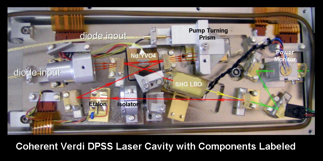
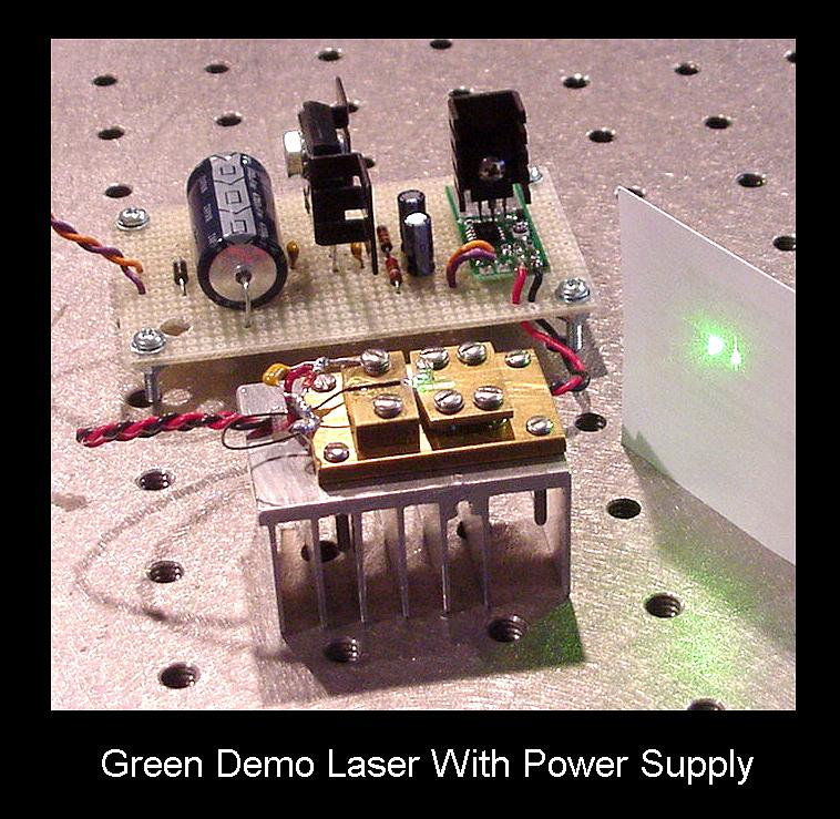
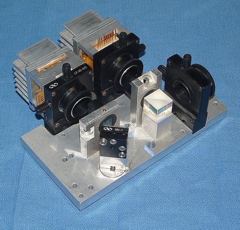
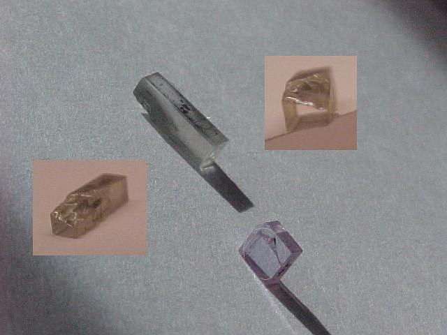
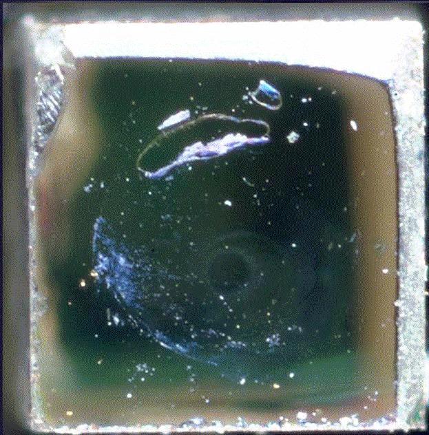