"PuTTy" (https://www.putty.org/) is a basic terminal emulator that should run on almost any Windows PC. However, it is not known if PuTTy has enough options for a formatted display such as required for the Lightwave lasers. It probably does but they would need to be set up individually since there are no pre-defined terminal types. And it is "go to" terminal emulator when accessing remote systems.
Download the appropriate version for your computer. For a Windows PC this is either 32 bit or 64 bit x86. For a real OS, there are many other options. Then set it up as follows. This example is for the typical Coherent Sapphire laser, modify as appropriate:
(Optional) Create a Desktop Shortcut with properties similar to: "C:\Program Files Sam\puTTY\putty.exe" -load "Sapphire" (edited as appropriate).
Test the emulator, adapter, and cable by jumpering pins 2 to 3 at the laser-end of the cable to confirm that characters are echoed when in full duplex mode.
Flashlamp pumping is used when the highest peak power is required in single-shot or low repetition rate (up to 20 Hz or so) operation with and without Q-switching. Each firing of the lamp may also initiate a short burst of lasing pulses, though this is much less common (at least intentionally). Arc lamp pumping is used for CW and high repetition rate quasi-CW or Q-switched operation (typically at kHz rates or higher). There's still a "no laser's land" between a few tens of Hz (limited on the high end by practical electrical considerations) and kHz rates (limited on the low end by the upper state lifetime of the lasing material) where implementation is difficult or impossible. A very few commercial SS lasers have been pumped by tungsten-halogen (incandescent) lamps but not surprisingly, the efficiency was abysmal.
The laser head consists of the flashlamp and YAG rod in a sealed box, the KTP doubling crystal (outside the cavity), servo controlled apertures (variable slits) for X and Y spot size, and a servo controlled attenuator to adjust pulse energy. Note that this attenuator approach is much simpler and more consistent than alternatives using adjustable capacitor voltage or pulse duration control.
The YAG rod is probably about 50 mm long by 3 or 4 mm in diameter, AR coated both ends. The mirrors are glued to the cavity box with the end plates being on split washers to do the alignment. (At first I thought they were non-adjustable, until I attempted to disassemble it!) The servos are the types used for RC models but work fine in this application. :) Optics are glued to precision X-Y adjustable mounts. A fiber optic light pipe cable introduces a targeting beam for viewing the dimensions of the laser spot into the light path via a 45 degree dichroic mirror which is transparent to the laser beam but reflects an adequate portion of the white light beam.
Energy into the flashlamp is about 28 joules (66 uF at 850 V provided by three 200 uF, 330 V photoflash capacitors in series). Triggering is via an SCR and EG&G trigger transformer to an external electrode on the flashlamp. I don't know what the exact maximum output energy is but for this application, but less than a mJ is adequate once the beam is focused to a spot of a few um.
Output energy per pulse is adjusted by rotating the polarization of the green beam with respect to a fixed polarizer, rather than by controlling the energy storage capacitor voltage or actual energy into the flashlamp. A Half WavePlate (HWP) in the green beam is physically rotated by a servo based on the setting of a knob on the front panel.
The optics chain consists of:
The optical path is a loop - the laser shoots down but the two pairs of bounce mirrors turn the beam around twice by 180 degrees. The primary benefit of this arrangement is that the laser head can be about half as long compared to one that was linear. The four folding mirrors do provide additional degrees of freedom to adjust alignment into the microscope objective, but this also makes alignment quite counter-intuitive. And, the slow pulsed laser (maximum rate of 1 pulse per second) doesn't make this any easier! An sensitive averaging thermal or pyroelectric laser power/energy meter with a small probe that can be placed at various locations within the optics chain is essential. Doing it by eye would not be fun!
The controller consists of analog knobs for X and Y aperture and laser power (operating those RC servos, all with digital readout, presumably simply of voltage on the pots), single shot or 1 pulse/second select, and a knob for the targeting light source brightness via a phase control dimmer. Nothing is particularly high tech, but does seem reliable! There are a bunch of trimpots on the hand-wired logic board (!!), probably to adjust the servo limits and maybe set the repetition rate. I don't believe there is any regulation of the laser energy or even flashlamp voltage.
Although the output of the YAG rod is clearly dangerous (it is probably 10 mJ or more) and the final green output may even be hazardous to vision, the system has a Class I rating (unconditionally safe) because everything is fully enclosed under normal operation, it's essentially impossible to place one's eyeball at the output when said eyeball is in its normal location. :) And with the usual delivery via a microscope objective, the beam is very widely diverging at that point and essentially harmless even if reflected from a mirrored surface. There are two sets of head interlocks (which can be bypassed for servicing via jumper plugs): A magnet on the cover and dual reed switches detects cover removal, and a tilt sensor detects if the laser head is not vertical to within 20 or 30 degrees. These are in series with the master interlock connector at the back of the controller and any one of them disables primary power to the high voltage transformer. (The rest of the system continues to function). The firing logic requires a momentary SPDT switch to close one circuit and open the other within a short time. For manual operation, this would generally be a footswitch, but could be from a computer controlled relay, or possibly direct from TTL levels.
The following specifications have been confirmed by Chris Chagaris (pyro@grolen.com) and amended by Dr. Ed Edmondson (EE0035jr@aol.com). However, there could be other variations with slightly different part values so double checking what you have would not be a bad idea! And, of course, if you replace the PFN with one of higher energy, the values for output pulse energy will be greater (unless the flashlamp explodes). (Refer to the Laser Equipment Gallery under "Photos of Hughes Range Finder and Home-Built Pulsed Lasers".)
Where "test data" is listed, it's for a sample of this unit I have which included a test data sheet.
These AN/ Numbers are related to the following equipment. AN/VVS-1 is used on the M60A2 Tank, AN/VVS-2 is used on the M60A3 Tank, and the AN/VVS-3 is used on the M1 Tank. (Note: Only the AN/VVS-1 is definitely a laser rangefinder. The AN/VVS-2 seems to be a night vision system. I do not know about the AN/VVS-3. --- Sam.)
The major contracting firm even made a version designated LAV-105 (Light Assault Vehicle) which was used on a US Marine APC's (Armoured Personel Carrier).
These laser rangefinders were replaced with eye-safe versions using erbium:glass at 1,540 nm and YAG-KTP-OPO at 1,580 nm. This older non-eye-safe version of this assembly is being sold on the Internet by several different surplus companies and individuals on eBay and elsewhere.
Test data: 50 mJ at a PFN voltage of 1,095 VDC.
Test data: 1.4 mW based on 50 mJ pulse energy divided by 35 ns pulse duration.
The top part of the cavity reflector may be taken off by removing the one obvious screw and carefully wiggling the cover loose (if necessary). Take care not to smash the flashlamp in the process. DO NOT TOUCH any of the interior surfaces, especially of the flashlamp! Fingerprint oil may cause it to explode after a few flashes (so they say). The flashlamp does not actually touch any part of the reflector assembly but mounts via its end-caps into a grounded block at the cathode-end and an insulated nylon block at the anode-end The rod is clamped in place in the bottom part of the cavity reflector, possibly cushioned by a layer of indium or other soft heat conductive material.
In normal operation, the motor is spun up on demand just prior to the laser firing. It would be a good idea to implement this feature in any home-built power supply designs to prolong the life of the motor.
Test data: Spinup time at normal operating voltage (?) should be less than 200 ms, 40 ms typical, 70 ms on this unit.
The spec'd maximum voltage is 1,250 VDC and the operating voltage (50 mJ output energy) on the test data was 1,095 VDC.
References:
With the long fluorescence lifetime of ruby - about 3 ms - timing of the Q-switch is not as critical as it is for Nd:YAG with its much shorter fluorescence lifetime (230 us). The Q-switch motor spins at 30,000 rpm or 500 rps for a period of 2 ms. So, with ruby's long upper state lifetime (~3 ms), if the flash duration is resaonably short compared to 2 ms rotation period, there will be a high probability of a decent output energy even if the flashlamp is triggered at random relative to the Q-switch position! Even if the flash duration is as long as 3 ms, half the time, more than 50 percent of the available energy will have been transferred to the rod when the Q-switch is triggered. This is probably the main reason that faulty Q-switch trigger circuits seemed to produce successful results, though I bet the variation in energy due to the timing not always being optimal remained a mystery and was probably attributed to other causes. However, with a proper design, the pulse energy should be quite consistent.
(From: Doug Little (dmlittle@btinternet.com) with some minor edits by Sam.)
The pulse generated by the Q-switch's magnetic pickup looks a little like this:
            /\
        ___/  \    ___
               \  /
                \/
If you build your trigger circuit carefully and make sure you connect the magnetic pickup the right way around (rising or falling edge) you can minimize any unwanted delay between pickup and trigger. You can then of course introduce an artificial and adjustable delay of your own for optimization purposes. A suitable circuit is shown in Q-Switch Trigger Circuit for Hughes MS-60 Ruby Laser and described in the section: Doug's Q-Switch Triggering Circuit for Hughes MS-60 Ruby Laser (DL-ST1).
There are some important things to realize when you try to set up your own timing circuit:
There are two ways around the second problem. One is to run the motor backwards, giving you a whole rotational period of about 2 ms to play with. Being a mechanical motor, this is a lot of time to wait before discharging the lamp without expecting some sort of speed fluctuation. The longer the delay, the less accurate the prism's final (flash) position becomes in terms of motor speed!!! I have strobed the prism with a super-bright LED using a very short on-time of several us and I can say that a 2 ms delay results in a slightly wobbly prism, instead of a preferred rock-solid one. The second solution involves the motor/Q-switch mounting platform. If you loosen the hex bolts you can rotate the whole unit about 5 to 10 degrees in either direction. This affects timing quite a bit and gives you the opportunity to buy back a few 10s of us.
WARNING! Adjusting the Q-switch platform by loosening the hex head clamp screws as a means of adjusting the pickup timing may kill the laser's alignment and require going through the whole horrible process of adjusting the optics with a reference laser and that can take hours. I know because I did it myself. If your laser is already aligned, you may want to think very hard before you do that!
(From: Randy Smith (randysmith@adelphia.net).)
I too have one of these ruby laser units that I am trying to get running. To start off with, there needed to be some sort of timing control unit to synchronize the flashlamp with the spinning mirror. I built such a device using an 87C552 micro, with a 4 digit thumb switch control to allow for an arbitrary offset from TDC (top dead center), entered in degrees. The jury is still out as to the functionality of this unit, but it does look good on a scope and also, when used to drive a small laser diode, it can be used to view the instantaneous position of the mirror. I will find out for sure this coming weekend, when I test it in operation with the laser.
(From: John Grebas (kerravon@bellsouth.net).)
The original PFN produces a 250 us pulse. If the lamp is fired immediately when the magnetic sensor picks up the pulse, approximately 300 us later you will have a beam. You have to have the motor running forward (red motor wire on positive) and the speed set so the period of the magnetic pickup is 1.6 ms.
But I also used a bank of 12, 470 uF, 400 V caps, and a 200 mH inductor, at 979 V to get a 1 ms pulse. I run the motor in reverse with a period of 2.5 ms, I delayed the magnetic pickup pulse by 1.5 ms (between 1.4 ms and 1.5 ms). So with the motor running in reverse with a 2.5 ms period between pulses and a 1 ms pulse from the PFN, and a 1.5 ms delay, you will get your beam (2.5 ms = 1 ms + 1.5 ms). If you follow that you should be OK. So I could run my motor (backward) with a 2 ms period, with my 1 ms pulse I would set the delay to 1 ms (2 ms = 1 ms + 1 ms). Basically your delay + your PFN's pulse time should equal the period of the pulses from the magnetic pickup (controlled by the speed of the motor. Say you have a 700 us pulse from the PFN you could run the motor with a 2 ms period with the 800 us pulse, you would set your delay to 1.2 ms.
I finally got the thing to work but I had to step up the power input to the flash lamp. I simply added a second 150 uf cap in parallel with the other to get a total input of about 216 joules. I charged both up to 1,200 volts. I used the Doug Little's Q-Switch Trigger Circuit for Hughes MS-60 Ruby Laser to synchronize the flash lamp discharge with the Q-switch (See the section: Notes on the Hughes Q-Switch. I ran the motor CCW at 36,000 RPM and adjusted the Q-switch prism to be about 1/8th turn past the pickup when the lamp fires. This seems to give the best results. It blows the ink off a page. Next, I'ms going to see what it will do to metal. :)
I figure that with only the original 150 uF or so cap producing at most 126 joules, at 1,300 volts max, it is probably just barely at the lasing threshold with an optimally timed and aligned Q-switch. The military techs had a device for this unit that tuned the Q-switch without firing the flash lamp. If one had that device then you could probably get it to work with just one cap. Also if it had a real OC instead of just a clear optical medium I think that would help a lot.
(From: Sam.)
Yes, we know that the use of a dielectric OC reduces the lasing threshold significantly. Wes Ellison actually got the laser operating without the Q-switch using an OC from some other ruby laser.
The problem with the resonant optic is that there is no way of knowing if it is any good by inspection or by any easy tests. The location of the reflective wavelength peaks depend on the spacings of the surfaces in a multiple plate etalon. For these low reflectivity surfaces, the response function results in very broad peaks and multiple peaks will fit within the gain bandwidth of ruby so they don't have to be positioned precisely as long as they match. The thickness of the two plates is what determines the peak location for them and they are presumably matched. However, reflections between the plates with a distance determined by the spacer will also affect the overall response. It is not known (though could be calculated) what the exact effect will be. If someone (before you of course!) was curious and disassembled it, even if all the parts were put back together in the correct order, some change in performance is possible, though it's not known how serious this is likely to be. But, even a speck of dust trapped between one of the plates and the spacer could be significant when dealing with wavelengths of light. Given the general difficulty in getting this laser working with the resonant OC at all, replacing it with a dielectric OC with a known reflectance may be worthwhile especially if there is any uncertainty in the resonant OC's condition. And as noted, this could result in a lower threshold as well.
I first tested one of these with a red laser (though not at 694.3 nm, probably a 650 nm diode). The reflectivities of the surfaces are consistent with uncoated glass. I doubt anything has degraded in storage. For it to work as an OC, you don't need much reflectivity, maybe 15 or 20 percent at 694.3 nm. So, presumably, what is required is that two of the dips in the Fabry-Perot resonance of the two plates should (coincide so the attenuation) adds and be within the gain-bandwidth of the ruby crystal (about 0.5 nm). I don't know how they can guarantee that. Perhaps the thicknesses are controllable to the required degree. Or, maybe the thickness of the two plates is not quite the same so that there is a series of dips with slightly different spacing, assuring that one set of them lines up under the ruby gain curve.
Here are some more comprehensive test results using an HP-5501A HeNe laser tube at 632.8 nm. The difference between 632.8 nm and 694.3 nm really should not affect the maximum/minimum reflectivity as an etalon, only the location of the peaks and valleys. This tube has a built-in high quality beam expander and is also quite stable even without being installed in the HP-5501A laser head. The horizontal angle of the OC was adjusted to produce minimum and maximum readings at as close to normal incidence as possible.
The output power of the laser increased slightly as the tube warmed up. So, these sets of measurements were taken a few minutes apart:
  Parameter           Test 1     Test 2     Test 3
-----------------------------------------------------
  Laser power         382 uW     409 uW     414 uW

  Minimum power (T)   221 uW     237 uW     238 uW
   Transmission %      57.8%      57.9%      57.5%
    Reflection %       42.2%      42.1%      42.5%

  Maximum power (T)   362 uW     388 uW     392 uW
    Transmission %     94.8%      94.9%      94.7%
    Reflection %        5.2%       5.1%       5.3%

  Ratio Max/Min T      1.64       1.64       1.65
  Ratio Max/Min R      8.12       8.25       8.02
Note: The reflection (R) values were computed from transmission data since actually measuring the reflected beam at the small angles where the etalon effects are significant would be almost impossible. So, the actual reflected power may be slightly lower due to losses, but probably not by that much for this low-finesse etalon. The maximum reflection of about 42 percent is much more than enough to function as an OC. So, I'm not sure why some people apparently are unable to get this to work. Perhaps they are giving up too easily, assuming it was a lost cause.
"I purchased one of the Hughes rangefinders (two, actually, if I can find the other one...), and have been looking at what might optimize the output. It appears that simmer pulse operation, with 600 V square wave pulses with a duty cycle such that one pumps for the length of a rotational period without killing the tube would do the trick. IGBTs would do the switching - the question is how to trigger the tube without a serial transformer in the existing cavity. The best idea I have would be to use an insulated wire externally as the trigger - has anyone tried this and made it work?"
(From: Chris Chagaris (pyro@grolen.com).)
How exactly do you intend to "optimize the output"? I get the impression that you wish to optimize repetition rate by utilizing a pseudo-simmer mode circuit. You must realize that this laser was designed to operate at a low repetition rate and must do so for a number of reasons. The original flashlamp contained in this laser is an EG&G, FX-103C-3 which is the predecessor of their FXQ-1302-3. With the design of this cavity employing only convection cooling of this original lamp, the maximum average power is rated at only 20 watts. At an input energy to the lamp of let's say 100 joules (somewhat above minimum for laser operation) your pulse repetition rate would be limited to one pulse every five seconds. With such a slow repetition rate I cannot see the justification for employing a simmer mode of operation. Since there are no active means of cooling the ruby rod, this could also present a problem, as ruby does not dissipate heat very well and the likelihood of damage from over-temperature is great if this system were to be operated much above its design limitations. With the configuration of this particular laser cavity (semi ellipse) the use of an external trigger wire for successful firing would be highly unlikely. The flashlamp is in intimate contact with the grounded aluminum base of this reflector to aid in the cooling of the lamp. A wire of any kind would interfere with this contact and of course would serve no purpose as the current would just flow to ground. A wire with enough insulation to protect against the very high voltage pulse (10 kV or more) would be very impractical.
(From: Sam.)
I agree with Chris 100% that boosting the repetition rate isn't really viable. As far as triggering, an alternative to series triggering is parallel triggering which can easily be extended to multiple trigger sources. See the section: Basic Structure and Characteristics of SS Laser Power Supplies.
(From: Chris.)
In more detail, there are two points to consider in answering this question:
P(avg) = E x f
Where:
The flashlamps that one may find in the MS-60 rangefinder ruby lasers are either the original EG&G lamp, FX-103C-3 or the replacement EG&G flashlamp, FXQ-1302-3. Since this ruby laser's cavity is not actively cooled (merely convection cooled) the maximum average power rating for these lamps are 20 watts and 150 watts respectively. Consider an input of 100 joules to this first lamp. This would limit repetition rate to one pulse every five seconds. This same input to the replacement lamp rated at 150 watts would give you a safe maximum pulse rate of 1.5 pulses per second. Of course an increase in pump energy to the lamp would decrease the maximum safe repetition rate.
Ruby was never meant to be pulsed at a great repetition rate. Another problem that one would face at high repetition rates is the overheating of the ruby rod, which does not dissipate heat too well (unlike YAG). This can permanently damage the ruby crystal.
(Note that there is a unit showing up on eBay with labels showing "MILES US ARMY" and "LASER TRANSMITTER ASSY M16A1" that looks like it might contain an SSY1 head. However, this device is used for battle simulations or war games and only has a pulsed 904 nm laser diode.)
The SSY1 laser head used to be available from Meredith along with a matched pulse forming network (see the section: Pulse Forming Network 1. (Meredith had also been auctioning these and other items on eBay.) SSY1s frequently show up on eBay from various sellers. The going price is in the $100 to $200 range for the laser head. New SSY1s and parts may also be available from Anderson Lasers, Inc. and elsewhere. I constructed a capacitor charger and external trigger circuit. See the section: Sam's AC Line Power Supply for SSY1 (SG-SP1). An alternative design which runs from low voltage DC is described in the section: Sam's Inverter Power Supply for SSY1 (SG-SI1).
For initial testing, figuring it would be real effort to get it lasing, I used my trusty IR remote control tester for detecting the beam. Big mistake. :( The first shot sent the photodiode off to photodiode heaven (or wherever faithful photodiodes go when they die). Its output just stayed on! I should have used the IR detector card available from Radio Shack (and elsewhere (though that would probably have suffered as well). (For reference, the output is from the end with the red wire. The ends look identical.)
OK, so go to plan B. :)
I placed a piece of black coated paper in front of the laser and fired off a few shots. No effect except for a bright blotch of white light from the flashlamp. (Maybe I didn't examine it closely enough.)
Next, I tried a small lens approximately focused on a piece of black coated paper. To make sure any effect wasn't just due to spill from the flashlamp, these were positioned about a foot from the laser head. Immediate gratification! The moderately focused output beam easily obliterated the black coating on the paper. This was accompanied by a very nice 'snapping' sound and white or yellow incandescent plume when hitting the black coating, and a more muted sound after the black stuff had vaporized. When carefully focused, it will make nice tiny holes in aluminum foil (the incandescent plume is green-blue in this case) and other thin materials, and mini-craters on thicker objects. I've heard of people driving this laser with much higher energies to blasting holes in razor blades (see below). However, it is all too easy to blow up the laser components when doing this - the flashlamp and Q-switch are most susceptible to damage or destruction.
I don't have any way of actually measuring the energy of the beam but let's just say it is definitely not something to be taken casually, as far as eye safety is concerned! My wild off-the-top-of-the-head guestimate would be at least 10 mJ, probably 20 or 30 mJ, though it may be as high as 50 to 100 mJ. Hopefully, someone will eventually measure the output pulse energy! The Nd:YAG rod is probably capable of much greater energies but that flashlamp doesn't look all that sturdy so I'ms not about to push my luck, at least not yet. :)
The lasing threshold is about 7.5 J - less than the energy of the electronic flash in a typical pocket camera! This low value is no doubt due to both the cavity and optics design - and the optimal pulse length from the PFN. Thus, using one of those cheap flash units (or just its power supply) directly probably wouldn't work at all as the duration of the flash pulse would be way too long with insufficient peak intensity. (The unit described in the section: Micro Laser Rangefinder Using Disposable Flash Pumped Nd:YAG and OPO is based on a much smaller Nd:YAG rod - about 1/8th the volume.)
Here are the specifications, as best I can determine:
The white flashlamp trigger lead is connected to a fine wire that runs the length of the inside of the bore where the flashlamp lives.
The cavity assembly may be detached from the outer casting by removing 4 screws providing access to the inner surfaces of the HR and OC, and the rod ends for cleaning. The flashlamp may then be removed by unscrewing a nylon fastener at the anode/OC-end and carefully straightening the cathode lead. CAUTION: Avoid touching the flashlamp envelope. If you do so by accident, clean it thoroughly to remove all traces of skin oils.
The maximum energy input using this power supply is 15 J (36 uF capacitor charged to 900 V. Nearly 100 percent of the energy in the capacitor is transferred to the flashlamp. An energy of 15 J may not sound like much but it is more than adequate (actually twice the threshold) for pumping the 50 mm rod with the optimal 100 us pulse duration and well designed cavity
Note: The dimensions are from my memory or lack thereof - I haven't measured them since getting SSY1 to lase, corrections welcome.
WARNING: Despite its small size, this is a Class IV laser. While SSY1 probably won't set anything on fire unless you fire it at an explosive or have a natural gas leak, this laser is quite capable of doing serious damage to vision. Treat it with respect! Cover the HR mirror aperture (I used black electrical tape) since there may be some leakage from there which is invisible and enclose the output beam path so that backscatter can't hit anything of importance (like your eyes).
I've now tested 3 of these babies - 2 that appear to be in original condition and another with the Q-switch removed and the AR coating gone from one end of the rod. (I've also used the mirrors from an SSY1 to construct the resonator for another YAG cavity, see the section: Mini YAG Laser using SSY1 Optics and SG-SP1.) The two intact units produce about the same output energy. The other one lases but probably at slightly lower energy. It still smokes black tape (possibly better than the other ones) but won't penetrate aluminum foil. The sound it makes when focused on a target is also softer. However, I don't know to what extent these differences are due to the lack of a Q-switch versus the missing AR coating It's probably a combination of both but the reduced effect on thermally conductive aluminum foil and softer sound would be consistent with the longer, lower peak power pulse produced without a Q-switch. Perhaps at some point in the future, I will swap rods with an original SSY1 to separate out the effects of the missing Q-switch and AR coating.
CAUTION: Although the capacitor in the PFN that comes with SSY1 is rated for around 35 uF at 900 VDC, running at this energy may destroy the Q-switch dye cell and possibly the AR coating on the YAG rod adjacent to it after not too many shots. Some samples may survive almost indefinitely but others could succumb in less than 100 shots. I would recommend limiting the voltage for repetitive use to 700 or at most 750 VDC.
I am trying to build a laser rangefinder using this laser.
(From: Ivan (sinebar@bellsouth.net).)
I got my small YAG laser working using the PFN from Meradith Instruments and a power supply based on the SG-SP1 schematic. Even without a lens it will burn a spot on a black target.
(From: Rick (rick@skyko.com).)
I got bored this afternoon and figured I would dig out the SSY1 I bought a few months ago on ebay from Meredith. If that is not the easiest laser to get lasing, I don't know what is. I think it is easier than modifying a green pointer! :-)
I started with two plain old 330 uF, 400 V electrolytic caps in series from my junk box (I have some 1,500 uF 450 Cornell Dublier electrolytics, but I didn't want to take out the Q-switch yet). I then dug out a smallish 12 VDC-powered hene supply (for like a 1 to 2 mW tube and wired that up to the caps through ten 100K 1/2 watt resistors wired in series (for 1M at 5 W). I found a dented old auto ignition coil transformer deep in my junk boxes and I wired up a 4:1 divider using 1M 1/2 resistors off the caps to charge a small 2.2 uF 250 V capacitor. To fire the laser, I turn on the HeNe laser power supply, watch the voltage across the main caps charge (about 20 V per second or so) and then when it is at the desired voltage, I short the 2.2 uF cap across the input terminals of the auto ignition transformer, whose coil is hooked up to the trigger wire of the SSY1. I then took a note from Sam's experience and wound about 55 turns of 14 gauge plain old solid copper wire with thin plastic insulation around an used up plastic speaker wire container bobbin. I measure the inductance of the completed coil with my LC meter and found it to be 199.5 uH. Not bad! Overall though I would say it is the crudest SSY1 power supply yet! :-)
For the very first shot I was not absolutely sure which end was the output, lol, so I put a black electrical tape target about 2 inches from each end. I let the main caps get to 450 V total and then shorted the 2.2 uF cap to the transformer. A nice satisfying flash! and a perfect 3-4 mm white spot on the electrical tape on the end with the red wire (ah, the output end, heh heh).
I then found a 1.5" FL lens and proceeded to de-anodize some aluminum. The thing is loud when it is focused. I am actually adjusting the focal length as I type (while waiting for the cool down of the SSY1 lamp (what is the duty cycle on these things anyway? (Figure about 10 W average power into the lamp. --- Sam ) I am giving it about 3 to 5 minutes between pulses). I think I may be able to make some small craters in the black anodized aluminum, but maybe not until I swap out the series 330 uF caps for the series or paralleled 1,500 uF ones (after removing the Q-switch).
Not a bad little laser for $125. It really deserves a better supply though. :-)
(A day passes.)
I just fired a shot from my SSY1 with 165 uF caps (two 330 uF caps in series) charged to 550 V (so about 25 joules) into a Molectron J25LP-0686 sensor head with a responsivity of 5.0 V/joule at 1064 nm. I measured a 620 mV pulse on my oscilloscope.
This would mean the output power from the SSY1 at 25 joules to the flashlamp is 124 mJ.
Is that even remotely possible?
(From: Sam.)
Might be a bit high, but not out of the question.
(From: Rick.)
It does punch a hole through aluminum foil at this power level, and also it pits a stainless steel razor blade (but does not punch through).
It also left a 4 mm mark on the carbon looking sensor head... whoops. :-(
While making some more power measurements from my SSY1, I heard an increasing snapping sound as I went up in pump joules. Since I have the power sensor head well past the focal point of a positive lens (normally I would hear this snapping sound when I focused the spot on a piece of electrical tape or aluminum foil) I was wondering where it was coming from. I then covered the SSY1 with a piece of cardboard to mask the flashlamp light spillage and fired it up at 165 uF, 700 V (40 J). I saw a bright pinpoint flash of light at 1.5 inches from the lens in mid air! Very very cool (first time I have seen this phenomenon, though I have heard of it). I guess this gives another data point to the output power level... Air sparks at 200 to 400 mJ? :)
I am going to try and capture this on video and stick it on my Web site.
(From: Sam.)
Use a shorter focal length lens and the light show will be even more spectacular and/or occur at lower energy.
(From: Mike Poulton (mpoulton@mtptech.com).)
You can push them really hard. I ran about 1 kW average input power for 5 seconds at a time, letting it cool about two minutes between bursts. I had a small fan pointed at it, but no real forced air. It didn't like this, but I did it quite a few times and it still works fine. The yellowish plastic around the cavity is discolored brown from the heat - it was probably close to 400 °F and it didn't fail.
(From: Sam.)
On another note, the laser described below is the modern version of SSY1 which is similar, perhaps even a bit smaller:
(From: Erbium1535 (erbium1535@aol.com).)
The South Carolina State Museum in Columbia uses a Nd:YAG laser to pop a balloon inside a balloon in their Townes exhibit. (C.H. Townes was born in Greenville, South Carolina.) The laser, manufactured by Kigre, Inc. in Hilton Head, SC is a Q-switched MK-367 unit and is described on the Kigre MK-367 Nd:YAG Laser System Page. The actual laser is approximately 0.6 x 0.8" x 4" in size and emits a 17 mJ pulse pulse with s duration of less than 4 ns. They also offer a frequency doubled green version. The MK-367 was originally developed for the ophthalmic surgical market, specifically as a photo disrupter for posterior capsulotomy. The power supply is approximately 4" x 4" x 1.5" and operates from 12 VDC.
The laser is somewhat unique in that it is permanently aligned, utilizes a ceramic exoskeleton for stability, and a positive branch confocal resonator design for high beam brightness. Kigre has sold more than a thousand of these miniature lasers for various applications including medical, industrial, rangefinding, and pyrotechnic ignition. The MK product line has been around for more than 15 years, so these lasers sometimes find their way to the used laser discounters. New ones are still available and cost about $3,600. If you do come across one of these, be very careful as it is a very powerful Class IV laser! (Yes, but the SSY1 is potentially an even more powerful Class IV laser! --- Sam.)
I have some news about what I have done with the SSY1. The Q-switch is retained. I used two lab power supplies (ye olde tube-type monsters) to charge the stock PFN to 800 VDC, and used the trigger pulse from a small photoflash unit to fire the flashlamp. The discharge resistor made a convenient current limiter for the charging. I first tried it with the photoflash unit to charge PFN1 but my SSY1 would not fire at the photoflash-supplied 400 V on the lamp.
I had no carbon paper so I took a small white cardboard box and a black 'Sharpie' pen and painted a square made of 5 layers of ink, allowing the ink to dry between layers. I was gratified to see the laser work the first time and ablate the ink nicely. The ink method may be better than carbon paper for some purposes. I took pictures and videos which I hope will be interesting. The Kodak P850 camera is ideal since it does 30 fps video at 640x480 resolution. It also allows one to edit the video in-camera as well as extract individual frames to create images. OK, this is not a Kodak Ad, just saying what gave me good and easy results without having to buy editing software. One thing that surfaced is the apparent TEM02 mode of the laser. This appeared in the ablation marks in the ink. They were very hard to see by eye but the camera picked them up. The mode marks seemed to remain the same from pulse to pulse, so I believe it is genuine. I hope you enjoy the pictures and videos. Some are quite large, but I made also an animated GIF where I increased the brightness and reduced the speed and you can really see the smoke.
Here is the page: Patrick's SSY1 Laser Page.
(From: Sam.)
Well, I have to say, that's the BIGGEST SSY1 capacitor charging power supply I've ever seen. Heck, a 6 VDC input HeNe laser power supply can easily charge PFN1. :)
As far as the TEM02 mode pattern. I think that's just the tip of the iceberg. The diameter of the SSY1 rod with the plane-plane resonator is much too large to assure a TEM00 mode, probably by at least a factor of 2. So the actual mode pattern may be much more complex than what is appearing in the smoked ink.
(From: Shawn West (west007@libcom.com).)
I've taken a different approach than the others and am pumping it with a long pulse, about 2.5 ms. With my long pulse I have put a 0.020 inch diameter hole in a 0.004 inch thick razor blade. I've punched holes through aluminum foil of different thicknesses too. I've back calculated the energy required to punch the holes in the razor blade and the two aluminum foil experiments. The calculations show that it would have taken 1.7 to 1.8 joules to melt and vaporize the metal in each case (if I did my calculations right). When I hit the razor blade with 800 volts on the capacitor (360 joules) I was able to punch a 0.024 inch diameter hole in the 0.004 inch thick blade. My calculations, which again could be wrong, show that it would have taken about 2.5 joules to do this. These calculations do not include the amount of reflected energy or the energy conducted away from the material. I have also sparked the air using a short focal length (about 1.5 cm) lens. I'ms using a 1,120 uf capacitor with approximately a 0.15 ohm ESR.
My inductor is 820 uH with a resistance of about 0.15 ohms. It is from Parts Express (part #266-760, about $23). The inductor is wound with an effective 12 gauge copper foil and has an air core. I'ms using a piezo-electric igniter from a gas grill to flash the tube.
I have also used a 270 uF capacitor and a 80 uH inductor (ESR of 8 or 9 milliohms). However, the longer pulse PFN put out more energy (more destruction to the target) than the short PFN when the caps were charged with the same energy. This could have been due to the ESR differences of the two capacitors or the higher current density with the shorter pulse PFN exciting the shorter wavelengths of the xenon (i.e. not exciting the 800 nm hues as well to mate with the Nd absorption). I'ms trying to keep the current density in the flashlamp below 4,000 A/cm2 to favor the 800 nm absorption band of the Nd:YAG crystal. I also wanted to pump out a lot of energy. This forced me into a long pump pulse.
I spoke to Jim McMann (sp?) from Perkin Elmer (EG&G) about the flashlamp in mid-December, 1999. His phone number is 1-800-950-3441. At that time, he thought the flashlamp was an FXQG-264-1.4. From what I have found out since then, there are two EG&G flashlamps that could have been used for the SSY1. The first is the FXQG-264-1.4. This flashlamp is made from titanium doped quartz that cuts off UV wavelengths below about 225 nm. The second is the FXQSL-559-1.4. This flashlamp is made from cerium doped quartz that cuts off UV wavelengths below about 320 nm. I don't know which one was originally used.
Both of these have a 1.4 or 1.5 inch arc length, and are probably xenon filled to 500 Torr (though I have not been able to verify the fill pressure). The ID was 3 mm and the OD was 5 mm. If you calculate Ko with a 1.4 inch arc length, you get:
               1.28 * (1.4 * 25.4)        500
         Ko = --------------------- * (---------)0.2 = 15.5
                        3                 450
Using a 1.5 inch arc length results in a Ko of 16.6 which is what I measured
it to be.
For the more conservative arc length of 1.4 inches with a 3 mm bore, the explosion energy for the flashlamp = time.5 * 90 * arc length in inches * bore in mm = 378 * time.5. (Time is in milliseconds.)
I designed this to run from 300 volts (50 joules) to 800 volts (360 joules). My damping factor (alpha) ranged from 1.03 at 300 volts to 0.8 at 500 volts to 0.63 at 800 volts. I think at about 560 volts the current density in the flashlamp was about 4,000 A/cm2. The explosion energy with a 2.5 ms pulse is about 590 joules and at 800 volts I was running at about 60% of the explosion energy. I normally run at about 560 volts where alpha = 0.76, at 30% of the explosion energy (about 177 joules), and the current density is about 4,000 A/cm2 in the flashtube (the approximate maximum current density for which the 800 nm line is strongly excited). When I was hitting the razor blade and the aluminum foil the capacitor was charged to 700 volts (274 joules - about 46% of the explosion energy). The maximum pulse rate is about once every 45 seconds. Right now my charger is running from 120 Vac but I plan to make this portable and run from 12 volts with a pulse rate capability of about once every 30 to 40 seconds.
I have not removed the Q-switch to see the effect yet.
(From: Sam.)
Well, that's certainly impressive!
I assume that with the Q-switch, you are actually getting a series of short pulses of a few dozen mJ each. My quick off the top of my head calculation for output energy using the Q-switch would be 25 to 50 times 20 or 30 mJ which is in the .5 to 1.5 J range so your calculations of output energy may not be far off. This laser would probably also do nicely with an arc lamp if you could cool it somehow. :)
(From: Shawn.)
My scope is getting calibrated now, but when I get it back I'll check the reflected light to see I am getting a bunch of pulses or a long continuous pulse with a steep front end (maybe even a spike on the front end of the pulse). Does this Q-switch have a self terminating bleaching effect independent of incident power or does it remain bleached as long as the power is above a certain threshold?
(From: Sam.)
I don't know for sure but assume that it returns to its non-bleached state immediately after the laser pulse and until the spontaneous emission (not the incident flashlamp power) exceeds the threshold again. Not knowing the exact composition of the dye used here, I can't say what the exact time is. For the rangefinder, the likely objective would be one intense pulse for each firing of the flashlamp so there would be no need to select one that recovered quickly but they do exist.
(From: Greatest Prime (FishyBill@mediaone.net).)
The nickel complex BDN in toluene has a recovery time of about 1 ns. (Actually, you can make it in a number of ways. One is to dissolve BDN in methyl methacrylate and polymerize it. You have to watch out the active catalysts do not destroy the dye.) This allows for multiple pulsing. Other dyes and solvents tend to shorten the recovery time. That is what makes mode locking possible at a pulse repetition rates of more than 100 MHz. However, repetitive operation of dye Q-switched lasers is more complicated than merely considering recovery time of the dye. There usually are long term thermal effects of considerable importance.
(From: Sam.)
It might be possible to test the SSY1 laser for multiple pulsed operation by firing the flashlamp with a longer than normal pulse. Once the first Q-switched output pulse depletes the upper energy state, the Q-switch should revert to its non-bleached condition. If the flashlamp is still on, the cycle should repeat. Doubling the flashlamp pulse duration from 100 to 200 ns while maintaining approximately the same flashlamp light intensity should be enough and this can probably be done safely (for the flashlamp and dye cell at least for a few shots to perform the test) by doubling the values of the PFN capacitor and inductor. I've heard of rangefinder lasers similar to the SSY1 failing in a way that results in multiple output pulses - this may be a way to experiment with this mode! Diode pumped solid state lasers take advantage of this effect to generate a series of very short pulses with very consistent energy between pulses and a rate determine by the pump input.
One way to determine the pulse shape or pattern would be to fire the focused laser beam at a rotating disk with a piece of black paper or carbon paper glued to its front surface. The shape of the burn mark or pattern of spots should reveal whether it is lasing CW for the duration of the input pulse or pulsing at a regular rate as would be expected if the Q-switch were active the entire time. A 75 mm diameter disk rotating at 3,600 rpm would result in a linear velocity of about 1.4 mm/100 us for this laser oscilloscope. :)
(From: Shawn.)
I noticed that my divergence is significantly greater with the long pulse (2.5 ms) versus the short pulse (approximately 400 us). Do you have any thoughts on why this could be happening? How much more energy do you think I could get out if I removed the Q-switch?
When I was using the short pulse PFN I could discolor a black piece of cardboard about 2.5 feet away with the spot size only growing slightly (perhaps a few mm in diameter). However, with the long pulse PFN, I placed a piece of black cardboard about 3 inches from the output coupler (and hit it) and then moved it back 4 inches (about 7 inches from the output coupler) and the diameter grew by about 2 mm. At about 1 foot from the output coupler I can't discolor the black cardboard with the long pulse PFN.
(From: Sam.)
That's interesting and could indicate that the dye does remain bleached after the initial pulse. Or, the dye bleaches from the center out which would restrict the area of lasing when Q-switched.
(From: Shawn.)
Are you thinking that if the dye bleaches from the center out in combination with the applied pulse duration, then the Q-switch will effectively clip the higher order modes letting only TEM00 to oscillate. However, with a long pulse, the dye possibly remains bleached over the whole rod diameter which permits the higher order modes to oscillate creating the high divergence. Maybe I should pull the Q-switch and insert an aperture into the cavity to clip the higher order modes?
(From: Sam.)
As far as total energy, if the Q-switch is not participating after the initial pulse, than it won't make much difference. However, if the dye bleaches and recovers quickly, then perhaps it could be significant.
(From: Shawn.)
I use a cheap 660nm laser pointer to bore sight the laser. When I get the laser pointer lined up I can see the "orbit" reflections that seem to surround the fundamental spot. However I thought with a plano-plano cavity the reflected spots tend to follow a line from the fundamental or follow a slight curve (i.e., not surround the fundamental spot). Could this cavity be a near hemispherical or a plano-plano cavity? If this is a near hemispherical cavity could that explain why the center of the q-switch would bleach first?
(From: Sam.)
I thought it was a plano-plano cavity but didn't check carefully. Just look at the reflections from the optics of something distant and see if they look flat. :)
Shining a laser pointer into it you also have reflections from the rod ends and the Q-switch to confuse things. I'll have to check...
I just went and used a HeNe laser reflected off the mirrors with a piece of paper to block the reflections from the rod ends and Q-switch (so they wouldn't confuse things). The mirrors appear to be planar as far as I can tell but this still isn't conclusive since I was just kind of holding the thing steady and trying to view the reflected spots.
It does look as if the rod ends and/or Q-switch is ground on a slight angle because without the paper, there is a distinct far off-axis spot.
(From: Shawn.)
I noticed that far off axis spot too when I'ms bore sighting it with the laser pointer. Do you think it would be worth it to put an aperture in the cavity and how big of an aperture do you think would be good to use? What is confusing me is that the output of the side of the rod closest to the flashlamp seems to put out more energy and I am trying to envision the optimal location for the aperture (i.e., should the aperture be placed off centerline toward the flashlamp side).
(From: Sam.)
The fact that you get more energy off-center suggests (at least to me) that the cavity is indeed planar. A cavity with curved mirrors would tend to homogenize the distribution I would think.
What are you hoping to accomplish with an aperture? Obtain a TEM00 beam? That may not be possible from such a short cavity. There's a magic number for a given cavity configuration to determine if a TEM00 beam will be produced (sorry, I don't have the equation or the value for this laser) but I bet it would require a rather narrow beam.
(From: Shawn.)
I was just hoping/dreaming to be able to project the unmanipulated beam further. I think you are right again about the planar cavity. A near hemispherical cavity should have more energy in the center.
(From: Sam.)
Well, you can still expand/collimate it and that will help but if you were after HeNe-like beam quality, not likely. :)
(From: Shawn.)
I fixed my divergence problem. I remember when I got the laser, I illuminated the bore and noticed a slight star-burst pattern that seem to be coming from the Q-switch. Yesterday, I noticed the star-burst getting more pronounced. I guess my higher energy pulse must have aggravated the existing imperfection. So, I removed the Q-switch. My divergence problem has gone away. I'ms assuming that the imperfection in the Q-switch was dampening the oscillations in the center of the laser rod. The beam now grows about 0.1 to 0.15 inches in diameter over a 3 foot distance.
Before, when I charged my capacitor up to 700 volts (about 275 joules) I could only put about a 0.020 inch diameter hole in a 0.004 inch thick razor blade. Now, without the Q-switch I can put a 0.033 inch diameter hole through the same razor blade. If you just ratio the changes in volume the output energy has increased by over 2.5 times.
(From: Sam.)
Yes, I've heard that the dye based passive Q-switch is one of the items that fails most often (the other being the flashlamp). So, it may have been slightly bad to begin with but your super power pulses might have really done it in!
For those who haven't yet begun to abuse SSY1, it is probably best to remove the Q-switch dye cell before attempting to run at much higher energy input than the 15 J max of PFN1. To do this, detach the rod/flashlamp assembly from the resonator frame (make a note of the direction in which it is installed). At one end you can see an AR coated end of the YAG rod (I think there is a screw at that end which holds the rod in place). At the other end is the Q-switch dye cell (slightly larger diameter than the rod) which is held in secured with some tan or brown adhesive which has to be removed to free it. There is a tiny fill hole where some adhesive was forced in on the side - using a drill bit in your hand to remove what's in there may also be needed. Take care to avoid scratching or breaking the dye cell - you may want to replace it at some point in the future (and that dye cell originally cost something like $200!).
Without the Q-switch, the output will not be as short a pulse but may actually result in more total energy (though less peak power).
(Several months pass.)
I have now built everything into a portable self contained unit (including the laser pointer target designator) that could operate from a 12 VDC source. A pushbutton must be held in to charge the caps but there is an overvoltage cutoff to prevent accidental overcharging. There is an LCD readout for capacitor voltage. Of course, the most important part of this rig is my pair of 1,064 nm laser safety goggles!
I've fired well over 2,000 shots with my SSY1 setup and there appears to be no decrease in output power (based on the diameter of hole through a razor blade). The Q-switch has long since died and was removed about 2,000 shots ago. :) My max pulse rate is about 1 shot every 45 seconds. EG&G says that I am driving the flashlamp properly. I bought a couple extra flashlamps just in case.
I've made a sort of hodgepodge laser power meter. I sliced a piece of carbon from a carbon zinc battery anode. The slice is 0.239" diameter (6.071 mm) by 0.065" thick (1.651 mm). I epoxied a thin piece of plastic to the back of the carbon disk to act as an electrical insulator for a Fluke k-thermocouple junction. The thermocouple junction was epoxied perpendicular to the flat surface of the disk. I used an 805 nm laser diode to "calibrate" the disk. The laser diode is calibrated. I set the laser diode to put out 1 watt. I put the carbon disk in front of the laser diode aperture and turned on the laser for different durations as measured by an oscilloscope. I took several measurements while measuring the delta T and time duration for each exposure to the laser diode. Approximately 2 minutes elapsed between each measurement. My data is shown below:
    Test   Tinitial   Tfinal    Delta T   Pulse Duration   MC calculated
      #    (Deg C)    (Deg C)   (Deg C)     (seconds)      (Joules / C)
   ----------------------------------------------------------------------
      1      23.8       30.0       6.2         1.56            0.252
      2      24.1       31.2       7.1         1.67            0.235
      3      24.2       27.8       3.6         0.92            0.256
      4      23.8       28.2       4.4         1.11            0.252
      5      23.7       26.1       2.4         0.58            0.242
      6      23.5       34.1      10.6         2.50            0.236
Energy into the sensor in joules = time duration in seconds since the power
input is 1 W. The average MC comes out to be 0.246 J per Deg C.
It took about 10 seconds for the temperature to stabilize. I guess that the thermocouple wires were not bleeding away the heat too fast.
I charged up the capacitor for the SSY1 to different voltages and fired it into the sensor which was about 1 foot away. I have a laser pointer with a cross hair diffractive lens that bore sights the laser and is aligned to perhaps 1 to 2 mm. The following are the test results:
  Vcap   Tinitial  Tfinal Delta T Calc Eout    Flashlamp Energy   Efficiency
 (Volts)  (Deg C) (Deg C) (Deg C) (Joules)  (Joules, from Pspice)     (%)
-----------------------------------------------------------------------------
   350     24.4     27.0    2.6     0.64           57.1               1.1
   400     23.7     28.3    4.6     1.13           73.6               1.5
   450     23.9     29.9    6.0     1.48*          91.9               1.6
   500     23.9     31.7    7.8     1.92*          112.0              1.7
   500     24.0     31.3    7.3     1.80*          112.0              1.6
   550     24.0     32.2    8.2     2.02*          133.8              1.5
   600     23.8     33.6    9.8     2.41*          157.3              1.5
* Smoke came from the sensor during these measurements!
The flashlamp energy was calculated by the Pspice simulation. The following are some of the things that were not considered in the measurements:
(From: Sam.)
Cut, file, or grind one of your carbon rods to create some slices length-wise. Sand them smooth and butt the long edges together to form a larger surface area. Yes, I know this will be messy!
You're getting me interested in trying this stunt. I have a pair of 1,800 uF, 450 V computer grade electrolytic caps. Yes, I know, not laser caps, but at with relatively discharge pulse, might survive. With the caps in series, at 800 V, they would provide about 288 J; at 900 V, about 360 J. Or, better yet, I should run them in parallel which would be slightly less efficient but would eliminate any issues of voltage balancing, reduce the stress on the flashlamp, and the air-core inductor would only need to be about 200 uH. I have plenty of thick wire to wind it.
I would remove the Q-switch before the first shot so that it would live to pulse another day. :) I also have some other mirrors with cosmetic defects which I might substitute as well. The same capacitor charger I used originally with SSY1 would work fine here though I might have to beef up the current limiting resistor's wattage a bit. :)
As I mentioned, the air core inductor I used was from parts express. It was about 2.5 inches in diameter and about 2 inches long. It was wound with copper foil 2 inches wide and used insulation between each layer. However, here is a formula for the inductance of a coil whose length is greater than 0.4 times its diameter:
                                        d2 * t2
          L (Inductance in uH) = ---------------------
                                  (18 * d) + (40 * b)
Where:
(From: Sam.)
Nah, that's cheating. :) I found a 3 inch diameter form during a walk in the park - from a Hallmark(tm) party ribbon or something - perfect. Extrapolating from the tables above, a 200 uH inductor would require about 50 turns. I actually wound 55 turns in 5 layers using #14 insulated solid building wire. This isn't exactly magnet wire but the insulation is still rather thin so it packs nicely. The 55 turns should yield a bit more inductance - perhaps 250 uH - resulting in a slightly longer pulse. So much the better - it will be easier on the flashlamp.
I located the pair of 1,800 uF, 450 V caps and confirmed that their ESR is still unmeasurable (0.0 ohms) but I will probably need to reform them since they are quite old. I even have a preliminary power supply design. See the section: Sam's High Energy AC Line Power Supply for SSY1 (SG-SP3) and stay tuned for exciting developments.
I successfully fired the SSY1 with a cap bank at 64 uF at 985 V. It made a very clean hole through a razor blade in one pulse with the aid of a focusing lens. I understand that this is running the tube pretty hard at input of around 31 J. I could not find out how long the tube would last under such stress.
(From: Sam.)
That's very impressive since the energy input is significantly lower than that discussed above! I do assume you removed the Q-switch dye cell as it probably wouldn't last long under this abuse. As far as lamp life, it is running 3X or 4X of the energy normally used in the rangefinder application. So, life will be reduced but it would be necessary to calculate the expected life based on the lamp's specifications.
I put together a OrCad (formerly Microsim) Pspice simulation that accurately models the flashtube characteristics (with a given Ko) that agrees with measured results.
Based on the simulation, the amount of energy that actually makes it to the flashlamp terminals is about 75% of the capacitor stored energy for my PFN setup. So for my previous % of explosion energy numbers you can multiply by 0.75 to get the real % explosion values. So, for worst case (800 volt = 360 joules stored on the capacitor) only about 270 joules make it to the flashlamp which gives a % explosion energy of 270 / 590 = 45% rather than the theoretical maximum of 60% as previously stated.
The Pspice files (ASCII text) for the flashtube follow. You can change Rctrl from 1u to put the reverse diodes in the circuit or a 1M resistor to take the diodes out to see if you would be getting any negative ringing current. Resr is the ESR for the capacitor and Rind is the resistance of the inductor. You can set the capacitance, inductance, Ko, and the initial capacitor's voltage in the PARAMETERS box. You can use Rsense to display the flashtube current. Vtube is the voltage across the flashtube. The energy line integrates the tube voltage x tube current to arrive at the energy that makes it to the flashtube to gauge the efficiency of your circuit. For the energy line 1 volt equals 1 joule. The key for proper simulation is to know the proper C, L, Rind, and especially Resr.
The peak power of SSY1 is something like 16 mJ/4 ns which is 4 MW. I'd expect order of 1 mJ of green without any optics - just put the KTP in the beam and adjust its orientation for maximum green output. The green beam will be almost coaxial with the IR beam with a walk-off of only about 4.5 mR. One problem though is that the beam from SSY-1 is not polarized so you will lose some efficiency there. I don't know how much. But if the KTP is aligned properly, there should definitely be some green photons produced. First try this simple approach to the determine if the green pulse energy and consistancy are acceptable. There is no space inside the SSY1 resonator for a Brewster plate with the Q-switch in place so one of the mirrors would have to be re-mounted externally.
CAUTION: I recommend using an aperture to make sure the IR beam hits only the clear central part of the KTP as at high enough power/energy, it could conceivably damage or destroy the KTP if it hits something that absorbs significantly. (However, as I found out, this is probably critial with SSY1 driven from PFN1. See below.)
Adding optics to concentrate the 1,064 nm beam would boost the energy density significantly. However, this is tricky because the peak power is so high and damage to the KTP is all too likely if the beam waist becomes too narrow inside the KTP even if it is all through the center.
I finally did some very basic experiments.
Using SG-SP1 as the power supply (adjustable from 0 to 900 V, 36 uF capacitor in PFN1, 0 to 15 J, 100 us pulse duration at maximum output) and a 2x2x5 mm piece of flux grown KTP similar to what's available from CASIX and Roithner for use in small to medium power DPSS green lasers. For a mount, I simply placed the KTP on a block of, wood shimmed so the KTP was approximately centered in the beam (very precise!). Here are the results:
The reason of course for the difference in behavior between the two lasers is that although the total energy may be similar with and without a Q-switch, the peak power without the Q-switch is on the order of 1,000 to 10,000 or more times lower (a pulse duration of 100 us as opposed to 4 ns). Since the frequency conversion process is non-linear, it is the peak power which ultimately determines the amount of doubled output.
I would estimate the green output to be in the 1 mJ range (give or take a factor of 5) but have no real way of measuring it precisely - only eyeballs that haven't been calibrated in a few years. :) The consistency from shot-to-shot was fairly good, again as determined by eye. The green version of the Kigre MK-367 puts out about 4 mJ.
Increasing the input to the flashlamp to its maximum value of around 15 J did increase the brightness of the green flashes but not dramatically.
I didn't take any special precautions to protect the edges of the KTP and no damage could be detected after the experiments anywhere on the KTP. So, at these power/energy levels, this concern would seem to be unfounded for a few dozen shots at least. However, your mileage may vary.
So, get out your SSY1s and chunks of KTP and fire away. :)
WARNING: Take care with respect to reflected invisible IR and visible green beams. The KTP and any other external optics should either be fully enclosed or covered with a material that doesn't pass significant radiation at 1,064 nm. Green scatter should be identified and blocked as well.
After the beam goes through an IR-blocking filter, he is getting 160 mJ of green with 50 J into the flashlamp. The lamp needs to cool for at least 1 minute between shots. After some nay-sayers said the laser couldn't take being pumped like that, he set up a PIC microcontroller that fired the laser once a minute for over 2,000 shots. The green output from the laser did not go down.
I've made some pulsed holograms using SSY1-based DIY "YAGna" laser. I'm following Bill Jensen's experiments. For now It's a single SSY1 (no amplifiers yet) equipped with a Brewster window (there is enough space for a window in a cavity). I'm putting 6.5 J into the flashlamp (just above the lasing threshold). I'm getting 30 to 36 mJ of 1064 nm and 10 to 15 mJ of 532 nm after conversion in a 5x5x5mm KTP crystal.
Here are some links:
YouTube Links (from above):
SSY1 is unmodified (except for the Brewster window). There is no intracavity etalon, yet the coherence length is at least 18 cm (depth of one of my transmission holos). Is it possible that the passive Q-switch acts as an etalon?
(From: Sam.)
Very interesting......
I would have expected not only the issue of coherence length due to the large number of longitudinal modes, but also multi-spatial mode operation. While the coherence cycle is the length of the cavity, the wide gain badwidth of Nd:YAG permits many many longitudinal modes to oscillate.
I suppose it's possible the Q-switch is acting as an etalon, expecially if its AR coatings aren't perfect (especially if damaged!). This might cut down the number of longitudinal modes somewhat.
There's still a lot about SSY1 we really don't understand....
Just when I thought I had run out of things to point my little Yag laser at I decided to try a tuft of steel wool (no soap please!). The result was surprising! With the voltage cranked up to 900 volts, and the output focused through a simple hand lens the shot ignited a small portion of the steel wool, which then rapidly proceeded to consume the entire pad! This will be interesting to capture on video or digital camera.
Tired of smoking carbon paper with your SSY1? Try steel wool if you dare. Also a great way to blast holes in those pesky free CD rom disks you get in the mail!
Actually, the rod and flashlamp are similar in size to those in SSY1, but it uses an active Q-switch in a self aligning cavity with a power supply capable of 20 shots per second at over 100 mJ per shot and a pulse duration of about 15 ns.
The laser head is about 16 inches long and is attached to the power supply via a fixed umbilical including lines for liquid cooling of the flashlamp.
Inside the laser head is the flash cavity with the lamp and rod. The electrodes are dry so the coolant only needs to be pure enough such that it doesn't degrade with UV exposure, and beasties don't grow there. :) The optics include a prism at the back end that is actually a section of a cube-corner so the path is a folded "U" - the reflected beam is returned parallel to the incident beam but offset horizontally. A flat plate at the front has both the OC and HR. I assume the coatings differ but haven't attempted to inspect closely or remove the plate. There are no fine alignment screws. Darn! However, there may be a couple of wedges to do this There is also a Brewster-angle plate to polarize the beam, and possibly a waveplate, in addition to the Electro-Optic (EO) Q-switch (Pockels Cell?). The shutter is a Ledex solenoid-operated flag.
The power supply/controller is HEAVY - about 75 pounds - though probably half the weight is in the steel box that houses everything. It's a 7" high 19" rack mount form-factor, though the chassis components mount to the outer box and cannot be removed as a unit. Most of the electronics is in the front half of the chassis, while the chiller occupies the back half. A high frequency inverter charges a HUGE electrolytic capacitor while a separate pulse capacitor drives the flashlamp. It must use series triggering since there is no trigger transformer in the head. Not surprisingly, there are more interlocks on this thing than the Space Shuttle, including one should the part of the chassis with the chiller be moved out of position (not sure how that could happen by accident though!). The chiller consists of a centrifugal pump, a liquid-to-air heat exchanger with fan, and a reservoir bottle. Everything the coolant comes in contact with is made of plastic.
The only controls other than switches for power, shutter, and Run/Standby, is the pulse repetition rate selector - Manual, 1, 2, 5, 10, 20, pps. There is an external trigger input. The energy/pulse is fixed.
Here are some photos:
If anyone has additional information on this laser, especially a service manual with the testing and adjustment procedure, please contact me via the Sci.Electronics.Repair FAQ Email Links Page.
Photos of a Quantronix 114 (in slightly better condition) can be found in the Laser Equipment Gallery (Version 1.71 or higher) under "Quantronix YAG Lasers".
Here is a general description though specifications are somewhat sparse:
It looks as though you have got the makings of a nice project. A 'bashed up' laser is better than no laser at all. :-) At least the most important components survived. If you could provide me with the number on the arc lamp, perhaps I could uncover what it actually is. Typically a krypton arc lamp of 70 mm arc length and a 5 mm bore (EG&G, FK-125-C2.75) filled to 2 atmospheres would operate at 100 volts at 30 amps. With this typical input power of 3 kW, coolant flow rate should be at least 120 cm3/s.
The conical and heimspherical electrodes are common. The pointed cathode is to help maintain arc stability.
There is a similar EG&G Krypton arc lamp (FK-111-C3) which has a 7 mm bore with a 75 mm arc length rated at 6,000 W with liquid cooling. Electrical characteristics are 112 VDC at a whopping 56 A. Wall loading is 145 W/cm2 as opposed to the smaller 5 mm bore lamp of 110 W/cm2. However, average lamp life is only 40 to 60 hours, whereas the FK-125-C2.75 should last from 400 to 600 hours with proper cooling.
Sam, where's your sense of adventure? :-) I think an attempt to refurbish this laser as an arc lamp-pumped CW type would be fascinating. Consider the cost of a new flashlamp, the likely necessity to install a new OC of a lesser reflectivity for successful pulsed operation, and the need of a PFN, as opposed to the challenge of building a phase-controlled arc lamp power supply. The design and construction of a PSU such as this strikes me as something that would be right up your alley. I have recently acquired a 6 inch arc length, krypton-filled arc lamp and have considered the construction of such a supply myself. Of course, the lamp that I have will require about 40 amps at 150 VDC! I've got a 10 kW isolation transformer. So there's a start. :-)
Interesting that the OC reflects green. I would tend to agree with you that this laser was not likely doubled. The OC for SHG would normally reflect close to 100% of the fundamental wavelength and transmit about 100% of the harmonic. This being the case, I would doubt such an optic would appear to reflect green.
(From: Sam.)
Geez I dislike even working on the power supplies for little air-cooled argon ion lasers with their current-hog requirements let alone 40 A at 150 V!! :)
It is definitely not a green YAG and I don't even know if intra-cavity doubling had been introduced in those days.
(From: Chris.)
As far as the Q-switch is concerned, I would expect that it was not a simple mechanical system like the one on the Hughes MS-60 ruby laser. I would tend to doubt that a rotating prism Q-switch would be used in-line. Usually if a mechanical Q-switch was going to be used in-line, it would be a rotating HR mirror at one end of the resonator. A roof prism is most often the rotating element in such a system because of its retro-reflecting properties, which assures alignment in one direction, while the rotation of the prism brings in alignment in the other direction.
Mechanical Q-switches tend to be rather slow as compared to electrooptical and acousto-optical Q-switches and judging from the rated pulse width achieved by this laser, I doubt that a mechanical Q-switch would be able to achieve that 50 ns pulse duration.
The power supply/heat exchanger on my 116 requires 208VAC 3 phase to crank the silly thing up. Admittedly, Quantronix did over design the power supply for worldwide use, so the transformers and control circuitry are a bit over-kill. The important point, however, is the fact that a lot of juice gets sucked up generating a clean initial pulse to jump start the krypton lamp and then maintain the 25-35 Amps DC to keep it going. Also, the water for the cooling needs to be kept VERY clean (as you may already know). The micron and de-ionizing filters basically make de-ionized water from store bought steam-distilled, ozonated water. Any particulates in the water stream when the lamp is running is a sure guarantee that the flowtubes and the lamp jacket are going to get coated and cooked!
Be careful YAG rod assembly. Some of the original flowtubes were uranium doped quartz to stabilize the UV into visible wavelengths. Just a word of caution.
The endplates you describe as "polished gold plated brass caps" are now gold plated nickel, since brass has a tendency to contaminate the DI-coolant and turn stuff green. Not good for the flowtubes or the lamp and crystal.
The Q-switch on my 116 is an 25 W RF driven Acousto-Optical model from IntraAction Corp. My guess is the 114 was probably driven the same way.
Anything in the DI-coolant stream should be nylon or stainless steel. No brass, bronze or anything else. The DI-water will pull "tons" of metal ions out of the fittings and put them into the coolant. Also (and this one is a real stretch), under no circumstances should the DI-water be consumed internally! It would literally take the calcium out of your blood-stream and in enough quantities could kill. Sounds strange, doesn't it: Ultra pure water will kill you! Takes the elemental ions right out of your system, or so I've been told. We'll have to leave that experiment untried!
The label reads:
NSN: 6660-01-344-4006
P/N 34860ASSY39097821
Contract No: F04606-96-C-0108
Varo Inc., Optical Systems Division
Garland, Texas, U.S., FSCM No. 27777
The actual manufacturer may be Litton as that's the name on the warranty stickers. :)
The unit I have is probably just the laser head and transmitter/receiver electronics. I assume whatever calculates the distance is in a separate box. The warranty seals say "Litton" so I assume they are the actual manufacturer of the laser.
Inside the outer aluminum cover are several modules: Laser,
Photos of this unit can be found in the Laser Equipment Gallery (Version 1.95 or higher) under "Varo Rangefinder Erbium Laser".
(From: Peter Gottlieb (nerd@verizon.net).)
I have some further info for you regarding the Varo erbium laser module. This module is part of the portable AN/GMQ-33 "Cloud Height Set." This meteorological instrument is used to determine ceiling height from 100 to 3,000 feet AGL. It runs on a 24 Volt NiCd or LiSO2 battery and is 12" x 14" x 13" and weighs 32 pounds. Operation is as follows: Level set; turn on; do self-test; hold switch away from set; press once to start laser charging cycle; when ready light comes on, making sure not to look into lens, press switch again and laser will fire. Display will indicate ceiling.
I just picked one of these up from a government sale. It passes self test and I opened it up (except for the sealed laser module) and checked for loose hardware and other problems (none seen) and am charging the batteries tonight and will test it out tomorrow. Seems like a cool item.
Of course, it there are serious problems, I don't think I could possibly afford to get mine fixed if it doesn't run. The acquisition cost for this instrument is $97,879.00!!
These pin numbers are for J1, the dual row 16 pin connector. The external connector for everything except the high speed rangefinder pulses is one of those expensive mil-style round types. Since I don't have a mate, don't intend to find a mate, and expect that few others would either (unless the cable comes with these units), I'm not even intending to provide those pin numbers.
Pin numbering assumes pin 1 is the second row in on the right, facing the board with the component side up. This is the standard IDC pin designation.
    15 o o o o o o o o 1
    16 o o o o o o o o 2  Top of PCB
 ------------------------------------- Edge of PCB

 Pin    Description
------------------------------------------------------------------------------
  1     Power ground
  2     Voltage monitor for LM139/HV inverter.
  3     Analog/digital ground
  4     Status output?
  5     High voltage monitor (through 15M/150K voltage divider to HV).
  6     -Va monitor (around -16 VDC)
  7     Drive with +5 VDC to enable +/-Va supply after main power is applied.
  8     +Va monitor (around +16 VDC)
  9     Power input - probably around +24 VDC at 3 or 4 A.
 10     Ready to fire status output?  Goes high once capacitor is charged.
 11     Ground to enable digital supply.
 12     NC

 13     Laser and Q-switch trigger.  Input high TTL level to initiate firing
        sequence.  This may be left tied to external +5 VDC if desired.
        Laser will then automatically start Q-switch motor once the HV
        reaches approximately +600 VDC and trigger the flashlamp once the
        motor is up to speed.

 14     NC
 15     NC
 16     NC
HV capacitor and trigger connector (J2):
 Pin    Description
----------------------------------------------------------------------
  1     Ground
  2     Pulse to trigger flashlamp
  3     NC
  4     NC
  5     High voltage out to flashlamp capacitor (charges to 600 +VDC)
WARNING: If interlock/bleeder board is removed, the flashlamp capacitor will hold its charge for a long time. The only discharge path is through a pair of 15M resistors. For testing, I added a bleeder resistor of 40K, 10 W across the capacitor.
LOG connector (J3):
 Pin    Description
---------------------------------
  1  +15
  2  -15
  3  Ground
RCVR connector (J4):
 Pin    Description
---------------------------------
  1  +15
  2  -15 (Not used)
  3  Ground
MON connector (J5):
 Pin    Description
---------------------------------
  1  +15
  2  -15
  3  Ground
  4
MD connector (J6):
 Pin    Description
---------------------------------
  1  Request trigger
  2  Pulse to trigger flashlamp
  3  Vin to analog power supply
  4  Ground
  5  Motor power (from power input via inductor and diode)
The power input of 24 VDC was estimated based on how high it had to be before the +/-Va voltages started regulating - about 20 VDC. It's possible that the normal input would be 28 VDC since that might be more standard.
The Motor Driver Board (MDB) connects to the Power Supply Board (PSB) and to the Q-switch motor and position sensor and nothing else. The motor is just a high speed permanent magnet DC motor. The sensor is an LED/PD pair. There are signals from the power supply to both turn the motor on and off and to request a firing pulse. There are a couple of flip flops on the driver board (74HC74) and some other "stuff" in addition to the power enable transistors.
Thus, the firing pulse actually originates from the MDB and get passed through the PSB to the SCR that triggers the flashlamp.
The following is based on my partial reverse engineering of the PSB and MDB and will fire the laser:
If pin 13 is tied to pin 10 or TTL high, laser firing sequence will commence automatically after step (2).
The laser does not fire if the steps 1 and 2 are performed out of order, and then all power has to be removed to reset.
However, permanently connecting the TTL high derived from the zener circuit described above to pin 7 appears to work. Then, it's just a matter of applying +24 VDC, giving the capacitor time to charge, and then pulsing pin 13 high to initiate the firing sequence. Or, if pin 13 is tied high or to pin 10, the laser will fire automatically once the capacitor has charged. So, apply power and after after a few seconds, the laser fires and shuts down.
WARNING: Make sure the laser output is directed to a safe place! It might be more or less eyesafe with the original optics in place but you probably ripped them out a long time ago exposing the raw beam with is narrow and nasty. :)
These procedures fire the laser exactly once. Then power has to be removed and the sequence repeated to fire it again. The capacitor is virtually totally discharged after firing so the PFN works really well. It doesn't recharge automatically but don't bet your life on it!!! I don't know if this is the normal behavior or whether something is broken or there is a reset signal that needs to be applied to get it to recycle without removing power.
I also really don't know if the way I've got it to work has any relation to how it's supposed to work! This laser does not output a beam because there is damage to the end of the rod facing the OC mirror. This apparently will happen if there is the rod-ends are not absolutely and perfectly clean due to the high peak intracavity power during the Q-switched pulse. It goes through all the motions and I have no reason to expect there is an electronics problem at this point. However, if it's detecting a fault (there is an unidentified signal from the MON module - perhaps that's its function) then a fully functional laser might not shut down after firing but will recharge automatically ready for the next shot.
WARNING: Disable interlock/enable bleeder when not actually using laser!
So, in summary for simplest operation: Build a zener circuit to produce a TTL high level from the input supply and connect it to pins 7 and 13. Connect the zener and input supply ground to pins 1 and 3. Enable interlock to disable bleeder and apply power to pin 9. A few seconds later, the Q-switch motor will spin up, the flashlamp will fire, and the motor will shut down. Remove input power and reapply to fire another shot. Disable interlock if done with the laser.
I'd like to think that the details might help anyone who happens to come across one of these lasers, and I'm glad to have one of my memories kept alive.
Laser assembly took place in the Optical Systems Division building, located on Walnut Street in Garland, on the other side of a small road from a Long John Silvers. Google Maps shows it was near 2203 W. Walnut St., Garland, TX 75042. The LJS apparently is gone, and the entire laser facility is just a grassy field and parking lot behind Baylor Hospital. Even the little road is gone, though you can still see vestiges of it if you know where to look. The laser facility was a rectangular, concrete, single-story building. I was fascinated by the parking lot lamps, which had large, clear glass spheres on top of round, black poles; the way they were arranged on the property was hypnotic to me. Behind the building were tall metal pipes painted matte black. I remember that one of them had a large, circular hole near the top. When I asked about them, I was told these were used for testing laser beam propagation.
The building had one entrance on the short side facing Walnut Lane, and a side entrance way down at the far end of the building on the left side of the building. I usually entered through the entrance on the left side of the building. It was a badged entry. After swiping my badge on the sensor, I would enter and greet the secretary seated at a small desk in the alcove. She might have had Parkinson's, as she always shook, and she walked with difficulty using a walker.
I walked down a hallway and around a corner to another hallway. I could see electronics assembly work stations through the half-glass walls along the hall. Somewhere along the way, I put on a hairnet, smock and booties. Then, I came to a sliding door through which I passed into a vestibule. This was the airlock used to maintain our Type 10 clean room. Laser assembly took place inside the clean room. To the left was the assembly process for the Cr:Er:glass eye-safe laser range finder; to the right was the assembly process for a non-eye safe IR laser range finder used on missiles. I worked on the left side.
As clean as the room was, we used flow hoods at each work station to provide an even cleaner assembly environment. We did our work while wearing finger cots, latex that fit over our fingers. We had to change them every twenty or thirty minutes, as our skin oils and sweat would otherwise penetrate the latex sufficiently to contaminate our work surfaces. We worked ten to sixteen-hour shifts, with a half-hour lunch break and short breaks during the day.
My understanding is that the Cr:Er:glass laser range finder was supposed to function similar to a pair of binoculars. A user would hold it up to his eye like a pair of binoculars, to sight a target. Once sighted, the user could push a button to emit a laser pulse that would reflect off the target, and the trip time measured by the unit. I never actually saw this finished device in real life, but I remember seeing photos of them.
After entering the clean room from the airlock, I faced the solid metal backs of some work stations, reaching up nearly to my shoulders, so I could see across the room. I walked to my left to the end of the row of three work stations side-by-side, and then made a u-turn to my right. My work station with flow hood was straight ahead of me, with one work station to the left of mine. To the left of that work station was a wall. In front of the wall was a stand that had plastic tubs containing the raw parts that we assembled, flash lamps and little square plastic boxes with flip-top lids and foam rubber inserts holding the laser rods. Each flash lamp cost something like $50, and each laser rod cost somewhere around $600 or $800. I don't remember what the gold-plated reflectors cost.
We cleaned the ends of each laser rod prior to assembling into a laser cavity. We had little plastic squirt bottles that held our solvents. I think we also had distilled water. We had a specific sequence of solvents we were to use, but I don't remember what it was. Each lens tissue could make only a single pass across a laser rod. So, we would put the dry lens tissue on top of the rod end, apply a drop of solvent, then drag the tissue across the rod end, and then throw the tissue away. We did that for each of the three solvents, and then examined the rod under magnification for cleanliness.
We also examined the ends of each rod under magnification to check the quality of the anti-reflective optic coating. The coating lab had production problems, resulting in tiny bubbles or dust in the coating. The bubbles shone like little stars. We had to reject the rods if they had too many imperfections in the coatings. As I mentioned, we also checked the chamfer of the ends. If we rejected a rod, we put it back in the little box and put the box into a tub of rejects. The coating lab was working on salvaging some of the rods, though without much success. Actually, the results were horrible, and I rejected every one of those refurbs that I saw.
I accidentally snapped a laser rod while assembling a laser cavity. It was a stupid mistake; I adjusted the height of the rod while it was in the gig, instead of disassembling the whole thing, and the rod snapped under stress when it began bending over a piece of metal attached to the gig. I quietly put the rod in a box and placed it in the reject bin. I was relieved that no one ever said anything about it.
I remember that we used calipers to measure the thickness of the gold reflectors. They had to be within a certain range, and we could grind down the gold coating if it was too thick, as long as we did not expose the underlying nickel-based metal.
As a joke, one of my co-workers put a small piece of paper folded up into one of the boxes, with a note on it saying: "Help, I'm trapped and forced to build lasers."
I put the O-rings on the laser rod while under magnification, too. I remember that the rubber o-rings were naturally filthy, at least from our magnified, highly-clean perspective. Rubber has natural oils in it, and has a flaky surface, either of which would contaminate the ends of the laser rod and our finger cots. We had to change finger cots after putting the rubber o-rings on the laser rod, and we had to be careful not to touch the end of the rod with the rubber o-ring.
As I walked around the room, I might pass the man whose job was measuring the room air quality. He had an instrument on a wheeled stand that told him how many particles of dust were in the air. He rolled this device around the entire clean room to make his tests.
On the left side of the room was a window for passing small items between the lab on the other side of the wall with our lab. A little farther down our room on that side was the optic alignment check room. Across from that room was the station where the firing circuits were added to the laser cavity. Somewhere along here, the laser cavity was removed from the gig and placed on its permanent mount.
I don't remember which stations came after the firing circuits, but down at the far end of the room was the QC Department, which checked all our work. One of my classmates from Albuquerque Technical-Vocational Institute, where we both graduated with AAS degrees in Laser Electro-Optic Technology, worked in the QC Department. I never knew why management chose to put him in QC and me assembling laser cavities. I think we both were working on the eye-safe laser range finder because it was considered easier to assemble than the laser system for the missiles; experienced laser techs went over to that side.
Environmental testing took place in a completely different room in a different part of the building. I never saw it. Other rooms in the building included a room with a sandblaster and a grinder. I remember that someone helped me retrofit a broken hex wrench so I could do my job; it was sometimes difficult to find the tools we needed to assemble lasers.
I used to live in the apartment complex that still stands a few blocks away, on Shiloh Road. The name and owners have changed a few times, but the buildings are still there. I used to run in the pre-dawn darkness to get to work on time. Most of my co-workers wanted us to get off-shift by 3:30, so we had to start really early to put in a ten-hour shift. Because I was new, and not the most skilled assembly worker, I was given only 50 to 65 hours of work a week, and only on day shift. Some of the other guys put in close to 100 hours a week, at peak production. One of my co-workers drove down from Oklahoma every day, about a 100-mile commute each way.
I think it was before Christmas that I found that the electronics assembly rooms were unmanned and the lights turned off. Management had also brought in temp workers to help us assemble lasers, but then it turned out that the laser techs (who had laser degrees and were full-time employees with benefits) were being replaced by the temp workers. One of the temp workers was so disgusted by what management was doing to us that he quit in protest. Even so, we did not know when our end was arriving. For me, it was January 13, I think, when I was hunched over my workbench, getting everything set up to begin work, when my supervisor told me to follow him. We walked to the other side of the room, the missile side, and he told one of the workers on that side to join us. We were told to meet in a room on a certain day and time. As I said, there were about 200 of us in there. I saw the woman who walked with the walker in there with us, too.
(From: Tommy Johnson.)
[Dec. 2010]. I just got an active Q-switch working, and have put the schematics and source code for the Q-switch trigger up on my Quantel page (it's all GPL). It's based on an MSP430 microcontroller, observes the pump light with photo diodes, triggers the Q-switch with a software adjustable delay, and spits out all the timestamps and pulse lengths over RS232 for diagnostics.
This has allowed me to pump my oscillator harder and get all the energy into a single pulse. (With my passive Q-switch, it just pulsed twice.) Unfortunately, my frequency doubler still hates life, 180 mJ of 1064 nm in, 2.6 mJ of 532 nm out......
                         Single
                        Frequency      Complexity
  Manufacturer Model   Robustness  Optics  Electronics  Elegance
------------------------------------------------------------------
  Coherent Compass-M       3          4          5         4
  Coherent 532             5          3          4         4
  Lightwave NPRO 142       5          5          3         5
  Uniphase uGreen          3          1          2         3
There are a number of versions. An older one, the DPY-305c consists of a power supply unit and laser head, which looks sort of like a Startrek phaser: Adlas DPY-305c Laser Head. The power supply attaches to the laser head via a cable with an 8 pin plug, but there are only 6 separate connections as the main power feed is doubled up with two pins for +5 VDC and return. That leaves 4 remaining signals, 2 of which are fat wires and the other two are the same color. These are for the TEC drive. Indeed, the resistance across the two fat wires is close to 0 ohms. And although one of the wires to the connector is green (it's not ground!), a tell-tail fat red wire can be seen spliced to it snaking into the bowels of the laser head, approximately where the TEC would be. So, it's almost certain that the laser diode driver is entirely within the laser head powered solely by 5 VDC, but the TEC driver is in the power supply box.
The unit I'm testing is a model DPY305c, no output power rating listed. The laser head itself has quite a bit of circuitry in its squarish rear section, along with a heatsink and cooling fan. The laser/optics are in a cylinder protruding out the front. Unfortunately, gaining access to the laser/optics appears to be a major undertaking, requiring extensive disassembly. The circuitry inside the laser head is on two small PCBs, one above the other, attached via wiring and components with additional parts sandwiched between them. From the similarity in some of the electronic components that are used, it's possible that the same designers worked on the Adlas 300 prior to developing the DPY315M and what later became the other Compass-M lasers. But none of the spiff and polish of the Compass-M construction is evident anywhere in this laser head and some of the soldering is absolutely dreadful. It looks like getting to the laser optics platform may be near impossible without extensive disassembly and unsoldering of wires or worse.
The laser powers up but is extremely unstable with wild and continuous output power fluctuations between less than 1 mW and perhaps 50 mW, though the 5 VDC power is rock stable. The actual rated output power is not known but it has been suggested by a Web search that some versions of the Adlas 300 at least are rated up to 250 mW. (The CDRH sticker lists 300 mW for 532 nm so that can't be the rated output power. Not surprisingly, these stickers are identical to those used on the Compass-M lasers!) Given the difficulty of access and the relative rarity of these lasers, I'm not sure how far I will go. If anyone has additional information on these lasers, please contact me via the Sci.Electronics.Repair FAQ Email Links Page.
The power unit is probably more than just a set of DC power supplies, but also the actual regulated current sources for the pump diode and TECs, which are then programmed by the controller.
Except for the key-lock power switch; power, emission, and READY LEDs; and "CAL" and "SCAL" pushbuttons (more below), all of the user interface - what of it there is - takes place via an RS232 port. This allows the output power to be changed, shows status, and enables the initiation of the CAL and SCAL functions. A DB9F to DB9F cable with pins 2 and 3 swapped is required to connect it to a PC. Protocol is 9600 baud, 8 bit, no parity. I used PCPLUS emulating a Televideo 925 but the basic interface doesn't use any screen commands, so the terminal type is irrelevant. However, there is a special "ADLAS.EXE" program (DOS/Windows) that may do more.
These lasers use a linear cavity like the Coherent Compass-M, but with nothing folded, not even the output beam path. So, the pump diode is at one end and the output aperture is at the other. Thus, the lsaer head is about twice the length of C215M or C315M with a similar or slightly larger cross-section (not including the heatsink).
When first powered up, the laser goes through a CAL procedure based on the previous power setting, which is stored in NVRAM. CAL keeps the pump diode temperature and current fixed, and systematically varies the resonator parameters (doubler temperature and possibly something else) over a limited range while monitoring output power and keeping track of the maximum during this search. The doubler temperature is definitely varied, but it's not entirely clear if anything is changed. (Unlike the C315M where both doubler/KTP and resonator temperature are used in the search.) It then goes back and tries to lock using the stored parameters - what it calls the "test_point". If unsuccessful after some predetermined time or number of complete searches, it invokes SCAL or "Super Calibrate" which widens the range of variation including possibly bumping up the pump diode current multiple times to increase the power. If it still can't lock even at the diode current limit, incrementally decreases the selected output power until it succeeds, or fails and gives up. (To allow for the laser head to reach thermal equilibrium, the firmware will hold off doing an SCAL for 20 minutes after power up.)
When powered from a cold start (probably where the last stored parameters don't result in a stable output), or when running CAL or SCAL, the RS232 spits out several numbers periodically. The first number seems to simply increment between the lower and upper bounds of the search window. The second is also related to this but increments slower. The third number is proportional to the output power. For every set of 3 numbers, it also spits out 19 lines with simply a "*" or "-" located in proportion to the output power. So, watching the lines scroll down the screen shows a rough graph of the power trend. As the measured output power approaches the selected output power, the firmware adds a "." at the selected output power location. Thus, as long as the correspondance between the power setting percent and actual output power is known, there is no real need for an external laser power meter. Nonetheless, the user manual describes all this information by stating that "some activity can be observed which is of no meaning to the user". :) When the firmware has completed a search, it resets the parameters to the "test-point" values and tries to lock if the peak output power it has memorized is at least equal to the selected output power and the slope is monotonic in that region of the search so that varying one parameter (assumed to be doubler temperature as with the more modern Compass-M lasers) can maintain the power constant. If the power is found to fluctuate too much at the test_point, it may display "spikes" or "discontinuity" and go back to the search to try somewhere else.
The diode current was monitored on one DPY425II (#1 below) and found to range from 1.70 to 2.10 A when changing power between 105 mW and 525 mW (20 and 100 percent on that laser). The diode current limit is probably somewhat higher, perhaps 2.35 A. The DPY315II probably has similar characteristics, for its single pump diode.
Once the firmware is happy at a particular test_point, it will then display "start controlling" where it will attempt to maintain the power within some error window for a minute or so. Then the READY LED will be turned on and at that point, the output power will be very stable with only a slight drift as everything reaches a steady state temperature. However, it's possible that a CAL may be initiated (automatically) if parameters drift too far during warmup and the selected power cannot be maintained. This would be similar to the behavior of the Coherent C215M, where the overall resonator is not temperature controlled. A CAL can be initiated manually while the laser is READY to minimize the possibility of having one occur automatically during a holography exposure or other undesirable time.
Adlas DPY425II Laser #1 Firmware Log shows the behavior of the higher power but otherwise similar DPY425II. This text file was captured from PCPLUS and slightly edited to make it more presentable. The only obvious difference in the behavior for a DPY315II laser would be in the output power.
While the specifications do not mention single frequency or Single Longitudinal Mode (SLM), the two DPY325IIs I have tested are definitely very pure SLM and should be ideal for holography or interferometry applications.
Here are some photos:
The only cable I have pinouts for is the one between the controller and laser head is courtesy of George Sohnle:
   DB-25M         HD-26M
  Controller     Laser Head
 ---------------------------
       1             19
       2             10
       3              1
       4              2
       5              3
       6              4
       7              5
       8              6
       9              7
      10              8
      11             17
      12             19
      13              9
      14             12
      15             20
      16             13
      17             21
      18             14
      19             22
      20             15
      21             23
      22             16
      23             24
      24             25
      25             26
This pinout should also apply to other similar vintage Adlas lasers.
While not specified to be Single Longitudinal Mode (SLM or single frequency), these lasers also tend to be at least close to SLM. Of two samples I've tested, one was nearly pure SLM and the other was around 90 percent SLM once locked. In both cases, during the locking process, they could be momentarily multimode or worse (spiking or very noisy) but once stabilized, they settle down.
The laser head has two pump laser diodes (unlike the single one in the DPY315II). They are each fed by a programmable current source and cooled by separate TECs. The typical current limit seems to be in the 2.0 to 2.5 A range, which suggests that they are each rated at 1.5 to 2 W.
The controller/power supply box contains a massive DC power supply, DC-DC converters for the laser diode and TEC drivers, and the microprocessor that controls everything. There are actually 6 plug-in driver boards which I assume consist of 2 for the LDs and 4 for the TECs. Of the latter, 2 are probably for the LDs and the other 2 are for the doubler (KTP) and resonator temperature control.
The microcontroller assembly is similar to the one in the DPY315II's separate controller box and runs firmware which is identical as far as the behavior and RS232 interface is concerned (though no doubt optimized for the dynamics of the larger laser).
Despite the controller/power supply box being the size of a desktop PC, the front panel controls consist of only the main power/keylock switch and a Laser On/Off pushbutton. A toggle switch to operate the optional shutter will be present only if this option is installed. There is a red Power LED, a set of flashing yellow Emission LEDs that are part of the Laser On/Off switch, a red or yellow CAL/SCAL LED, and a green READY LED. CAL and SCAL can only be initiated manually via the RS232 interface - there are no buttons on the front panel for these functions as with the DPY315II lasers.
For general operation and behavior, please refer to the previous section on the DPY315II lasers. There is also a firmware log there that shows the behavior of these lasers from a cold start and when power is changed.
Here are some photos:
Sorry, the laser beam outputs to the left. I hope the photons know that it's OK to exit in that direction. :)
The pinout of the LD I/O connector with typical readings is as follows:
  Pin   Laser 1   Laser 2   Function
 ------------------------------------------------
   1        0 V       0 V    Ground
   2     2.42 V    2.61 V    LD2 Temp Set
   3     2.42 V    2.61 V    LD2 Temp Actual
   4     6.45 V    6.57 V    LD2 Monitor Diode
   5     2.04 V    2.39 V    LD2 Current (1 A/V)
   6     2.95 V    2.71 V    Laser Output
   7     2.81 V    2.79 V    RES Temp Actual
   8     3.53 V    3.49 V    Input Error?
   9     2.00 V    2.32 V    LD1 Current (1 A/V)
  10     4.99 V    5.02 V    Laser Reset (Low)
  11     6.44 V    6.43 V    LD1 Monitor Diode
  12     2.42 V    2.66 V    LD1 Temp Actual
  13     2.42 V    2.66 V    LD1 Temp Set
  14      ---       ---      NC
  15     5.00 V    5.03 V    Laser ON (High)
I have tested two samples of the DPY425II. They both date from around 1995 but have probably been stored for most of the intervening 15 years (in 2010). Laser #1 truly tests like new, despite having had almost 6,000 hours of use. This is still young with 10,000 or even 20,000 hours of pump diode life being typical. It is capable of maintaining well over 500 mW. Laser #2 only has around 600 hours of use but isn't quite as peppy, though still easily meeting output power specs at over 400 mW.
These lasers were originally developed by a company named Adlas (Advanced Design Lasers) in Germany. Adlas was bought by Coherent but only the newer models have the Coherent part number. They all appear to still be manufactured in Germany. Older C315Ms have a DPY315M model number but except possibly for minor revision differences of the head PCB which are mostly artwork related, they appear functionally identical. There were a number of earlier Adlas models with a similar basic design but quite different construction and packaging. See the sections starting with: Adlas 300 Green DPSS Laser.
The third generation Adlas laser designs which includes the C215M, C315M, and C415M, were a "major" upgrade and so Coherent than just bought Adlas to solve the problem of their lack of a high quality low to medium power green laser, or something along those lines. :) The Ads for the Adlas DPY 315M only ran for a couple months and then they came out as Coherent.
According to information that used to be on the Coherent Web site, the C215M and C315M are supposed to be single frequency (single longitudinal mode) lasers and as such, the coherence length should be extremely long and ideal for holography and interferometry. The only reference still present there that confirms this is the "Comparison Chart for Continuous Wave (CW) Solid State Diode Pumped Laser Systems" at the bottom of the "CW DPSS Lasers" page, above. The Coherent Web site has been flip-flopping on this over the years since acquiring the technology in the late 1990s. Unlike the Coherent 532 green DPSS laser, these do not use a ring cavity but a more conventional Fabry-Perot (linear) cavity, though it would support single longitudinal mode operation if the birefringence of the KTP were used in conjunction with the Brewster plate to create a birefringent filter or if the KTP had surfaces coated (or uncoated) to act like an etalon. Both of these appear likely. (See the cavity descriptions, below, and the section: Birefringence or Etalon Effect Used for Mode Selection in C315M?.) Since the spec is no longer present, I wonder if they are indeed guaranteed to be single mode. One current specification in support of single mode operation is the optical noise - less than 0.25 percent RMS from 10 Hz to 1 GHz for the C315M and C415M; and 0.5 percent RMS for the C215M. This would most likely be orders of magnitude higher if these lasers were not single mode. And I did do some tests of one sample of a C315M laser head and indications are that it is indeed single mode under most conditions. See the section: Testing the C315M Laser Head for Single Frequency Operation, which also includes some comments suggesting that under certain conditions, another mode may be present, but at a very low level. However, note that the Coherent chart says the C415M is "broadband" meaning not single frequency, yet it still claims the low optical noise.
I've only known of a few C315M lasers that operated non-single frequency after stabilizing on the Coherent controller. One would just mode hop back and forth at a few Hz between two very clean modes at certain power levels but could be tamed by setting the power slightly higher or lower. Another had "ghost" modes at any power setting with associated "spiking" behavior - high amplitude oscillations in the output power. And a third would do this but mostly at higher power. However, I was able to get a randomly selected C315M laser head to produce a low level (but stable) second mode when driven using a laboratory controller set so the laser was operating near one end of the Nd:YAG gain curve. But it would run reliably single frequency on the Coherent controller. Also, some units will briefly go to non-SLM during initialization when the KTP and/or RES temperature is changing. I've also seen one C315M that produced a very low level (less than 2 percent of the output power) second mode that was always there, at least a higher output power. None of this is particularly conclusive with respect to factory fresh C315M lasers because I've never seen one. All those I've tested have been either removed from service due to an upgrade, or for unspecified problems, some of which might be related to the observed behavior.
Adlas and Coherent have both waffled on guaranteeing SLM operation. They will only say that most of the units are SLM most of the time. I assume that when stabilized near the middle of the gain curve, they will tend to be SLM. But if the controller gets carried away trying to achieve the selected output power without increasing pump diode current and it ends up off to one side of the gain curve, then maybe that's when it may have sustained non-SLM operation. And some units are more prone to this than others due to age, sex, phase of the moon, etc. :)
Most of the information below is for the C315M since these laser heads have been showing up surplus most commonly, often along with the Coherent Analog Controller (LD and TEC driver unit with analog user interface), and occasionally with a Digital Controller (which plugs into the Analog Controller and adds a computer interface but doesn't subtitute for the Analog Controller). The C315M is available in power ratings from 20 to 150 mW though the most common one on the surplus market is the 100 mW (rated) version, the C315M-100. The output power is tightly regulated so it generally will not change over the laser's lifetime. The maximum user adjustable power may be set by one of the pots on the laser head itself, and during use by a simple easily constructed control panel. There is no modulation capability though and the time for the output power to stabilize after being changed may be up to a minute or more.
There is also a Coherent Compass 415M which is higher power (versions up to at least 300 mW) but bears much similarity to the C315M. However, it was never claimed to be single frequency. It uses a slightly different and somewhat larger controller (though the same user interface/control panel will work), and the laser head itself is a somewhat different shape. The head PCB which includes the "personality" settings for the laser is more complex and mounted under a cover rather than exposed as with the C315M (see below) but it's possible that the actual internal wiring of the head is the same. At least there are the same number of pins going inside though the interface cable has more pins (37 instead of 25). See the sections starting with: C415M Laser Head for more info. Most references to the C415M have now disappeared from the Coherent Web site as it is no longer being manufactured.
The other laser in the original Compass-M family is the C215M, a lower power version, up to 75 mW. It is much more similar to the C315M than the C415M but the controller is definitely not the same and has a lower maximum rating for power consumption. The overall system is probably somewhat less expensive as some components have been left out compared to a similarly-rated C315M. I have tested a C215M-75 laser head on both C215M and C315M controllers and it works fine. But whether the stability and efficiency are the same with the C315M controller is not known, though I'd expect them to be similar.
Due to the method of construction, all three of these lasers should retain alignment for their entire life. Everything internally is fastened by glue or solder with no screws anywhere. A fall onto a concrete floor may break internal parts and ruin the laser but normal shipping won't affect anything.
In 2005, Coherent has added a C115M laser to its product line. This is a low power (5 or 10 mW) laser which uses a very different design. It has obviously been cost reduced (the blurb even says so), as the controller isn't even in an enclosed case, just either a PCB that fits over the laser head or attaches to it with a cable. Given the configuration of the laser head, The C115M has a more conventional cavity design than the other Compass-M lasers and it is not single frequency.
And, if you happen across a truckload of junked lithosetters, rumor has it that one machine that contains C315M lasers is the Agfa Galileo, which is an "older" model as these things go. Newer ones are now using violet laser diodes. :)
As of 2006, there is a Coherent C561 laser operating at 561 nm (a greenish yellow) which appears to use the C315M design but with different mirror coatings and SHG crystal (or just phase matching angle). Nd:YAG has a lasing line at 1,122 nm which is much weaker than the 1,064 nm line and the highest power is only 20 mW at present, but hopefully that will improve. :)
Photos of the C315M and C415 construction (and dissection of the C315M) can be found in the Laser Equipment Gallery (Version 1.94 or higher) under "Coherent Diode Pumped Solid State Lasers".
These laser heads used to show up on eBay and elsewhere for as little as $300 for the C315M, somewhat more for the higher power and less common C415M. But should you find a carton full of laser heads, some caution is advised before buying a dozen if they don't come with the Coherent Analog Controller. For the C315M, in addition to the pump diode, there are three (3) sets of TE coolers (a pair for the pump diode, one for the KTP, and another pair for the overall cavity) that need to be controlled independently for optimum performance. It may be possible to power just the pump diode and its TEC but depending on the particular unit, the output power and stability may be substantially reduced. In the unit for which some of the photos were taken, it happened that full output power was produced without even bothering to cool the diode (at least for long enough to take the pics - definitely not advised for continuous operation!). However, getting decent output power is not guaranteed without tuning the temperature of the KTP. In fact, there may be little or no green output at all for some samples (though this is not common)!
However, as of 2006, the availability of the laser heads by themselves seems to have gone way down, though complete systems, while not plentiful, can still be found. Possibly, the entire print engines in which the Compass-M lasers were used are now being replaced by newer technology like violet laser diodes. So the heads pulled alone are no longer trickling in from field service. Expect to spend between $1,000 and $2,000 for a C315M-100 system, about $500 more for a C315M-150 system, and $2,500 or more for a complete C415M-200 system (which is very uncommon now surplus and no longer in production). Some lower power C215M and C315M systems also show up occasionally.
If buying a surplus C315M, try to get the heatsink and output optics unit that usually goes with it. This includes a Half WavePlate (HWP) mounted in the center of a large brass gear that may be rotated to select an arbitrary polarization orientation of the output beam. The waveplate itself is about 5x5x1 mm and AR coated on both sides and can be removed from the gear if you don't want to retain the entire assembly. I drilled a hole in the dust cap (that often comes with these lasers) and glued the waveplate to it at a slight angle (to prevent back-reflections). The cap will stay put but is easily rotated to set the polarization orientation. Using a Polarizing BeamSplitter (PBS) for testing, the extinction ratio (max:min intensity) could be determined as the waveplate was rotated. It was greater than 200:1 for transmission and greater than 50:1 for reflection even though my PBS was designed for 633 nm rather than 532 nm.
The original complete assembly has many interesting and useful parts including high quality optics and stepper motors for computer control of beam focus, size, and fine alignment (computer not included), but these are only very rarely available. See Photo of Typical C315M Optics Platform from Platesetter for one example. The spinner motor with its 45 degree mirror can operate at 30,000 rpm or more, but the drivers for it as well as the other stepper motors, are generally not provided, or useful if they are since there is no documentation.
But be aware that the C315M uses a small YAG rod (not vanadate) with a separate HR mirror and a very small KTP crystal. The C415M uses a Nd:YVO4 (vanadate) crystal also with a separate HR mirror and very small KTP crystal. None of the parts is particularly useful for a home-built DPSS project so buying one of these lasers just to salvage parts is probably ill-advised. In addition, while the pump diode for the C315M is in a nice package with a GRIN lens on its output, it is not set up for a very small pump beam spot as would be required in a typical home-built green DPSS laser using a (relatively thin) vanadate crystal. The C415M uses external pump beam shaping optics which are mounted separately from the pump diode package itself. The optics in both cases (HR and OC) are also matched to the C315M and C415M cavity configuration. Thus, any home-built laser using these parts would have to retain the cavity design so best to just leave it intact!
The Coherent Analog Controller is a set of programmable drivers that implements an initialization/search algorithm to determine an optimal set of operating parameters based on the selected output power and laser head personality PCB. It can plug into any sample of a compatible Compass-M laser head and find near-optimal operating conditions in under 6 minutes. This might take over an hour to do by hand using lab drivers.
The warmup using the Coherent Analog Controller is similar to other DPSS lasers in that's it's not a smooth ramp up to full power and will have wild fluctuations for a few minutes. It's not as bad as some but significant "fluffing and pulsing" of the output occurs as the unit initializes and goes through its search and optimization algorithm. See C315M DPSS Laser Normal Startup. After a few second time delay, they turn on with a ramp (0 to around 50 percent power), then the fluffing/pulsing until the output power decreases slightly, and then increases to full power and becomes very stable and BRIGHT! :) (There's a Ready status signal that is asserted once the warmup is complete.) However, note that changing power can take anywhere from a few seconds to several minutes for stability to return. It is usually shorter than initial warmup but never instantaneous. Thus, these lasers cannot be modulated in any useful way using the Coherent controller. The same power plot extended to include three new power settings after initial warmup is shown in C315M DPSS Laser Startup Followed by 25, 60, and 100 Percent Power Settings.
Noise in the output in the frequency range of 0 to 20 MHz is very low, probably below 1 percent for the units I tested.
The following includes contributions from Bob (no email), Dave (ws407c@aol.com), and Mike Harrison (mike@whitewing.co.uk).
From an elegance perspective, the C532 might be considered a superior laser since it uses a ring-type resonator with automagical adjustment to optimize the lasing mode location, and enables instant power output adjustment but not true high speed modulation. But it's also a more complex laser in terms of the optical layout, and usually more expensive, new or surplus. The Compass-M lasers use a more traditional Fabry-Perot resonator design with multiple mode selection elements to force single mode operation.
The controller board for the C532 is matched to the laser head so that switching heads (to the extent that this is really feasible) requires complete realignment. Particularly troublesome may be adjusting the mode stabilization circuits. On the plus side, the C532 controller uses mostly off the shelf parts and schematics are available. And, replacement of some parts inside the laser head (e.g., the pump diode) are possible, though not necessarily easy.
The Coherent Analog Controller for each series of Compass-M lasers (C215M, C315M, or C415M) is very reliable and any controller should work with any compatible laser head with no adjustments as head specific LD and TEC settings are read from the laser head "personality" PCB and the controller then determines optimal operating parameters during initialization. Thus, any C315M laser head (e.g., -50, -100, -150) will operate correctly with any C315M controller. Same for the C215M and C415M but except for possibly being able to run a C215M laser head on a C315M controller, they are not interchangeable. (While running a C215M laser head on a C315M controller seems to work at least in one instance, there are no guarantees it will work in all cases.) However, no service information is available for any of the controllers and except for some simple problems, for all practical purposes, the Compass-M laser heads are not serviceable at all.
In terms of beam characteristics, the beam profile of all samples of the C315M (or C215M or C415M) is virtually identical, nicely circular and Gaussian. This probably derives from the robotic assembly line resulting in a very high degree of consistency from one unit to the next. The beam from a C532 is less consistent varying from perfectly circular to significantly elongated (usually vertically). Both lasers are linearly polarized vertically.
Both lasers should be good for holography and interferometry. However, since the C532 is a unidirection ring laser, it's virtually guaranteed to be single mode and have long coherence length. The C315M is single mode under most conditions, though not guaranteed by the resonator configuration. As a practical matter it probably doesn't matter.
Go to Holography Forum: Coherent Compass 315M Laser used for DCG Holography? for a discussion on the use and characteristics of the C315M in particular.
I found that pressing on the external PCB seems to reduce or eliminate the rattle so I'm now convinced that it is likely an insulator or spacer under the PCB and not something inside the laser compartment itself.
What's the same? Well, the same control panel or autostart board can be used on the analog controller's DB15 interface connector for all three lasers! :)
The selected power will always be based on a percentage of the maximum as far as the DB15 user interface connector is concerned (though there may be differences in data returned via the Coherent Digital Controller since there's a parameter for maximum laser power that can be sent to it.
The information below applies directly to the C315M analog controller but the C215M and C415M analog controller user interface connector functions appear to be very similar or identical, and the same autostart adapter and/or control panel should operate all types. (However, the higher power C415M - up to 300 mW - requires a different analog controller which operates ONLY on 24 VDC and the analog controller for the C215M operates ONLY on 5 VDC. In addition, there is a 2 pin jumper on the C215M controller which enables the laser to be started automatically without anything attached to the DB15 user interface connector.)
WARNING: The C315M analog controller (at least) is apparently not as well protected against failure from external causes as might be expected from something this sophisticated (and expensive!):
The user should provide current limiting and/or a fast blow fuse to guard against unfortunate accidents. Install a fast acting fuse (IC protector) in series with the +5 VDC. The Interlock input draws about 100 mA to drive a relay directly so the lowest value fuse rating that can be used is probably 200 mA unless the Interlock and logic have their own fuses in which case 125 mA and 65 mA, respectively, should work. I recommend placing the fuse or fuses inside the connector shell of the DB15F you attach to the controller. This will then protect against shorts in the cable as well. Alternatively or in addition, current limiting resistors (e.g., 25 ohms or more) can be installed in series with any circuits using the +5 VDC (except Interlock) if they won't affect functionality of control panel switches and LEDs or other indicators. See the suggestions in the schematic of the control panel I constructed, C315M Laser Control Panel 1.
However, note that low current fast blow fuses may have several ohms of resistance. If the control panel draws more than a few mA (as it would with a bunch of LEDs!), this would affect the output of the power set pot enough to cause a noticeable reduction in maximum output power as a function of how many LEDs are lit! What I recommend is sending a separate +5 VDC feed to the top of the pot either via another fast blow fuse or just a 20 ohm fusable resistor (which would cause only a 0.2% reduction in the power setting). Or, you can get fancy and install something like a MAXIM MAX233 or 555 timer with a voltage doubler to create a boost voltage along with a resistor and 5 V zener or 78L05 to recreate a stable +5 VDC reference for the pot. :)
Adding a "power-on" LED to the power supply if none is already present is recommended so that it will be obvious when DC power is present and non-zero before changing connections.
The C315M Operator's Manual makes no specific mention of some of the above but I know of at least two instances of controller failure for unknown reasons so it makes sense to heed these warnings.
Although this unit is supposed to have a variety of safeguards to prevent damage to the laser diode from overcurrent, or the TECs or what they are attached to from overtemperature, and appears to be fairly robust overall, there is one very fundamental flaw that can result in the destruction of the attached laser head. This is a result of a single point failure in the GAL16V8D PLD which attaches to the 15 pin user interface connector (among other things). The GAL part's inputs are the user switches, status and fault signals from other parts of the controller. Its outputs enable the TEC and LD power and provide the user status signals.
The failure may arise if this GAL is damaged or forgets its programming (these are reprogrammable parts so in theory at least, such amnesia is possible). One scenario which I unfortunately had occur is that an accidental short of the +5 VDC line (pin 11 of the interface connector) to digital ground (pin 9) blew open a trace on the PCB next to the connector and in the process, somehow affected the GAL chip causing it to lose its mind. At this point, the laser diode was turned on (ignoring the associated switch) with no thermal control (despite that switch being on) and no fail-safe protection against overcurrent or overtemperature (contrary to what the operator's manual says). I don't know which part in the laser head died but within a couple of minutes, output power decreased and then there was no lasing at all - ever. With no status indications functional, there was no way to be aware of this sequence of events until it was too late. The PCB trace was easily found and fixed but the GAL remained brain dead. Post mortem testing of the signals on the GAL part showed that indeed, it completely ignores the user switches - pins 14 (Laser Status), 15 (Laser Diode Overcurrent), and 16 (Power Status), are all stuck high. Although the GAL pins are fairly well protected from transients with series resistors, bypass caps, and the like, sharing critical functions with the user interface, exposed as it is to abuse, was a basic design flaw. These functions should have been in a separate section of circuitry isolated to a greater extent from the outside world. Thus, pay close attention to the WARNINGS below when using the controller.
It's also possible that the GAL device failure was only collateral damage and the actual problem was the open Ground. Why? Because even if the laser diode remained on when it shouldn't have and was driven as hard as possible via the controller, the actual current would still be limited to the Imax for the diode because the P2 pot on the C315M laser head is what determines its maximum current. Thus even if the driving signal was at its maximum value, the current control to the laser diode driver would still be limited to Imax. However, if the open ground also affected the laser head itself, that P2 pot would no longer have its low side reference and the current control signal could go to the actual maximum of the laser diode driver which is much greater than Imax for most pump diodes.
Yet another possibility is that thermal control wasn't working or wasn't working properly, particularly for the laser diode and it was damaged not by overcurrent but by excessive temperature. I did find the lower LD TEC open on this laser head but that might have happened later.
I have now replaced the bad GAL part with one from another dead controller. Getting it out more or less intact wasn't high on my list of fun things to do on a lazy afternoon - it's in a socket now. :) As far as I can tell by testing the controller with the destroyed laser head while monitoring supply current, the GAL appears to have been the only casualty. However, since the replacement was from a unit with a different revision code, I don't know for sure that its logic is identical. I finally risked testing the repaired controller with a good laser head. It appears to work fine and I've since used it to test dozens of C315M laser heads but there still could be subtle differences due to a possible earlier GAL revision. However, I've been using this controller to test various C315M laser heads without any problems.
These are paraphrased from the C315M Operator's Manual:
Pin 1 - Interlock. The laser turns on only if this pin is connected to +5 VDC (for example, via a door switch). Opening the interlock loop turns the laser off immediately. After reconnection of the interlock loop, there is a three second delay before the laser is restarted. +5 VDC is available on pin 11. Current consumption of the interlock relay is approximately 100 mA.
Pin 2 - Laser On/Off (Command). The rising edge of this TTL signal turns the laser diode on and it must remain high while the laser is operating. The laser diode will be disabled if pin 6 (Power On/Off Status) is low.
Pin 3 - Power On/Off (Thermal Control, Command). The rising edge of this TTL signal turns on all thermal control loops (but not the laser diode). It must remain high during operation.
Pin 4 - Laser (Status). A TTL output (high=on) that can be used to monitor the status of the laser diode and hence the laser.
Pin 5 - Laser Diode Overcurrent (Status). A TTL output (high=fault) indicates a serious malfunction and should NEVER occur during normal operation. It is intended as a troubleshooting aid.
Pin 6 - Power On/Off (Status). A TTL output (high=on) that indicates the status of the Thermal Control components. The laser diode cannot be turned on if this signal is low.
Pin 7 - Overtemperature (Status). A TTL output (high=fault) indicates that the thermalized components probably including the LD, KTP, and RES, are too hot and the laser will shut down. It may be restarted once it has cooled down. (Power On/Off and Laser On/Off must be cycled to reset.) Unless there is a fault in the wiring or an internal short circuit, or a defective controller, it's not clear how this could happen unless the baseplate temperature were also marginal.
Pin 8 - Enter (Command). This TTL signal must be pulled down for at least 1 ms to transfer the setting of the power level pot to the internal memory and initiate a new power search cycle.
Pin 9 - Digital Ground.
Pin 10 - Analog Ground. Analog and Digital Grounds are tied together inside the controller.
Pin 11 - +5 VDC Source. This output provides power to the digital controller and can be used for user circuitry attached to the 15 pin interface. The maximum current that can be taken safely from pin 11 is 200 mA. See the warnings above about this pin.
Pin 12 - Heat Sink Overtemperature (Status). This TTL output (high=fault) indicates that the case temperature is too high for the internal TECs to function properly. The laser will shut down and may be restarted once the laser has cooled down. A larger heatsink, more fans, or lower ambient temperature will be required.
Pin 13 - Laser Power Setpoint. This analog signal ranges from 0 to +5 V corresponding to a selected power from 0 to the maximum spec'd power for the laser. This value must be entered into the controller's nonvolatile memory to become active.
Pin 14 - Power Monitor Output. Output voltage of 0 to 5 V indicates laser power from 0 to maximum spec'd value. When locked, the voltage on this pin should be similar to the power set-point. For accurate power readings, it will be necessary to calibrate this signal with respect to a known reference.
Pin 15 - Laser Ready (Status). This TTL signal goes high when the actual output power is within a window of the selected output power. Thus, it may flash on momentarily during the search procedure while the laser is warming up. The laser can be assumed to have stabilized if this signal remains on for more than 30 seconds.
The absolutely most minimal hardware needed to turn on the C315M and C415M lasers at full power can be constructed by hardwiring pins 1, 3, and 13 to pin 11 (+5 VDC). Install a 1K ohm resistor between pin 11 and pin 2. Jumper pins 9 and 10 together (digital and analog GND) and add a 47 uF capacitor from pin 2 (+) and pin 9 (-). The RC network is needed to provide a delay between Power On and Laser On. Add a momentary switch between pins 8 and 9 to set the power to max. (The switch is only needed to load the power setting the first time a new laser head/controller combination is powered up. After that, the power setting is retained in the Controller's EEPROM.)
Even this minimal setup isn't needed for the C215M controller since there is a jumper that enables automatic start up at full power without anything connected to the user interface DB15. The jumper position is to the right of the DB15 connector. CAUTION: There is also a two pin header next to the power connector, function unknown - DON'T put a jumper there!
What follows are several control panels and related circuits starting with one that's just barely more complex than the one just described:
Note that all of these use the +5 VDC output from the controller for power. However, for the Power Set pot in particular, it may be better to provide an external well regulated source of 5 VDC, or to boost the 5 VDC from the controller and then re-regulate it back down to +5 VDC. The reason is that there appears to be a fair amount of ripple and noise on this line with variations long enough that filtering isn't possible. Thus, the actual power setting stored by the controller can vary by a few percent depending on when the button is pressed. A boost supply just for the Power Set pot can be constructed using something like a Maxim MAX232 charge pump or a 555-based doubler followed by a 78L05 regulator.
Another quirk is that the Power Set pushbutton behaves a bit strangely while depressed but only under certain as yet not quite defined conditions, at least for some controllers. If depressed and released, operation is exactly as expected. But if depressed and held, the genuine Coherent Autostart resets to 0 output and stays there. On my Control Panel 2 and my autostart widgets, if the laser was stabilized with READY lit, it may change the output power by a few percent but remain READY and re-stabilize at the new power level. At first I thought it was contact bounce on the pushbutton, but while that does seem to have an effect, it's not the only issue. This behavior occurs even when exactly the same power up sequence is used as described in the C315M manual and. And the Power Set pushbutton is just an SPST switch in all cases! But as it turns out, the Coherent Autostart also pulls Laser On low while the pushbutton is depressed. This turns off the laser diode and thus restarts search or ramp-up from 0 mW. It is not documented anywhere as far as I can tell and may simply be a fortuitous accident of the design, as it uses a sneak path (the body diode of the MOSFET used to pull the Power Set line low during the power-up sequence) to also pull Laser On low when the pushbutton is pressed. So, this is an area of undocumented behavior. However, I have found no situation where either the laser head or controller could be damaged from an elephant sitting on the Power Set pushbutton. :)
Basic Control Panel:
(Much of this is from: Dave (ws407c@aol.com).)
For those lucky enough to get or have a Coherent power unit, here are the connections on the 15 pin connector required to operate the laser. This allows the output power to be adjusted from less than 1 mW to 100 mW using a pot and is based on the C315M Test Connector (available from Coherent no doubt at an exorbitant price) which sets up the laser for variable power. To make your own, wire a DB15 female connector as shown below and attach it before applying power.
       +---+---+---+
       |   |   |   |
       |  \   \   \   DB15 female connector attaches to controller
       |  I|  L|  T|
       | 1 o   o   o   o   o   o   o   o---+          I=Interlock
       |                                 8 |          L=Laser Diode
       |   9 o   o   o   o   o   o   o 15  |          T=Thermoelectric Control
       |     |   |   |       |       |     |    +5V
       +-----|---|---+ +5V   |       |R/S  |     o    E=Enable
             |   |   |       |       |     |   |\|
             |   |   \ High  |       +-----|---|  >o----|<|---/\/\---o +5V
             |   |   /<------+             |   |/|      LED   500
             |   |   \ Power,10K           |     |  R/S=Ready/Stable
             |   |   / Low                 |     |
             |   |   |                     |     |
             |   +---+---------------------|-----+
             |               E _|_         |
             +-----------------o o---------+
Not shown but highly recommended: A 250 mA fast acting fuse between pin 11 and everything else to protect against shorts to the Controller's internal +5 VDC supply.
You will need 2 SPST toggle switches (Interlock is optional and can just be a jumper between the two pins), a 10K ohm pot (linear taper), 1 SPST normally open momentary switch, and of course the DB15 female connector to attach these to the controller. In addition, to monitor status, a logic inverter as shown or just a 2N3904 transistor with a 10K base reisstor will be needed to drive an LED. LED
The relative output power can be monitored on pin 14 (0 to 5 V). Adding an analog or digital panel meter would complete a really classy C315M control panel. :) (However, note that the output power is not absolute but simply relative to the maximum control panel pot setting (+5 VDC). The P6 pot on the laser head adjusts actual output power as well but that won't show up via pin 14.)
Watch out for static especially with the controller unit! The controller unit also needs to be heatsinked for it dissipates about 15 W. An aluminum finned heatsink about the same size as the controller should be adequate. If it gets more than just warm to the touch, a small fan should be added.
Note that the Compass-M laser heads may dissipate substantial power during initialization when the TECs are being driven to the temperature setpoints and when running at anywhere near full power, and MUST be kept cool. The plain heatsink provided with many of these systems is not sufficient without some forced-air cooling. I'd recommend a 6x6 inch or more finned heatsink, preferably with a cooling fan. At low power (say less than 10 mW) this may not be essential but it's good insurance. And, as noted, during initialization, the baseplate could get hot enough to cause the laser to shut down if there is no heatsink. The baseplate should not be more than warm to the touch (27 °C, 81 °F) even after extended operation.
Turn on is as follows:
Yellow LED on the head comes on and laser will come on and eventually settle at the power set on the pot. Note that the output power may go through some wild gyrations during this time, especially from a cold start, as the controller performs some rather complex optimization. This is nothing to be worried about as long as it eventually stabilizes. How long the entire process takes may vary with the particular laser head, selected output power, and ambient temperature, but is typically 1 to 6 minutes. (More on what goes on below.)
When the laser has reached stability at the selected power, the "ready/stable" output will switch to a TTL "HI" on pin 15, (lower rightmost pin on connector o as you look at it on the controller unit).
Do not directly drive anything like an LED with the controller outputs - buffer them. This is particularly true of the Ready signal. A load like a 74HC input or a 10K ohm resistor to the base of a 2N3904 will be fine but even a single 74LS TTL gate may be problematic.
While the laser is running you can change the power level at any time. Just set the pot to the new setting and push the "E" button. The laser output power will drop to a low value (perhaps go off entirely) and then climb to the new setting (with possible gyrations in the process). Stabilizing after changing power may take a minute or so as only part of the optimization process is performed. The manual recommends that you run it at 60 to 100% output power but for what reason I am not sure. Possibly for stability for I have run mine at 5 to 10 mW for hours at a time without any noticeable problems. It runs cold at lower output.
To shut down, flip the Laser Diode switch "L" off and kill input power.
Please use these jumpers with caution.
An interesting note: When the laser is switched to standby mode it continuously sends out in easily visible data packets, the total hours (most likely) via the IR led on the back of the head. This can easily be seen with the aid of an IR sensor card or IR detector circuit. The format looks like it might be a stream of 8 to 10 characters. It seems that if this repeating data stream is recorded and the laser is then run for a specific amount of time the code could be figured out but so far even after some modestly extensive tests, the code remains a mystery. :)
Simple Autostart Adapter:
(For this and some of the other below, I have bare (unpopulated) printed circuit boards and/or complete units available. See: Sam's Classified Page under "Diode Pumped Solid State Lasers".)
This is very similar to the basic control panel but will automatically power up the laser at the power setting of the pot and allow the power to be changed. (Applying power to the Basic Control Panel with both switches on *may* start the laser or may do nothing - it's sort of a crap shoot. The autostart adapter provides the proper timing.)
                                                        R3 330   D1
    +------------------+                      +----------/\/\----|>|---+
    |                  |                      |  R4 330   D2    Power  |
    |          +---+---|---+------------------+---/\/\----|>|---+      |
    |          |  I|  L|  T|                             Ready/ |      |
    |          | 1 o   o   o   o   o   o   o   o---+     Stable |      |
    |          |                                 8 |            |      |
    |          |   9 o   o   o   o   o   o   o 15  |            |      |
    |  R2 1K   |     |   |   |       |       |     |            |      |
    +---/\/\---+-----|---|---+ +5V   |       |R/S  |    R5    |/ C *Q1 |
    |                |   |   |       |       +-----|---/\/\---| 2N3904 |
    |    *C2         +---+ H /       |             |   10K    |\ E     |
    +-----||----+--+     |   \<------+             |            |      |
    |    .1uF   |  |     |   / R1 10K       +------+            |      |
   _|_+         /  |     | L \ Power        |    E |            |      |
   --- C1   *R6 \  |     |   | Adj.   *Q2 |/ C    |o S1         |      |
    | 33uF   1M /  +-----|---|------------|     --| Enable      |      |
    |           \        |   |     2N3904 |\ E    |o            |      |
    |           |        |   |              |      |            |      |
    +-----------+--------+---+--------------+------+------------+------+
With the ready availability of super high brightness green (and blue and white) LEDs, if using them, R3 and R4 can be increased to 2-10K ohms.
See Photo of C315M Simple Autostart Adapter. As can be seen, I have made a printed circuit board which can either be used naked or if the corners are cut off, it will fit inside some DB15 shells including this one which is Jameco part number 25566CF (metallized), but their part number 15018CF (plastic) may be safer as far as minimizing the risk of short circuits is concerned. Some assembly required. The capacitor for the time delay from Power On to Laser On is mounted under the PCB. The parts marked with "*" are to pulse the Enable line on power-up. These were not in the original version of the PCB but fit easily underneath as well. As above, not shown but highly recommended: A 250 mA fast acting fuse between pin 11 and everything else to protect against shorts to the Controller's internal +5 VDC supply.
Note: The original design (V1.0 or AS1) of this circuit did NOT pulse the Power Set line automatically. With these, the C315M controller may not perform a slow ramp-up of current from near zero but rather start at a higher value based somehow on the state of the laser on the previous power cycle. This might seem surprising but isn't dangerous for the laser and the end result appears to be just about the same either way. Such behavior happens more consistently when using a 24 VDC power supply rather than the 12 to 15 VDC power supply but may also occur with the lower voltage power supplies depending on the revision of the controller, phase of the moon, even the particular laser head, etc. :) (Since the C215M and C415M controllers have fixed power requirements, this doesn't apply to them.) That some revisions of the controller might behave differently makes sense but why it should matter whether 24 VDC is used or 12 to 15 VDC is used is unknown. Pressing the "Power Set" button soon after applying power will always force a full initialization and is recommended if the pulse circuit isn't included. Adding just a 4.7 uF capacitor across the pushbutton switch (call it V1.1 or AS2) is sufficient under most conditions but is not guaranteed to perform a full reset.
I also found that on one temperamental controller and only with a 24 VDC DC power supply, both T and L must be delayed, so T should be wired to L instead of +5V. I assume this modification would work for all controllers but haven't confirmed that. I don't know if this is due to the particular firmware revision, or just a sluggish interlock relay. The genuine Coherent Autostart has a delay for T of about 0.1 second followed by another similar delay for L. So, V1.2 or AS3 has this modification.
As noted above, the genuine Coherent Autostart adapter also pulls Laser On low when pressing the Power Set pushbutton. None of these (or any of the control panels) do that, but such a feature could easily be added to V1.1. A diode (i.e., 1N4148) can be placed with its cathode to pin 8 and its anode to pin 2 to force Laser On low when the Power Set pushbutton is depressed. However, on V1.2, this will also force Power On low and thus initiate a complete search procedure rather than just final ramp-up. CAUTION: Double check that you haven't accidentally shorted to +5 VDC (on pins 1 and pin 10 on V1.2, also on pin 3 on V1.1) as this will result in bad things happening when the pushbutton is pressed!
There are several other Autostart dongle designs floating around that show up on eBay. But they tend to be minimalist implementations and some may have quirks requiring multiple power cycles or worse. Dave Battin's version has the nice feature of dual power levels - low adjustable power for setup and full power for (hologram) exposures. However, it is one of those that doesn't do reset properly (or at all).
John Fisher is developing a deluxe Autostart based on an AVR 8 bit microcontroller and 2x16 character LCD display. OK, so this may be just a wee bit larger than Coherent's or mine. ;-) But it will allow for multiple power levels, monitor output power and time since stable, and do whatever else he (and I and others) can come up with to stuff in there. :) See the summary at John Fisher's Compass-M Autostart on Holoforum. This could of cousre easily be expanded into a full control panel.
Slightly Better Control Panel:
I've constructed the circuit below inside a little (antistatic) plastic box with the salvaged backpanel-to-mainboard game port adapter from a defunct PC. CAUTION: The wiring of these may not be standard - use an ohmmeter to confirm pin association between the DB15F and IDC16 header. See Photo of C315M Laser Control Panel 1. This has been tested on the C215M, C315M, and C415M. The indicators are an LED turned on by the "T" switch and a status LED (not shown above) which flashes at about a 2 Hz rate when the "L" switch is on but before the laser has stabilized and on solid when the power level selected has been achieved is locked in. See: C315M Laser Control Panel 1. (Note: This updated version actually uses the logic confirmation of TC-On and LD-On for the LEDs rather than the switches themselves. Thus if the laser turns off due to some fault, one or both LEDs will also go off.) I have a few bare (unpopulated) printed circuit boards available for this control panel, though I'm not convinced using the PCB is much easier than just constructing the circuit on a piece of prototyping "Perf" board. Note: These do not designed to autostart - the switches should be sequenced manually.
Note: Since the Power Set input has a resistance of only 10K ohms, the actual power is NOT linear with pot rotation. The non-linearity is reduced for lower resistance pots but it may still be annoying even with a 1K ohm pot, about the lowest resistance that should be used. Therefore, where there is no panel meter display of the power setting and a linear relationship is desired, a unity gain buffer using a rail-to-rail 5 V op-amp like the National LMC6482 should be added.
Even Better Control Panel:
And I have also made up a slightly more sophisticated control panel design along with a PCB layout. This should also work with the C215M, C315M, and C415M lasers. It includes all of the fault indicators in addition to what's in C315M Laser Control Panel 1 as well as initialization logic. If S1, S2, and S3 are ON when power is applied, the laser will automatically start up at the power level selected by the power level pot. This is based on the "Autostart Adapter" shown in the C315M Operator Manual. All it does is provide logic with delays to sequence the required rising edges on Power On/Off (pin 3) and Laser On/Off (pin 2), and the Enter pulse (pin 8) using some R/C delays and Schmitt-Trigger gates. Unless you plan to bury your C315M inside some machine that may experience power failures, autostart is probably an unneeded complication but I couldn't resist. :)
The Gerber files include the component side copper, soldermask, top silkscreen, internal fused +5 VDC (VCC) and digital ground layers, solder side copper, solder side soldermask, and drill control artwork. The original printed circuit board CAD files and netlist (in Tango PCB format) are provided so that the circuit layout can be modified or imported to another system if desired. (Note: I don't guarantee that the parts values in the Tango PCB file are accurate - go by the schematic.) The text file '315cpnl2.doc' (in 315p2grb.zip) describes the file contents in more detail.
I also couldn't resist doing a diagram of a suggested front panel layout:
There is also another panel layout that adds monitoring of the laser diode current and current control voltage, though such a capability would be more useful for diagnostic purposes than simply running the laser. The additional inputs require connecting to three pins on the C215M or C315M laser head cable: Pins 1 (Laser Diode Control), pin 2 (Laser Diode Current), and pin 23 (Common). While there should be corresponding signals on the C415M as well, the laser head pin numbers will differ.
The internal beam pickup (monitor photodiode, pin 24) voltage may also be monitored to keep track of how initialization is progressing and to check how closely the laser maintains a constant output power.
An additional op-amp unity gain buffer or high value isolation resistor (1M ohm or more) is recommended for each of the laser head signals, especially for the laser diode control voltage and current to prevent any switching transients from affecting laser diode operating.
And there is also an external input for a power meter sensor so that actual output power can be monitored in addition to the internal beam pickup of the laser head. A silicon photodiode behind a filter providing attenuation by a factor of approximately 100 (OD2) is used to monitor output power up to 199.9 mW. With appropriate biasing, a voltage proportional to optical power can be monitored across the load resistor so no additional op-amp is needed.
The required ranges for each of the signals is:
  Signal (1)    DPM Range  Units  Calibration   Function
 ---------------------------------------------------------------------------
  User Pin 13   0 to 5 V     %     20%/V (2)    Power set voltage

  Head Pin 1    0 to 5 V     V     1 V/V        Laser diode control voltage
  Head Pin 2    0 to 5 V     A     1 A/V        Laser diode current
  Head Pin 24   0 to 5 V     %     40%/V (3)    Internal power monitor (4)
Notes:
Of course, a multiposition meter select switch could have replaced the 2 position switch on Control Panel 2 but it's nice to be able to see both current and output power simultaneously. :) And, if LCD digital panel meters are used, everything can be powered from the 5 VDC source on the the DB15 user interface connector or laser head since their current consumption is only 2 or 3 mA (compared to LED digital panel meters which may require up to 200 mA or more).
C315M Laser Diode/Output Power Monitor
For just being able to display the laser diode current (LDI, pin 2), laser diode current control voltage (LDCV, pin 1), internal beam pickup (Pin 24), and actual laser output power, a much simpler unit can be constructed which consists of 1 or 2 LCD Digital Panel Meters (DPMs) wired into the C315M (or C215M) head connector with an external photodiode behind an ND2 or higher neutral density filter. This is essentially the monitoring portion of C315M Laser Control Panel 3 and is what I finally constructed as I already had a variety of control panels and autostart widgets.
I've built this monitor into a little aluminum box with switches to select among LDI, LDCV, and output power using a 3-1/2 digit LCD DPM. Power for the DPM comes from the +5 VDC on the laser head PCB since it only requires 2 or 3 mA. (An LED DPM draws a lot more current and might have required its own power supply.) Since the DPM has a full scale sensitivity of 200 mV, the op-amp buffers were not needed as suitable high value resistors (over 10M ohm) serve to calibrate the meter and provide isolation. A portion of the isolation/calibration resistance is located in the cable to the laser head. For monitoring actual (external beam) power, my sensor is a 7 mm diameter silicon photodiode (I have no idea where it came from) with a filter in front of it to provide an attenuation of about OD2 (transmission of 1 percent) at 532 nm. The load resistor and calibration adjustment is a 500 ohm trimpot. This rig tracks my LaserCheck within 1 or 2 percent.
The combination of Control Panel 1, Coherent Compass-M User Interface Signal Monitor, and C315M Laser Diode/Output Power Monitor, is what I use most of the time for testing and troubleshooting of C315M laser heads and controllers. It's what I call the "C315M Diagnostic Unit" or CDU. Here is a Photo of C315M Diagnostic Unit Setup. The signal monitor shows all green lights (no errors) and the output power readout is 104.2 mW from one of my "visible" (Plexiglas top) C315M-100 laser heads. :) See the section: Simplified C315M Laser Diagnostic Unit.
Compass-M User Interface Signal Monitor:
I have also constructed a widget that goes in-line between the controller and user control panel or other device which has LEDs on all the TTL inputs and status signals. See Photo of Coherent Compass-M User Interface Signal Monitor While this is not needed to operate the laser, this comes in handy for troubleshooting should the controller not start properly or shut down unexpectedly. See the section: Test Adapters for the Coherent Analog Controller.
Power and cooling requirements:
However, I've heard of power supplies that would have seemed to have adequate specifications resulting in erratic behavior. For example, the laser shutting down shortly after the head LED or green output comes on. I have used a 75 W (15 V, 5 A) switchmode power supply on dozens of C315M laser heads over hundreds of power cycles without any trouble, though an LED across the 15 VDC line does flicker with some specific C315M laser heads indicating a momentary power dip from excessive current. I currently use an 80 W (12 V, 6.6 A) supply and haven't seen any problems either. But, a power supply with at least a 100 W continuous rating is probably a good idea if you have a choice.
Note: Some systems come with a fan-cooled heatsink. If the fan connects to the C315M laser head, it runs off of the raw DC input power which can range from 12 to 28 VDC for the C315M. However, there is a 7812 regulator buried under the heatsink so the designers aren't as crazy as I thought at first since the fan itself states: 12 VDC (though the fan does run a bit slow with a 12 VDC input due to the voltage drop in the 7812. :)
Powering up/testing procedure:
If there is no power adjustment pot, the system can only be operated at full power.
For the C315M (and probably the C415M), the output will gradually increase to about 50 percent of the selected power and then pause, varying up and down in a pattern that may appear random but with an average value usually around 50 percent of the selected power. During this plateau, the controller is determining optimal operating conditions. Once this is complete, the brightness will decrease slightly and then gradually ramp-up (with minor bumps and dips along the way) toward the selected output power. It may overshoot the selected power momentarily by 10 percent or more but will then settle back down and the Ready LED should come on. Fine tuning will go on for another minute or so, but after that, the output power which should be stable to within 1 or 2 percent. This entire process takes no more than 6 minutes.
For the C215M, only the ramp-up portions of this procedure take place with no intermediate plateau. The entire process typically takes no more than 2 minutes.
Note that a laser head rated for a specific power (e.g., 100 mW) may actually produce more or less power based on the setting of P6 on the C215M or C315M laser head PCB. (I do not know which pot on the C415M is equivalent.) The only thing that the Ready light indicates is that the controller has achieved the power specified by P6, not that the laser is producing rated power. So, a low power head may just need to have P6 adjusted if the Ready light comes on. Surplus C315M laser heads originally from graphic arts equipment often come outputting less than rated power, possibly as low as 60 or 70 percent (or even lower). A few may be running at somewhat over rated power, which is probably how they were set up at the factory.
It's possible and rather likely that all C315M-100 laser heads are set to 100 mW or a bit above at the factory and the cause of the reduction (usually) in the output power is a change in the sensitivity of the monitor photosensor as a result of slight contamination on the 45 degree plate in the beam sampler. It wouldn't take much change in scatter to significantly increase the photosensor sensitivity without noticeably affecting beam quality since the photodiode chip is rather large and very close to the plate. In fact, this might explain why so many C315M laser heads which appear to be perfectly healthy are showing up surplus: Perhaps when the output power drops below 80 percent or so of the value specified by the controller, the recommended preventive maintenance procedure is to replace the laser! So, probably, Field Service just isn't allowed to touch the P6 pot. :) There is no evidence to support the alternative explanation (which is what I had originally assumed): That the P6 pots are purposely adjusted with reduced output power to prolong laser life or for some other reason. First, this could always be done via the controller while allowing for more power if needed. Second, I've seen no indication on any of the large number of C315M lasers I've tested that the red sealer on the P6 pot is anything but the original factory issue, not scraped off and replaced. And finally, if this adjustment were done at the factory, the laser would likely be labeled with its actual output power, not just the standard part number (Compass 315M-100 or whatever).
In fact, my experience has been that even if just sitting in a cabinet in a sealed bag, the P6 calibration will drift over time. There must be someting inside the laser head that is outgassing even when the laser is not being used. So, just be prepared for the possible need to tweak the P6 pot from time-to-time.
Also, the actual output power for a specific sample of a controller driving the same laser head may vary by a few percent due to tolerances of components or factory calibration. A small random change from one power cycle to the next appears to be normal as well, possibly caused by a combination of random ripple and noise on the Power Set voltage, and which local maxima is locked to by the controller. Both of these are on the order of no more than a few percent and can always be compensated for by adjusting P6 on the laser head.
Powering off:
Possible problems:
Where behavior doesn't match what's described above, use the following guide to aid in troubleshooting. This is an abbreviated version of what can be found in the section: Troubleshooting Compass M Laser System Problems. /A>
If a laser power meter is available, monitor power during initialization. Once the controller enters the final ramp-up phase, the power should drop back to a low value and then gradually increase to somewhat above the selected power before the Ready LED comes on and the power then drops back to the selected power and stabilizes. During the ramp-up, the power may fluctuate rather dramatically but the general trend should be increasing. If the power never reaches at least 110 to 115 percent of selected power, the laser may not stabilize.
Note that if the Ready LED doesn't come on within 10 minutes at most for a C315M or C415M (1 to 6 minutes is typical) or 5 minutes at most for a C215M (30 seconds to 2 minutes typical), the output will never likely stabilize no matter how long you wait since the controller is fruitlessly continuing to attempt its optimization. For the C315M, in some cases with a quirky laser head, it may even overshoot the selected output power and continue to increase it until reaching the diode current limit. These controllers are sometimes not very smart. :)
Most problems with these lasers are attributable to cockpit errors and not actual failures of either the laser head or controller. Both units are quite reliable when powered with a stable DC supply and user interface logic inputs are sequenced properly.
When purchasing one of these systems, it is good idea to include a control panel or autostart adapter even if your intent is to use a PC interface or other automated scheme to turn the laser on and off and set power. Then, you can test the system immediately when it arrives, and can always go back to a known working configuration to assure that nothing bad has happened should your fancy high tech computer control with all the bells and whistles not function correctly.
Above all, avoid the urge to twiddle any pots on the laser head without explicit instructions!!!! And, there are NO user serviceable parts or adjustments inside either the laser head or controller! :)
CAUTION: The ONLY pot on the head PCB that should usually be adjusted is P6, the one for output power. The others are all set based on the characteristics of the specific head and should never need to be touched under most conditions unless someone before you twiddled them all randomly. Don't even think about touching P1 as that's the diode current limit. If the pot settings are close to where they should be, the search algorithm will still be able to find a near optimal set of operating parameters. However, if far off, the search may zero in on an incorrect local maximum with no chance of achieving the rated output power, let alone decent efficiency. It's possible for there to be 10 mW or less output power at the diode current limit for a 100 mW laser if just one of the temperature settings is far off, not a good situation. If you know the pots have been twiddled randomly, DON'T power up the laser as damage - possibly terminal - to the laser head may be the result. It would be best to set the current limit to a fairly safe level of 2 A and determine the optimal temperature settings using a home-built or third party controller. These can then be put into the pot settings. However, you're on your own in this case. :)
Counterclockwise rotation of the pot increases output power.
In either case, it is best to start with the original setting (or one that is known to reach a stable power) and proceed from there. After carefully scraping the sealing paint from the pot, mark the original position with a dab of ink or paint of your own so it can be set back to the original setting if desired. Turn the pot by a small amount and then check output power.
So, if the Ready LED never comes on, the new power setting is likely beyond the capabilities of the specific laser head using the existing head PCB pot settings. Reduce the setting and allow time for the laser to stabilize. However, it may be necessary to power down to fully reinitialize. Note that even if the laser is capable of more than the selected power, it may never stabilize because the controller likes to see some headroom above the selected power to provide adjustment flexibility. And if the adjustment is turned too far down, a runaway condition may result since apparently at least some revisions of the controller can only increase diode current if the temperature adjustments fail to achieve rated power. Also see the section: Analog Controller for the C315M.
The adjustment is fairly sensitive at the high end so don't go too far too fast. Very roughly, 1/10th rotation will probably change the setting by about 20 percent near 100 mW. If the Ready LED never comes on, then the laser is incapable of reaching the specified power. Note that turning the pot fully counterclockwise is probably not a useful approach to achieve maximum power since if the controller is unable to achieve the selected power, what the laser does produce won't be stable, though depending on the particular unit, this may indicate how high it can go. But it's quite possible that even the peaks of the fluctuating power may be below the rated power because the higher diode current results in the temperature of the diode not being optimal. If your control panel has a variable power setting, determining how low it has to go for the laser to be happy will provide an indication of how far off the head setting is. Further note that some headroom may be needed for the controller algorithm to be happy - possibly as much as 10 percent or more above the selected power in some cases. More on this below.
While the search algorithm is in progress, the typical laser output power after the initial ramp-up seems to vary around 40 to 60 percent of the selected power. In other words, if the selected power is 100 mW, the power during warmup will fluctuate between 40 and 60 mW so this can be used as a rough guide if you'd rather not wait until the Ready LED comes on. After the search is complete, the local area of the KTP and resonator (RES) temperatures are locked in at which point the pump diode current drops to a lower value (about 80 or 90 percent of the search current) and then slowly increases (with pauses along the way for fine KTP and RES temperature adjustment) until the output power is equal to the setpoint (within a small window). One might assume that power is regulated by the controller adjusting pump diode current but this appears not to be the case as small changes in P6 change the output power a corresponding amount but the diode current remains absolutely constant. In fact, KTP and RES temperature adjustment is used to maintain output power constant. If for some reason, these don't succeed (as if P6 is turned too far while the laser is operating), only then is LD current increased. But LD current apparently will never be decreased, and this can result in runaway behavior without ever stabilizing under some conditions. The LD current limit shouldn't be exceeded though.
It appears as though if the diode current limit is reached during the final ramp-up, the laser may never come ready even if the output power exceeds the power setpoint later on. My guess is that the firmware algorithm attempts to maintain some headroom and is too stupid to realize that it has enough under some conditions. For example, I was testing a C315M laser head that could do 107 mW at the diode current limit but would not stabilize unless the power was set to less than 100 mW. Also note that a few C315M laser heads may not stabilize at lower power due to abrupt jumps in output power with increasing LD current, similarly confusing the controller. These may also require adjustment of the P2 pot - or may simply refuse to cooperate entirely! High mileage lasers with "spiking bahavior" may be more prone to this malady. Sometimes, just pressing the Set button again to initiate a new final ramp-up will allow it to settle some percentage of the time.
CAUTION: While it may be possible to increase power to 150 percent or more of the laser's ratings (I've seen over 150 mW from a C315M-100!), life expectancy may be substantially reduced when running continuously at these high levels. The position of the pot relative to its maximum counterclockwise rotation stop is not an indication of how much additional power is possible or a good idea. (In addition, it may be necessary to adjust the TL (P2) pot in this case.) My recommendation would be to set the laser head adjustment for the lowest power your application can tolerate. Then, you won't be as tempted to turbopower it unnecessarily! :)
In very rare instances, the controller may not stabilize even at a power setting for which there is plenty of reserve on the pump diode. Rather, it will produce an oscillation or ringing in the output power with a period of up to a few seconds. Where this has happened, changing the power setting was usually sufficient calm it down. The cause is unknown but may have to do with there being a mode hop at a "bad" place in the KTP temperature response function. The likelihood of this problem seems to be much greater at high power with one case showing up only above 130 mW on a C315M-150. Unless the P4 or P5 pots on the laser head were turned, this behavior is likely due to a problem inside the laser head. Hopefully you'll never see it.
As noted, the P2 pot (second from the right) may need to be adjusted when significantly increasing output power beyond the rated value. In some cases, it will have to be turned clockwise slightly to decrease the sensed temperature for best performance, or to achieve stability at all. What happens is that as the LD current goes up as will be needed for higher power, since the temperature sensor is located somewhat away from the LD chip, the difference between the actual and sensed temperature increases and therefore the controller needs to maintain a colder temperature for the actual LD junction temperature to be the same. The controller may decrease LD temperature somewhat with increasing LD current (by adding a voltage proportional to LD current to the output of the P2 pot) but this is only partially effective. I don't recommend bothering with this unless a problem is noted, specifically that in the final ramp-up phase of the controller algorithm, the output power starts trending downward as the LD current increases. If the output power increases more or less continuously with LD current (there will usually be bumps and dips along the way), don't worry about it. Otherwise, mark the initial position, rotate P2 about 1/20th turn clockwise, and then press the Power Set button to initiate a new final ramp-up. This should reduce the power dip. If it goes away, be happy. :) If there is still a dip but it is reduced, another small change may be needed.
It's also possible to fine tune the output power in semi-real-time. Connect an op-amp unity-gain buffer with an offset adjust to the wiper of the Power Set pot. Put its output through a scaling resistor of about 100K ohms to "Output Mon" (pin 24) of the laser head. This should provide and adjustment range of +/-5 percent or so. With care, an op-amp that runs on +5 VDC can be powered directly from the laser head.
To use it, set the offset to 0 (so the output of the op-amp is the same as the Power Set pot) and power up the system. Once it stabilizes - which should be at the original output power - adjusting the offest control up or down should result in a corresponding change in output power within a few seconds. If it the power is offset too high though, the controller will have to increase the diode current, which will take longer, and it will be stuck with the new higher current because it can't be reduced without a new power set cycle on any controller I've tested. Use only at your own risk and your mileage may vary. :)
Also see the section: Analog Controller for the C315M.
Shining the beam through an iodine absorption cell looks really cool as the C315M goes through its paces. The path of the beam flashes on and off and lights up like a gas discharge sign at times. (See the section: The Iodine Vapor Cell Wavelength Reference.) Each dip in Iodine Absorption Spectrum Near 532 nm means the iodine vapor is absorbing some of the incident light and the gas will actually fluoresce a green or green-yellow color, which is actually a combination of many wavelengths including some red ones. The lower the dip, the brighter it will glow and also reduce the light coming out the other end. I'm not quite sure where the exact center of the Nd:YVO4 gain curve would fall on this plot. Corrections and additions welcome. Since the laser wavelength after stabilization cannot be specified, the chance of it staying on one of the strong iodine absorption lines by accident is relatively low. So, if it is desired to use this type of setup as a grossly overpriced glowing high tech sculpture, some other approach must be considered. :)
To slightly adjust the wavelength of any laser, what's needed is to be able to control the cavity length. The maximum continuous tuning range will be the FSR (Free Spectral Range) of the cavity. (FSR is c/2L where c is the speed of light and L is the effective optical length of the cavity.) The cavity of the C215M or C315M is built on a ceramic plate with the HR and OC mirrors forming the ends of the resonator (RES), but the temperature of the KTP and Nd:YAG crystals also effects the optical length due to their change in length and index of refraction. For Nd:YAG, the gain bandwidth is order of 150 GHz, but the FSR of the C215M and C315M cavity is only about 3 GHz, though it's not known how much of this range the controller actually uses. Thus, the actual tuning range will be less than 3 GHz, but this may be sufficient for many applications. Of course, it will only be slow tuning since the only control available is via temperature.
The easiest approach is then to take control of RES temperature and allow the Analog Controller (either C215M or C315M) to deal with KTP temperature.
Then, slightly changing the temperature of the RES TEC or baseplate will vary the laser cavity length. The Analog Controller will then adjust KTP temperature to maintain the selected output power. The net effect will be to change the effective cavity length, though it's not clear if there will be an obvious relationship of temperature to wavelength since (1) there will be interaction between the RES and KTP temperatures and (2) at any given stable point, there is no way to know which side of the gain curve it's on and thus which direction the wavelength will move.
Another option would be to add an offset into the sensed output power via the P6 pot, which would again indirectly move the wavelength on the gain cuver to compensate. But there would also be a slight change in output power with this approach.
And, of course, this should be very easy if using the C215M or C315M laser head on a laboratory controller.
Unless you have a C215M laser head and/or controller, there is probably no need to read these sections, except out of curiosity. Even if you do, it's probably better to read about the C315M first as the descriptions for it are much more detailed. So, skip directly to Coherent Compass 315M Green DPSS Laser.
The optical design of the C215M laser head is virtually the same as for the C315M but there is no TEC at all for the resonator and the connections for the upper LD TEC are also not present. This was determined both by the observation that the P3 pot (RES temperature setpoint) was missing from the head PCB (but the pads for it are there) and the RES TEC and Upper LD TEC pins read as an open circuit. (On some samples, the P3 pot and its associated components are present but presumably serve no function on C215M lasers.) The connector pins for the RES and LD thermistors are also shorted together internally which means there is no separate RES thermistor. Therefore, the conclusion is that the LD and RES mounting plates are one in the same. The lack of an upper LD TEC wouldn't appear to matter much as it's likely both TECs would only be needed under worst case conditions of high diode current and high heatsink temperature. Since the C215M runs at lower power, this situation wouldn't be present.
Despite the lack of a RES TEC and upper LD TEC, it seems as though the C215M can be powered by the Coherent Analog Controller for the C315M though it is not known if the efficiency and stability of laser output power will be as good as with the proper controller. With the lack of a RES TEC, one of the required optimization parameters is lacking. However, it's very likely that the optical platform is actually thermally tied to the laser diode since it almost certainly does need to be temperature stabilized. What the implications of having the same LD thermistor for both the LD and RES temperature control loops means is not known. I also don't know whether anything else has also been changed, or if they just accept the consequences for this lower power laser.
The pump diode in the C215M-75 laser head I tested has a threshold and maximum current (Imax) to that of some C315M pump diodes, with a relatively low Imax of about 1.92 A. At an output power of 75 mW, diode current is about 1.42 A representing a very good percent current limit rating of 74 percent. Before I realized this was a C215M rather than just a way-cool looking C315M (the label was originally hidden by the mounting), I cranked up the P6 pot with output power peaking at over 120 mW at the current limit. Therefore, it should run fine as a C315M-100.
When power is applied and thermal control is enabled, the controller adjusts the temperatures of the laser diode/optics platform and KTP to preset values from the pot settings on the PCB of the laser head. Enabling the laser diode or changing output power initiates an algorithmic procedure to determine an optimal set of operating parameters, a process that typically takes 1 to 2 minutes. During this time, the output power will be generally increasing but with wild fluctuations - this is normal - and then finally stabilize at the specified output power. The temperatures and LD current are continuously monitored. Excessive temperature or excessive LD current will set status bits and shut down the laser.
The initialization algorithm is significantly simpler for the C215M controller compared to the C315M. All it does is to ramp up the laser diode current in small steps a second or so apart, while presumably adjusting the KTP temperature for maximum power output until it exceeds the setpoint power by some amount (maybe 10 percent). Then it likely uses KTP temperature for fine adjustment. With one fewer degrees of freedom than the C315M (no RES TEC), this process is much simpler and quicker. The laser diode and optics platform are probably both on what is the LD TEC in the C315M, so their temperatures are nearly the same and either constant, or slightly dependent on the laser diode current. Like the C315M controller, laser diode current cannot be decreased should the output power go above the window where KTP temperature is sufficient to bring it down to the selected output power. (For a C215M laser head, the only way this could happen without an actual failure of some component would be if the temperature didn't stabilize before the selected output power was reached and Ready came on.) However, unlike the C315M controller, the C215M controller doesn't get confused and increase laser diode current in this case.
Also, once the laser becomes Ready, it may not both to try to maintain the output power constant as long as any drift is relatively slow and within the Ready window. I don't know how large this window is but it is probably at least 10 percent but it may not be symmetric with respect to the original power setpoint.
However, like the C315M, there appears to be a significant difference in the output power the system produces after stabilizing from one power cycle to the next, even worse for the C215M. These is a fair amount of noise and ripple on the +5 VDC line from the controller to the control panel so it might be better to use a regulated external 5 VDC power supply or boost and regulate down the +5 VDC from the controller for the power set pot instead. But I don't think that is the entire cause. The controller may simply not be that fussy about the exact output power when the initialization algorithm finds a suitable stable point to lock to in the power output response function. With fewer degrees of freedom, the options may be more limited. Maybe. :)
A DB15M connector attaches to the basic user control panel which allows the laser operation and power level to be set via some switches and a pot. The actual power output and status may also be monitored. It's quite trivial to construct a rudimentary control panel. This interface is essentially the same as the one for the C315M and C415M controllers. There is also a high density connector similar to the one for the Digital Controller (but not quite identical and not compatible!) with the C315M. It doesn't appear to be supported for user control (there's no documentation and it's normally covered with the "Warranty Void if Removed" sticker so probably only used for factory testing.
However, there is an additional 2 pin header on the controller which may be labeled: "Autostart Jumper" or "Interlock Jumper". It is between the DB15 and Digital Controller connector. With a jumper installed, the laser will start up automatically upon power-on even without anything attached to the DB15. I believe it will default to maximum (100 percent) power.
DC input to the Analog Controller for the C215M must be 5 VDC (linear or switchmode power supply). The maximum current shown on a label is 10 A but there is a 7 A fuse inside. I assumed it would be a less complex version of the controller for the C315M (with reduced current requirements and fewer TECs) which is a set of switchmode converters, but be otherwise similar. However, unlike the controller for the C315M which is dripping with massive toroidal inductors wound with fat wire, there is nothing similar in this unit. The driver for the laser diode TEC appears to be pulse width modulated since the power dissipation is minimal. It has a full H-bridge providing bipolar drive, probably feeding an RC filter to the TEC since there is no evidence of a high frequency chopped signal. It does a sort of bang-bang control initially but eventually settles down to a nearly constant drive voltage. I do not know what's present for the LD current or KTP TEC drive, though the latter is probably just a power op-amp. However, like the controller for the C315M, there are two GAL16V8D PLDs. One is associated with the DB15 User Interface connector control, status, and error signals. The other probably implements the initialization and power regulation algorithms.
Compared to the Analog Controller for the C315M, the one for the C215M is quite simple with a dense but not ridiculously dense circuit board and few piggybacked components. Everything is accessible so in principle, repair would be possible, but of course, no service information is available.
Given the similarity of the C215M and C315M lasers, it would be desirable to be able to use the C215M controller to drive a C315M laser head. Since the C215M controller lacks specific capabilities needed to drive the C315M laser head, some additional external circuitry will probably be required to run a C315M laser head continuously, even at low power. However, it's possible to power up a C315M on a C215M controller just to see if the laser will come on and produce some green light. But, leaving it on for more than a minute or so is not recommended. See the section: Powering the C315M with the C215M Analog Controller.
For the most part, the operation information below also applies to the C215M with the understanding that there is no RES TEC or separate RES temperature sensor thermistor (the pin for it is tied to the LD thermistor). There is also no upper LD TEC in the C215M. I don't know if the internal layout is the same but assume that it is.
The following are brief descriptions of each of the labeled parts in the last photo which is also included here as C315M Cavity Components and Output Optics.
What appear to be the threshold, operating, and maximum current for the laser diode when new are scribed on the top of the laser diode case. (The order of these values may not be the same in all instances.) For example, a typical set of numbers might be: 0.70 1.75 2.43. I assume these are in amps for the specific laser head at its optimal temperature settings. In the example, 0.70 would be the lowest current for any green output; 1.75 would be the current at the head's rated output power, and 2.43 would be the maximum safe current for the diode (and probably the current limit setting on the head PCB). However, I have seen at least one case where the Coherent Analog Controller increased the current higher than the engraved value so I'm not sure how much attention is paid to it. But I didn't let it increase it much beyond the value so it might have just been my measurement error.
Note that contamination on this surface may result in a change in the photodiode sensitivity since it is in close proximity to it, possibly long before there is a noticeable effect on the beam. It's possible that even in the sealed enclosure, there can be enough change over time to result in a power drop off because the scatter increases photodiode sensitivity. Maybe that's why the photodiode for power monitoring in the C415M is separated by a significant distance from the angled plate.
By careful temperature tuning of the KTP and cavity length, it should be possible to select single longitudinal mode/single frequency operation of this cavity design using the polarization preference of the Brewster plate and birefringence of the KTP crystal to implement a birefringent filter, and the KTP surfaces as an etalon. See the section: Birefringence or Etalon Effect Used for Mode Selection in C315M?. This would select out a single mode within the YAG gain curve. Since there is separate control of KTP temperature and overall cavity length (via temperature control), there are enough degrees of freedom.
The "roof" and stops don't appear to affect beam quality in any major way. However, they do suppress ghost beams inside the laser. One purpose may be to minimize stray 808 nm and 1,064 nm "light" from hitting the power monitor photodiode. Without the roof, Stop 1, and Stop 2, the photodiode sees about 50 percent more power with the lid in place than without it. I don't know how much of this is 808 mm or 1,064 nm rather than the desired 532 nm.
Input to the Analog Controller is a power source from 12 to 28 VDC (linear or switchmode power supply), and a DB15M connector for the basic user control panel which allows the laser operation and power level to be set via some switches and a pot. The actual power output and status may also be monitored. It's quite trivial to construct a rudimentary control panel but do heed the warning below.
The original so-called "Digital Controller" attaches to the Analog Controller via an interface connector and allows a PC or other digital system to set the laser power and monitor laser operation remotely. It does NOT replace the Analog Controller. This box is much less commonly available than the Analog Controller since it really isn't needed for most applications. And, with a basic D/A and some simple logic, most of its functions can be replicated via the user interface of the Analog Controller.
A newer version of the Digital Controller interfaces via the DB15 User Interface Connector and substitutes for anything else. If can set and monitor power, but has no access to any internal signals like diode current or diode current limit.
The rest of this section are details on the internals of the analog controller. To just use it with your laser, see the section: Using the Coherent Analog Controller.
Some of the following is from the Coherent C315M Operator's Manual and the rest from educated guesswork, functional tests, and internal exploration.
When power is applied and thermal control is enabled, the controller adjusts the temperatures of the laser diode, resonator, and KTP to preset values from the pot settings on the PCB of the laser head. Enabling the laser diode or changing output power initiates an algorithmic procedure to determine an optimal set of operating parameters, a process that typically takes 1 to 6 minutes. During this time, the output power will fluctuate significantly - this is normal - and then finally stabilize at the specified output power. The temperatures and LD current are continuously monitored. Excessive temperature or excessive LD current will set status bits and shut down the laser.
For the description below, "Power On/Off" is the same as the "T" switch; "Laser On/Off" is the same as the "L" switch; and "Power Set" is the same as the "E" switch. These are described as switches but can also be TTL logic levels.
In more detail, it appears as though the Analog Controller operates in the following manner. This is based on measurements of the LD current and LD, KTP, and RES temperature error voltages. For initial power-on, all steps are taken. Only those starting with the "final ramp-up" phase will be performed for a change in power after Ready comes on, at which point simply changing Laser On/Off to the "Off" state and then back to "On" may result in the laser coming up to the previous power almost immediately. At least I saw this once or twice. More generally, it seems to go through the something similar to the final ramp-up phase.
(Note that the majority of this description applies only when the controller is used in the standard way. This is known to be the case with the C315M (obviously!) as well as the C561M. But there is at least one Coherent laser - the C313M-FP - that is compatible with the C315M Analog Controller but has a radically different head PCB and quite different behavior. See the section: C313M-FP 1,313 nm (IR) Fiber-Coupled Laser.)
However, although the behavior differs as described below, there doesn't appear to be any risk to the laser and the end result is essentially the same if this is not done. Of course, Power Set should be pressed if the combination of laser head and controller is changed. The Coherent Autostart and Version 1.2 of my Autostart automatically pulse Power Set when power is turned on.
Note that even if laser heads having widely different maximum diode currents are swapped between power cycles, no damage can occur from excessive current because it is really the stored laser diode control voltage that is used, not the actual diode current, which is scaled by the P1 pot setting of the laser head to be below the diode current limit even if the control voltage is at its maximum possible value.
In all cases, it does still go through at least an abbreviated search as described below and the resulting operating point generally ends up being virtually the same.
None of these variations in behavior are documented in the Coherent manual, only that the laser will restart at the previous output power level if power cycled without explicitly changing it. But they do say to pulse Power Set any time the DC power is cycled. Sounds like the controller designers neglected to include a full power-on reset circuit!
Once at least 50 percent output power is achieved, the current usually remains constant for the duration of the search phase, but if power drops too much, the controller may decide to increment it again during or prior to the search phase.
If the controller is unable to achieve 50 percent output power at less than the LD current limit during initial ramp-up, it may never shut down but just get stuck in an infinite loop with the diode driven at maximum (but safe for the laser diode) current.
All this results in the "fluffing and pulsing" behavior visible in the green output beam during the warmup or power setting process.
Output power should go up more or less continuously during final ramp-up, but possibly with wild variations along the way as the KTP and RES temperatures are adjusted, but the overall trend should be increasing. Where there is an extended dip or period of decreasing power even with increasing diode current, LD temperature may be set too high for the selected final power. However, this is only likely to happen if the output power is being set way above the original rated power or if someone has randomly turned the head PCB pots.
The actual output power once settled may change slighlty from one power cycle to the next. I don't know if this is simply error in sampling the power set pot or something else. These is a fair amount of noise and ripple on the +5 VDC line from the controller to the control panel so it might be better to use a regulated external 5 VDC power supply or boost and regulate down the +5 VDC from the controller for the power set pot instead. But I don't think that is the entire cause. The controller may simply not be that fussy about the exact output power when the initialization algorithm finds a suitable stable point to lock to in the power output response function.
Only if the output power cannot be maintained using KTP and RES temperature control alone, is the LD current then increased in increments of 1 D/A step, again pausing after each step to adjust KTP and RES temperature, in an attempt to achieve the selected power. This is similar to the end of the final ramp-up phase in behavior. I have never seen pump current decrease, which could mean there is a fundamental flaw in the algorithm. If small adjustments of the temperatures aren't able to bring the power back down to within the error window, the controller may get confused and think more current is needed. The result in a runaway condition where LD current will continue to be increased until the current limit is reached. It shouldn't damage the laser but never results in a stable output. Depending on the firmware revision, the controller may then continue to jiggle the KTP and RES temperatures in an infinite loop, or simply go dormant with all parameters constant. It might make sense for it to shut down but I've yet to see one do this.
Also, if the diode current limit is reached during the final ramp-up phase, the laser may never come ready even if the output power exceeds the power setpoint later. My guess is that the firmware algorithm attempts to maintain some headroom and is too stupid to realize that it has enough under some conditions. For example, I was testing a C315M laser head that could do 107 mW at the diode current limit but would not stabilize unless the power was set to less than 100 mW.
The Analog Controller is basically a set of regulated switchmode power supplies based on the Linear Technology LTC1149 High Efficiency Synchronous Step-Down Switching Regulator. (The datasheet may be found on the Linear Technology Web Site.) There are about 20 power MOSFETs presumably driven by the 3 or 4 LTC1149s. Efficiency is quite high and heatsinking is minimal - just some close contact with the back plate using those white silicone pads. Nothing seems to run very hot so this is adequate. However, I did repair one controller with a blown MOSFET, possibly due to inadequate pad-case contact.
While I expected to find some sort of microcontroller or PIC inside to do the control, search, and monitoring functions, there is none as far as I can see, only a pair of GAL16V8D PLDs (Programmable Logic Devices). One of these handles the basic interface and status functions while the other (by process of elimination) must implement the state machine for the control algorithm. It resides on a little circuit board along with a pair of non-volatile Xicor (now Intersil) X9C103 digital pots, presumably to save the power setting and something else, and some glue logic. There are also a number of Texas Instruments chips on this PCB and the main PCB. They are marked "272BC", "27M2BC", or "372C". and are in an 8 pin surface mount package. Their full part numbers are probably TLC272B (op-amp), TLC27M2B (opamp), and TLC372 (comparator), respectively.
Except for the GAL programming, everything else is standard and replacements are readily available. I don't know if the GALs have had their security bit set but if not, the program could be read out. Even the GAL for the user interface is not a simple combinational circuit though. But the real problem in attempting any sort of repair on this unit would be the packaging. The 4 layer main PCB (3 signal layers and ground) is very densely packed with both through-hole and surface mount parts. The majority of the 20 or so power MOSFETs are soldered to the back of the PCB while some parts on the front are mounted on top of other parts. Large electrolytic capacitors, toroidal inductors, and a power relay cover up all of these and are fastened with RTV silicone. (See the photos via the link above.) Tracing the circuit would be very difficult to impossible but if the future of the Universe depended on it, might be accomplished within one's lifetime, perhaps. :)
The one subsystem that can be analyzed is the interlock relay (not present on some older versions). It is, to put it mildly, bizarre. :) The relay is from NAIS (now part of Panasonic). A datasheet can be found at SF Polarized Monostable Safety Relay. The specific part is an SF4-DC5V having 8 poles with 4 SPST NO (form A) contacts and 4 SPST NC (form B) contacts. The key feature of this relay is that a failure of a set of contacts remaining welded closed will force certain other contacts to remain open, others to operate normally, and guarantee there can't be short circuits between contacts. Two sets of NO contacts in series are the actual circuit which the relay switches - presumably power to other parts of the controller. If one of these contacts were to be welded closed, operation shouldn't be affected since the other contact will continue to function normally. Power to the relay coil is enabled by a signal to a MOSFET and disabled if the voltage to the switched circuit goes above about 9 VDC. So far not too strange. However, power for the relay coil itself first passes through a series string of *4* sets of NC contacts all in parallel with a series string of *2* sets of NO contacts, and a large electrolytic capacitor across the relay coil maintains power to it during the switching period. In the world of logic, such a set of conditions forms a true, 1, or tautology. :) Only if a contact malfunctions, will this peculiar contact arrangement have any effect. Presumably, the intent in the design was to assure that a malfunction of the relay would be fail-safe and disable the laser. But figuring out exactly what the effect should be is no easy task especially since the datasheet appears to be a poor and incomplete translation from Japanese! Further analysis is left as an exercise for the student. :) And unfortunately, it seems that this relay is itself the likely cause of an intermittent controller.
Interestingly, it may be possible to listen to the controller and sort of tell what it's doing. Really! Well, at least on some units. Since it is basically a collection of switchmode step-down converters, vibrations at the switching frequency for each converter (which changes based on its output current) may be audible depending on how its particular magnetic components are mounted. Someone pointed out the sound to me asking if it might be a problem. After confirming similar behavior in two different controllers, I replied: "It's a feature, not a bug". :) The sounds are similar to bird calls, though I am at a loss to suggest a particular species. They may be a sort of tweeting or twittering, rising and falling in pitch. Higher pitch means more current to a particular TEC (or possibly the laser diode though I have no confidence of ever having heard any sound directly related to the laser diode). During a part of the search phase, there may be a sawtooth (in pitch) whine with a period of a second or two. This is likely from the TEC driver for KTP temperature. The sound level isn't high - the room has to be perfectly quiet (all fans off) to have a reasonable chance of hearing it at all. And, not all units are equally loud (or soft) in each phase. Some may be totally silent. And, if the DC power source is a switchmode power supply, it may make more noise than the controller. In short, your mileage may vary. A stethoscope should help.
The 25 pins of the DB25 female connector are wired 1:1 to the first 25 pins (pin 1 on right facing the laser head) of the laser head connector. So pin 1 goes to pin 1, 2 to 2, 3 to 3, etc. No shuffling, spindling, folding, or mutilating of pin numbers. :)
View looking toward DB25 male connector on controller:
           1   2   3   4   5   6   7   8   9  10  11  12  13
           o   o   o   o   o   o   o   o   o   o   o   o   o

             o   o   o   o   o   o   o   o   o   o   o   o
            14  15  16  17  18  19  20  21  22  23  24  25
This is the standard DB25 male pin numbering.
The cable is available from Coherent at a ridiculously high price (something like $150 if you can get their attention). However, if you are at all handy with a soldering iron or crimp tool, one can be built from standard parts for $25 or less. Here are suggested parts to use:
The $500 crimp tool isn't needed. There is a $10 version, or just solder to the crimp pins taking care not to clog up the hole where the pin goes. :) In fact, with the $10 crimp tool, soldering after crimping is probably a good idea in any case.
Triple check your wiring. One mistake could be disastrous!
I built a couple of cables from some parts that were taking up space in my junk drawers - they work fine.
I built another cable using a piece of 25 conductor #22 ribbon cable from Alpha Wire Company. Go to their PVC Hookup Wire Page. The type I used was 3533/7, which is a rainbow colored 30 conductor cable (peel off the extra 5 conductors from the edge that is black). Although the minimum order quantity from a distributor is 100 feet, you can request a free sample by clicking on the 3533/7 link and filling out the form. The free sample is about 2 feet long which is quite adequate for a C315M head cable.
For the controller, the following parts are needed:
Peel each wire back about 2 inches and strip about 5 mm from the ends. Crimp first using the #20-22 slot and then do a final smush in the #24-28 slot of the crimp tool. Inspect all the crimps before inserting into the correct holes of the DB25 shell. As noted, soldering in addition to crimping is probably good insurance.
For the C315M laser head end, the following parts are needed:
Since the shell has 36 positions and only 30 are needed, chop the connector to 32 positions and fill the positions on each end with Epoxy to minimize the chances of incorrect insertion. Then label the pin 1 position. Also, the connector is quite tight since the blunt end male pins of the C315M laser head are also a bit thicker than the pointed male pins for which these female pins are designed to mate with. It might be better to split the shell approximately in half to ease insertion/removal (i.e., 12 and 13 pins each since positions 26 to 30 are not used).
Peel each wire back about 1 inch and strip about 5 mm from the ends. Crimp first using the #20-22 slot and then do a final smush in the #24-28 slot of the crimp tool. When inserting the wire into the pin, take care that it doesn't extend much beyond the crimp portion and interfere with the male pins of the laser head connector. Inspect all the crimps before inserting into the correct holes of the connector shell. As noted, soldering in addition to crimping is probably good insurance.
It took about 2 hours to build the first cable, some of this being spent gaining proficiency with the crimp process. It would probably take under 1 hour for subsequent cables.
A second C315M laser head was tested at both low and high power. When set at about 5 mW, its wavelength range was from about 532.240 nm to 532.320 nm, settling down typically around 532.305 nm. When set at 90 mW, the wavelength range was from 532.280 nm to 532.357 nm, settling in at 532.315 nm. So, the wavelength range this laser is even larger - up to 0.080 nm - 48 GHz at 532 nm or 24 GHz at 1,064 nm, 5 times the FSR.
If you haven't noticed by now, these wavelength readings are not really as close to 532 nm as might be expected, but average around 532.313 nm at full power. There are several factors that contribute to why the exact wavelength displayed by the WA-20 isn't sitting right on the 532 nm that is almost always quoted for green DPSS lasers and that we know and love:
Note that the obvious explanation of WA-20 inaccuracies contributing significantly to these discrepancies can probably be dismissed because the instrument passes self tests and accurately reads a normal red 632.8 nm HeNe laser. For the method that is used to determine wavelength, this is sufficient to guarantee better than 5 figure accuracy.
I had looked at the transmitted code and couldn't make much out of it other than the approximate number of bits and baud rate. However, Rick Everett had some free time on his hands and went a lot further. Then, fianlly Karol Luszcz put the last pieces together. Skip down to his entry if you don't want to bother with the gory details of the hunt. :)
(From: Rick Everett (rick@skyko.com).)
OK, I was really bored this morning, so I hooked up a photodiode to my TDS-210 digital scope and captured the output of the IR LED on my two C315M-100 laser heads.
I started by tying pins 3 and 4 (laser diode cathode and anode) together and connecting that through a 1K ohm resistor to +5 VDC. This powers the base of the NPN transistor which then saturates and sends a signal (LDOFF) to pin 4 of the 12C508 through a 1M resistor. I also powered pin 21 with 6.1 volts and pin 25 with 5 volts and pin 20 was ground for all. The voltage on pin 21 flows through an emitter follower whose base gets the 5 volt reference (cheap 5 V regulator).
OK, so...
When pins 3,4 are driven to +5 V, the yellowish LED on the head PCB comes on and there is no output from the IR LED. When pins 3,4 are grounded or left floating, the yellowish LED turns off and the IR LED starts spitting out a stream of data that repeats and does not change over time (measured for 30 minutes or so).
From head S/N H980461 manufactured 04/98 I got:
Start of data (0=no IR, 1=IR):
101110 1111100 1110100 1011000 1100100 1000100 1110010 0001001 11110100
After the start chunk (101110) which is the same for both heads, the following seven chunks of data start with a 1 ms off pulse from the IR led followed by on and off pulses of varying length (but multiples of 3.5 ms). For instance, a 1111100 would be the 1 ms off pulse followed by 17.5 ms of the IR LED on, then 7 ms of the IR LED off. All of the intervals seemed to be 24.5 ms, except the first (which had no start pulse) and the last (which was 28 ms).
Since the start (101110) and the end (11110100) were the same for both heads, I am assuming these are just start and end conditions.
OK, back to head #H9280461. I reconnected pins 3,4 to +5 VDC (yellowish LED on) and waited some amount of time. I got this data:
101110 1111100 1110100 1011000 1100100 1000100 1110010 *1111000* 11110100
Note that only the *denoted* value changed over this time.
I then reconnected pins 3,4 but this time for a precise interval (well, to a few seconds) of 24 minutes. Disconnected, I measured this data:
101110 1111001 1110100 1011000 1100100 *1111000* 1110010 *1101100* 11110100
This time the two *denoted* values changed.
I then switched to head H98112521 manufactured Nov 98. On this head I measured:
101110 1011100 1000100 1111100 1110100 1011100 1110010 1001100 11110100
I reconnected 3,4, waited 9 minutes 45 seconds and disconnected and measured:
101110 1011100 1000100 1111100 1110100 1011100 1110010 *1110100* 11110100
This time, just the one *denoted value changed.
OK, ignoring the start and stop chars from now on since they do not seem to change, Here are some more times in order I tested them:
Unit serial #H9804621
Initial codes:
1111100, 1110100, 1011000, 1100100, 1111000, 1110010, 1101100Interval of 1 hour 7 min 30 sec:
1111100, 1110100, 1011000, 1100100, 1011000, 1110010, 1001100
No change for intervals of 30 seconds, 1 minute and 2 minutes.
For an interval of 5 minutes:
1111100, 1110100, 1011000, 1100100, 1011000, 1110010, 1110100
Interval of 42 minutes 45 seconds:
1111100, 1110100, 1011000, 1000100, 1111100, 1110010, 1011100
These numbers don't quite make sense, so if we invert them:
0000011, 0001011, 0100111, 0011011, 0000111, 0001101, 0010011 - Initial
0000011, 0001011, 0100111, 0011011, 0100111, 0001101, 0110011 - 1:07:30
0000011, 0001011, 0100111, 0011011, 0100111, 0001101, 0001011 - 5 min
0000011, 0001011, 0100111, 0111011, 0000011, 0001101, 0100011 - 0:42:45
This still doesn't quite make sense because number went down after the 5 min interval instead of up, so maybe they are little endian. Flipping:
1100000  1101000, 1110010, 1101100, 1110000, 1011000, 1100100 - Initial
1100000  1101000, 1110010, 1101100, 1110010, 1011000, 1100110 - 1:07:30
1100000  1101000, 1110010, 1101100, 1110010, 1011000, 1101000 - 5 min
1100000  1101000, 1110010, 1101110, 1100000, 1011000, 1100010 - 0:42:45
Ah, well, at least all the numbers increase now. The sixth character never seems to change. Not sure what is up with that.
In decimal, the numbers increased from ...102 to ...104 for the 5 min interval.
Inverting again (sam)
0011111  0010111  0001101  0010011  0001111  0100111  0011011 - Initial
0011111  0010111  0001101  0010011  0001111  0100111  0011011 - 1:07:30
0011111  0010111  0001101  0010011  0001101  0100111  0010111 - 5 min
0011111  0010111  0001101  0010001  0011111  0100111  0011101 - 0:42:45
I am tired. :( :)
(From: Karol Luszcz.)
I think I cracked the Compass-M laser head's serial IR data-stream format. IR ON is a logic 0 and the data are little endian, so inversion and flipping bits that Rick Everett made are OK. Also the first six and last eight bits of the stream look to be the start/end conditions just like he noticed. Then we have 7 words of 7 bits. Each word besides the sixth one starts with 11 end ends with 0. Four bits between 11 and 0 is a digit in BCD format. The sixth word (always 1011000) is a point. So this is a number in 00000.0 format! The last digit (the one after a point) is a 10th part of an hour - according to the bit streams Rick Everett has above, it's incremented every 6 minutes. I'm not sure if this is IT but it looks to be. My laser head was manufactured in November, 1999 and it had been working in a computer-to-plate system. According to the method I described, it's running time is 3972.4 hours. Here is the conversion:
 101110 1111100 1001100 1011000 1000100 1101100 1110010 1110100 11110100

Complement the bits:

 010001 0000011 0110011 0100111 0111011 0010011 0001101 0001011 00001011

Flip the endian:

 100010 1100000 1100110 1110010 1101110 1100100 1011000 1101000 11010000
          ^^^^    ^^^^    ^^^^    ^^^^    ^^^^            ^^^^
 START     0       3       9       7       2       .       4     STOP
This then is a running time of 03972.3 hours.
Graph 1 and Graph 2 show show sample data streams. I recorded these with a photodiode connected to my PC's sound card. This looks like RS-232. There is always a 1 at the beginning of the word and 0 at the end, so it looks exactly like RS-232 frame with one stop, one start and five data bits. Moreover, one bit in this stream is 3.33 ms long and that matches 300 baud rate! It would be nice to read the running times of these heads with only a notebook with a photodiode hooked up almost directly to the COM port. :) But I didn't check if it works in fact.
  Pin      Function                            Description
 -----------------------------------------------------------------------------
   3  LD anode (+, case of LD)      Positive connection to laser diode.
   4  LD cathode (-)                Negative connection to laser diode.
   5  LD thermistor                 LD temperature sensor, 10K at 25 °C.
   6  LD Temperature setpoint       Reference value used by controller
   7  RES temperature setpoint      Initial value used by controller
   8  RES thermistor                RES temperature sensor, 10K at 25 °C.
   9  Lower LD TEC+                 Positive connection to LD TEC stack.
  10  Lower LD TEC- (16 ohms 9-10)  Jumper to pin 12.
  12  Upper LD TEC+                 Jumper to pin 10.
  13  Upper LD TEC- (16 ohms 12-13) Negative connection to LD TEC stack.
  14  KTP Temperature setpoint      Initial value used by controller
  15  KTP TEC+                      Positive connection to KTP TEC.
  16  KTP thermistor                KTP temperature sensor, 10K at 25 °C.
  17  KTP TEC- (1 ohm 15-17)        Negative connection to KTP TEC.
  18  RES TEC+                      Positive connection to RES TEC.
  19  RES TEC- (30 ohms 18-19)      Negative connection to RES TEC.
  23  Common                        Temp sensors, setpoint and PD circuitry.
  24  PD Anode                      Photodiode output.
  25  PD Cathode, and +5 VDC for pullups and setpoint circuitry.
All other pins should be left unconnected.
Note: The C215M laser head is very similar to the C315M but lacks the following:
The laser diode and TECs are isolated from everything else and can be treated independently.
However, the temperature sensors are all connected to pin 23 (Common) and cannot be isolated. So, any driving scheme must take this into account. To use the temperature sensors in resistance mode (as opposed to monitoring a voltage), either jumper pin 25 (pullup +5 VDC when used with Coherent Analog Controller) to pin 23 (Common) and treat them as 5K thermistors with a funny response, or remove the 10K ohm pullup resistors on the head PCB.
SG-TM1 will be capable of +/-3 A at +/-5 V using a 10K thermistor with the temperature setpoint provided either by an on-board pot or an external reference (e.g., a C315M laser head). Where the external reference is used, the on-board pot may be optionally used as an offset.
For use with the C315M, the two LD TECs must be wired in parallel so that the +/-5 V compliance range provides adequate headroom. The compliance range for the RES TEC is somewhat marginal but should be acceptable as long as the laser head is on a good heatsink and you aren't in a hurry for it to stabilize. But once there, it should be fine. For the C215M, the single LD TEC should work with the 3 A current limit. I don't know enough about the C415M to conclude anything.
I don't really recommend using this board for the KTP TEC as it's total overkill. The L272 power op-amp is more than adequate and the same part used in the Coherent controllers. See: Low Power TEC Controller.
SG-TM1 could, of course, be used with other commercial lasers or home-built DPSS lasers as well.
I estimate the cost of parts for this board to be less than $25 including the PCB. All parts will be through-hole for convenience in modifications or repair, except for the MAX1968, which only comes in a TSSOP-EP package. So SMT assembly procedures must be used and it is a very small part with closely spaced leads.
See Sam's MAX1968-Based TEC Controller (SG-TM1) for a works-in-progress schematic. Comments welcome.
However, some C215M controllers have recently shown up surplus and my objective was to figure out if these could be used with the higher power and more complex C315M laser heads. Originally, I had thought that it was probably foolish to even try. But that proved not to be the case and the quick answer is: Yes, it can be done with a trivial wiring change to the cable, and for best stability, the addition of an external TEC driver for the RES TEC since this is not present in the C215M laser head.
The Coherent Analog Controller for the C215M laser is a smaller, lighter, and a much simpler device than the one for the C315M. The major functional differences are (1) a driver for only a single LD TEC, rather than the dual LD TEC stack of the C315M, and (2) no driver for the optics platform (resonator or "RES") TEC stack since there is no separate temperature control for this in the C215M.
C215M controllers may show up surplus by themselves at attractive prices much below those for the C315M controller since C215M laser heads are relatively uncommon. However, the C215M controller does not have all of the capabilities needed to drive the C315M laser head in a stable manner except at very low power without at least some modifications to the laser head wiring.
I first attempted to run a C315M-100 laser head at low output power (about 10 mW) using the C215M controller. The laser did stabilize with the Ready LED coming on but after a couple minutes, Ready went off and the controller tried to readjust itself. Unfortunately, with this laser head at least, the reason it lost Ready was that the output power increased as the internal temperatures drifted and eventually, went outside the window for bringing it down to the setpoint power. Like the C315M controller, this one is also incapable of reducing laser diode current if needed, but at least appears to not increase the current unnecessarily. So, even though the Ready LED wasn't on, the current remained the same. However, this still doesn't represent a desirable state of affairs.
There were two possible causes, both of which likely applied. With the C215M controller, only the lower half of the TEC stack for the laser diode is being driven and the thermal resistance of the undriven upper LD TEC probably prevents the LD temperature from being regulated properly. This would mean that the laser diode temperature could be increasing without any external indication of excessive case temperature. Furthermore, since the lower LD TEC is being driven but the temperature is monitored far away at the laser diode, the thermal response is very sluggish. If the lower LD TEC weren't the one with a higher impedance, and thus lower current, the control loop probably wouldn't even be stable.
In addition, the C215M controller doesn't have a driver for the TEC that controls the temperature of the optics platform (RES) in the C315M. So, the temperature of the entire optics platform is probably not stabilizing but slowly drifting over time. Even a temperature change of a few 100ths of a °C can change the output power by 25 percent or more, and even one that is much smaller can totally confuse the C215M initialization algorithm. I do not know what the optics platform in the C215M laser head is attached to, having never been inside of a C215M laser head. In the C315M laser head, it's mounted on the RES TEC stack which is attached to the baseplate. It's likely that the optics platform and LD of the C215M laser head are on the same substrate and thus share the same temperature. So, a separate controller might be needed to drive the RES TEC stack to maintain the optics platform at a constant temperature.
The next step was to figure out if a simple wiring change can force the C215M controller to adequately drive both LD TECs, or if an auxiliary power supply would be needed. First, thinking it would be lower risk, I decided to try the TECs in series. I realized that the maximum cooling (and heating, though that shouldn't matter) rate would be much lower running on a maximum of 5 V compared to the 10 V or more for the C315M, but there would be no chance of frying the controller if the parallel impedance of the two TECs was too low.
So, I changed the jumpers on my C315M Laser Head Breakout Adapter (see the section: Test Adapters for the Coherent Analog Controller) so that it would drive the two TECs in series. (Controller pin 9 goes to laser head pin 9. Laser head pin 10 is jumpered to pin 12. Laser head pin 13 goes to controller pin 10.) I first tried running a laser head that I didn't care about (since it was weak) should something really bad happen. The main purpose was to determine over what range of diode current, the LD temperature would regulate properly. A multimeter was used to monitor the voltage across the LD TECs while running the laser starting at minimum power output. As it turned out, this laser head would actually run quite well at any power setting up to it's 25 mW or so max. The LD temperature was easily maintained at the correct value since the TEC voltage, which can vary from -5 V (maximum heating) to +5 V (maximum cooling) settled in at about 3 V even with the laser diode current near the 2.3 A current limit. Despite no control of RES temperature, the laser output power was even reasonably stable. Though, every few minutes, it might jump around a bit, probably as a result of the drift in resonator temperature.
Next, I swapped in my lab rat test head - one that is set to a maximum output power of about 85 mW. This was perfectly happy, LD temperature-wise, up to a current of about 1.6 A sitting on a metal plate, or about 2 A on a heatsink with some air cooling. I suspect that the temperature setpoint of the laser diode in this head is substantially lower than for the one above, thus the more limited range of stable operation. However, unlike the weak head, it was quite obvious with this one that any change in baseplate/heatsink temperature also has a substantial impact on output power.
Up to a selected power of about 40 mW (50 percent for this laser), it would initialize successfully and turn on the Ready LED, though the operating current was generally somewhat higher than when using the C315M controller. However, after a few minutes, as the baseplate and thus resonator warmed up, the output power would jump to a higher value, and the Ready LED would go off. But the laser diode current never increased, nor was there evidence of any effort on the part of the controller to optimize the power setting once it went above the selected value by more than a few percent (or maybe simply because it was content with the initial stability after Ready went on). So, even though it was way outside the acceptance window for Ready, the power was still reasonably stable and not jumping around. Increasing the cooling with a small fan, which by conduction though the RES REC stack also reduced the temperature of the optics platform, reduced the output power implying that the optimal resonator temperature was higher than ambient (as is usually the case).
Here is some data:
  Head ID#  Pmax     Iop    V(Pin 1)   Ilim    %Ilim      Pout     Vtec
 ------------------------------------------------------------------------
   100-W4   36 mW   2.32 A   4.11 V   2.54 A   91.3%   24 mW       3.0 V

   100-W7   93 mW   1.40 A   2.30 V   2.98 A   64.6%   30 mW 36*   2.5 V
     "        "     1.60 A   2.86 V   2.20 A   72.9%   40 mW 50*   3.0 V
     "        "     2.12 A   4.46 V     "  A   96.5%   42 mW       4.0 V
* After a few minutes, the output power jumped up to these values, probably due to drift in the optics platform temperature.
(For a more detailed explanation of the entries in this table, see the section: Typical C315M Pump Diode Current. These two laser heads are also listed there.)
Next, after sleeping on it, I decided that trying the TECs in parallel would likely work much better, even though the currents wouldn't be perfectly equal compared to a series connection. Before attempting this, I tested my only C215M laser head to determine the current required by its LD TEC at 5 V. In fact, it appears as though the impedance of the C215M LD TEC is even lower than the combination of the upper and lower C315M TECs in parallel! The only concern then became whether the current imbalance, which results in a thermal imbalance, will be a problem. In other words, the bottom of the upper LD TEC and top of the lower LD TEC will be getting more heat flow from the upper LD TEC than the lower LD TEC can remove, until its temperature goes high enough that conduction through the lower LD TEC makes up the difference. I don't believe this will be a problem as long as the laser is on a good heatsink.
Jumpering was even easier for this arrangement since there is already a convenient header which can serve this purpose. (Controller pin 9 goes to laser head pins 9 and 12. Controller pin 10 goes to laser head pins 10 and 13.) And, indeed, this approach worked much better. Thermal response was much faster with none of the long delay before stabilizing which was typical of the series connection. At high power, a small fan was still needed to keep the TEC drive voltage below 3 V, but this didn't seem to affect the laser's stability nearly as much as it did with the series TEC configuration. Why that should matter is still a mystery.
In fact, as the data below show, in terms of output power versus laser diode current near maximum power, this particular laser head at least is working about as well as it would on the C315M controller:
  Head ID#  Pmax     Iop    V(Pin 1)   Ilim    %Ilim   Pout    Vtec
 --------------------------------------------------------------------
   100-W7   93 mW   1.26 A   1.81 V   2.20 A   57.4%   20 mW  -0.5 V
     "        "     1.57 A   2.77 V     "      71.5%   44 mW   1.0 V
     "        "     1.69 A   3.14 V     "      77.0%   55 mW   2.5 V
     "        "     1.94 A   3.89 V     "      87.9%   81 mW   3.0 V
     "        "     2.00 A   4.08 V     "      90.9%   85 mW   3.8 V
It would seem that for the LD temperature required for the laser diode in this head, with the relatively cold heatsink (probably about 16 °C) there is enough conduction through the TECs that they actually have to provide a bit of heating for operation below about 25 mW.
Over the course of at least a dozen power cycles at various power levels, there have been no problems with reaching a stable condition at an efficiency similar to that of the C315M controller driving this same laser head. And note that the only reason the output is lower than 100 mW is that this specific laser head is not capable of operation much above 85 mW. However, the results should apply equally well to perfectly healthy C315M-100 lasers since the diode current at which it was running (around 2 A) is typical of normal C315M-100 laser heads at full power (actually on the high side for most). p> So, next I installed a fully functional C315M-100 heads, one of my "visible" heads that has a Plexiglas cover to show that the results, above, weren't just a fluke. :)
  Head ID#  Pmax     Iop    V(Pin 1)   Ilim    %Ilim    Pout    Vtec
 ---------------------------------------------------------------------
  100-130  110+ mW  2.06 A   4.55 V   2.10 A   97.8%   103 mW   1.1 V
     "        "     1.85 A   3.89 V     "      88.1%   104      1.0 V
     "        "     1.06 A   1.35 V     "      50.6%    21      0.0 V
     "        "     1.31 A   2.14 V     "      62.3%    57      0.2 V
     "        "     1.44 A   2.55 V     "      68.3%    73      0.4 V
     "        "     1.62 A   3.14 V     "      77.0%   104      0.6 V
These are listed in the order in which each of the power levels were tested. Interestingly, though perhaps not that surprising, the first run at full power had relatively poor efficiency but the last one actually outperformed the same laser head on the C315M controller in terms of minimum diode current. Also, for this particular head, cooling is almost a non-issue with the laser head only sitting on an aluminum plate with no fins or fan.
I haven't let any of these run for hours as yet, but over the course of a few minutes, there is little evidence of power fluctuations, though I still expect there to some as the temperature of the optics platform drifts. The worst was the first run of head #100-130 where the power seemed to fluctuate by 1 or 2 percent and occasionally, the power would dip or jump probably as a mode lock is lost and the controller readjusted. But unlike the C315M controller which becomes obsessive compulsive if the output power changes by even a fraction of 1 percent after Ready comes on, the C215M controller often seems content to allow a slow drift and possibly even a jump in output power as long as the output power doesn't go outside some acceptance window. And even if it does, at times the controller didn't appear to care all that much about it on the high side at least, other than to take away Ready to signal its annoyance. :)
So, here are the conclusions from this exercise so far:
Driving the LD TECs in parallel appears to work much better in terms of thermal response speed. For the particular C315M laser heads being used for testing, decent efficiency and stability were achieved without doing anything to the RES TEC. However, this may not be true in general.
Also see WL's TEC Controllers for the C315M-100 Page for complete and tested designs using the MAX1968 and LTC1923.
If stable operation most of the time, but possibly at somewhat lower efficiency and reduced output power is acceptable, regulating the heatsink temperature alone, or just keeping it cool, may be an acceptable alternative.
So, as the final experiment for now, I wired up a Wavelength Electronics MPT10000 TEC controller partly because that was what I had handy and partly because it is compatible with the Compass-M laser head PCB circuitry. (The lower power MPT5000 or even the MPT2500 would also be suitable.) Unlike some other controllers, including the ILX LDC 3900, which require at least one side of the sensor to be isolated, the MPT controllers allow for both the temperature setpoint and sensor inputs to be voltages (though the latter is not acknowledged in the instruction manual). Thus, no modifications to the laser head would be necessary. Due to some peculiarity in the design of the MPT series controllers, the setpoint input has to be divided by 2 before being used. Ideally, this should be done with an op-amp so that the input resistance of the MPT doesn't affect the voltage, but a high ohm pot (>1M ohm, to avoid loading the C315M laser head PCB RES setpoint circuit) adjusted so the MPT Temperature Monitor output equals the pot input works fine as well. Using a pot with ot without the op-amp would also allow some adjustment should the P3 head PCB pot not be set exactly to the optimal setpoint. (It doesn't need to be with the C315M controller since the search algorithm will find it.) As long as the internal temperature setpoint pot is set low enough, there will be a setting of the external pot that will work. If an op-amp is used, then the internal pot should be set to 0 (fully counterclockwise) so that the external input fully determines the temperature. Other than that, it's just a matter of hooking it up. The jumper in the MPT that sets the sensor current must be removed so that the current is provided only by the pullup resistor on the C315M laser head. I set the current limit jumper to 2 A and am running the MPT on the 12 VDC output of the same power supply that runs the C215M on its 5 VDC output. When run on 12 VDC, the maximum voltage available to the TEC should be at least +/-10 V.
After remedying a couple of minor bloopers in my wiring, this unit regulates the RES temperature quite well, though it does take awhile to reach equilibrium. The RES temperature usually is set to be higher than 25 °C so heating is required. This actually goes faster with the laser running since part of the heat is provided by the pump beam and the waste heat from the laser diode through its TECs helps as well!
To be conservative, I allowed the RES temperature to stabilize before turning the laser itself on (though since heating is usually involved, this would actually go faster with the laser on). Once this was done, the two C315M heads in the tables above run on the C215M controller behaved in all respects that I could easily test quickly, in an identical manner to a C215M on a C215M controller. They reached full power at a diode current similar to operation with a C315M controller and over the course of several minutes, there was absolutely no instability whatsoever. The only quirk may be that usually, though not always, the diode current tends to be a bit lower (a few percent) if the Power Set button is pressed again to initiate another ramp-up after the laser stabilizes from a cold start.
When run with RES temperature regulation, I'd expect the stability to be similar to that of the C215M laser head on the C215M controller, which should be pretty darn good. For light show and other applications where single frequency operation and constant power aren't critical, this may not be needed. But for holography or interferometry, it would certainly be desirable and possibly essential.
I have only run this scheme on a few laser heads so far, not nearly as extensively as with the C315M controller, but all the indications are that it should be fine. The laser head sees virtually the same conditions as it would on the C315M controller and the C215M controller maintains its cool with at most a small heatsink, even with the laser running at full power. While I haven't explicitly tested for single frequency operation, given the design of the C315M laser head and the good stability, there is every reason to expect that the laser is operating with a single longitudinal mode and is not running multimode or mode-hopping.
I later constructed a dedicated adapter intended to go inside the shell of an obsolete dongle (parallel port software key) if I can find one. :) It goes between the C215M DB25F and the head cable DB25M, with a separate connector for the MPT. There are test points for the LD TEC and RES TEC voltages, and the RES setpoint and sensor (via the MPT monitor pins). See Wiring Diagram for Using C315M Laser Head on C215M Analog Controller. The module labeled "C215M Controller Adapter" is wired 1:1 for ALL pins except as noted below:
        C215M Analog    Temperature      C315M
  Pin    Controller     Controller     Laser Head    C315M Function
 -----------------------------------------------------------------------
   7                         X--------------X        RES Temp. Setpoint
   8         X---------------X--------------X        RES Temp. Sensor
   9         X---------------------------+--X        Lower LD TEC+
  10         X-------------------------+-|--X        Lower LD TEC-
  12                                   | +--X        Upper LD TEC+
  13                                   +----X        Upper LD TEC-
  18                         X--------------X        RES TEC+
  19                         X--------------X        RES TEC-
  23         X---------------X--------------X        Common
  25         X---------------X--------------X        +5 VDC (If needed)
A C315M Laser Head Signal Breakout Adapter could esily be modified for this purpose as well. See the section: Test Adapters for the Coherent Analog Controller.
Note that a much simpler and cheaper TEC controller would be equally as effective as the MPT. The $350 or so MPT was really only used because it was handy. It should be possible to construct a unipolar driver (only heating since that's what is generally required for the RES TEC) for under $10. The only disadvantage is that it may take somewhat longer to reach equilibrium without being able to hit the TEC with reverse current. See Unipolar TEC Controller for a basic design. As drawn, it should be capable of 2 or 3 A at up to 12 V using a 15 V power supply for +V Power but can easily be modified for different requirements. This unit is directly compatible with the Compass-M TECs and head PCB signals, and can be configured for heating or cooling via jumpers. (It should also be able to drive the LD TECs in series since only cooling is really required except possibly at very low outuput power, but of course, a separate LD TEC controller is not needed when using the C215M controller.)
The beauty of using the C215M controller with a separate TEC controller for the RES compared to an LD driver and a bunch of TEC controllers is that it still has enough smarts to quickly find the optimal operating conditions so laser heads can be swapped without worrying about readjusting a bunch of settings. In fact, it does this more rapidly than the C315M controller since there is one fewer degree of freedom for it to worry about. And, as with the C315M controller, the output power is maintained nearly constant.
Another side benefit of the C215M controller is that should something go wrong, repair is possible (as opposed to the C315M controller which is basically not repairable). The C215M controller PCB has a wide open layout and uses standard parts in its power driver circuitry.
So, while I wouldn't recommend using the C215M controller with the C315M laser head for someone who just wants a turn-key system that can be set up and left alone with the best stability, this can represent a viable alternative for the experimenter who is willing and able to make the needed modifications, understands the requirements for keeping the system happy, and enjoys the rewards of doing something non-standard while saving money at the same time. It could also be useful for quick testing of C315M laser heads since the output stabilizes in about one third the time compared with the C315M controller.
CAUTION: If you do change the wiring to the C315M laser head to enable use of the C215M controller, make sure you don't forget to change it back if using the C315M controller. I doubt the controller or laser head would be very happy otherwise! Or, rather than modifying the cable or laser head, build an adapter consisting of a DB25M and DB25F built into the shell of an obsolete dongle (parallel port software enable key).
Since the KTP TEC is very small, a simple op-amp circuit can be used here. A suitable circuit is shown in Low Power TEC Controller. This circuit is derived from the design used in the Coherent Compass 532 laser (see the next section). I have made minor simplifications but retained the original 1% resistor values - the nearest 5% values should be just fine. R1, R2, and R3 can be eliminated if the KTP Temperature Setpoint output on the laser head PCB is used. Even this circuit is probably somewhat more complex than necessary but the total cost should be under $10 even if you lost the keys to your junkbox. :) The "Offset" input may be useful later when power optimization is implemented. Note that this circuit is only suitable in its current form for very small TECs - typically these are less than 1 cm square. However, if wasted power isn't an important consideration, a pair of power buffers can easily be added to drive larger TECs. CAUTION: Circuit copied quickly - errors are possible! Use at your own risk.
CAUTION: Make sure that any driver circuit limits average power into the TEC particularly in the direction which results in heating of the low (thermal) mass KTP to avoid damage to it or even an unsightly melt-down. The circuit, above, has protection for this but other power sources including expensive commercial ones must be set up to stay within safe limits (which may be more conservative than necessary if just based on a maximum current).
As an example of a very nice complete solution, see WL's Controller for the Coherent 315M-100 DPSS Laser Head Page. Complete schematics and PCB layout artwork are available for free download to fully control the C315M (any power rating) laser head via a USB PC interface. The LD driver is a Wavelength Electronics WLD3343 (see the next section). The TEC controllers are based on either Maxim MAX1968 or Linear Technology LTC1923. Now, all we need is the active search software to locate the optimal operating point! :) However, WL notes that this was much more work than anticipated. Geez, really? Didn't I say that? :) So, obtaining the Coherent C315M Analog Controller or adapting the C215M Analog Controller would be much easier and probably even much cheaper if you value your time at anything above $0.00/hour, and they both do the search for you and maintain output power constant.
(From: LesioQ (Piotr.Kucharski@stream.pl).)
For my C315M laser heads I have built a single PCB unit based on MPT series controller by Wavelength Electronics, modified to Burr-Brown OPA power op-amps. (These have current limiting facility built-in). It's linear, not PWM, but after thermal stabilisation power dissipation of this part isn't high.
There's also a commercial MLD linear Laser diode driver (2.5 A) with supply voltage of 13 V so most power is wasted there.
Jumpers on PCB select either the pot setting of the C315M laser head PCB or a local (multiturn pot) setpoint for each temperature.
With this unit I'm able to work without mode-hopping after about 10 minutes of quarantine. :-) But there's got to be a fan inducing some vibrations. Perhaps I'll be able to stop it for like 20 seconds to shoot a hologram. If I find more time. :-) See Closeup of C315M-100 Laser Head and Multiple TEC Controller PCB.
(From: Brian Conlin (brianconlin@msn.com).)
I have built a complete controller for the C315M using two Wavelength Electronics TEC controllers and laser diode driver. The KTP temperature uses the Low Power TEC Controller. I use a 12 V to 5 V Mean Well DC to DC converter on-board allowing the laser diode driver to run efficiently and stable with an input voltage from 9 to 17 VDC. The total power consumption is around 25 watts or less at room temperature.
I would think twice about using cheapie laser diode drivers for use with this expensive laser. They may have little or no protection and tend to fail shorted. The large TECs are much tougher to damage than laser diodes and with care, any decent commercial or home-built controller, or even a simple constant current or constant voltage supply, may be adequate at least for testing. However, since the laser diode's health is directly affected by its temperature, using a commercial driver for it's TEC would also be prudent. The very small KTP TEC can be easily destroyed by too much current, particularly in the heating direction, so care must be taken with its driver. One option is the Low Power TEC Controller but WHY5640s can be used for all three TECs if desired.
For the optimized version, feedback will be required to control pump diode current and fine adjustment of KTP temperature. LD and cavity TECs should still run in constant temperature mode. In the Coherent Compass 532 laser, KTP temperature is controlled by a secondary feedback loop to peak output power and pump diode current is maintained at a level which provides the spec'd output power. The C315M optimizes LD, KTP, and resonator temperature and then uses a combination of LD current and LD temperature to maintain output power at the setpoint value. Just make sure any feedback control of LD current has an effective current limit and it's set to a safe value for the diode. Setting it to 2.4 A would be acceptable for all the C315M heads I've looked inside, where the green lasing threshold, operating, and maximum current values are marked on the laser diode box. Values ranged from 2.43 to 2.69 A.
The ILX Lightwave model LDC-3900 is laboratory-type system which can be configured with up to 4 laser diode drivers or TEC controller or combined modules. (Go to the link, above, and check out the specifications under "Products".) The system I used was configured with a 4 Amp laser diode driver and three 32 Watt TEC controller modules. (For the laser I actually tested, a 2 Amp LD driver and 16 Watt TEC drivers would have been more than adequate to run at rated output power. This is probably true of the majority of C315M laser heads.)
One would think that a system with a list price of around $10,000 would be easily configured for any laser but this is not the case. There were two issues:
The actual thermistor resistance (Rt) is given by: Rt=(Rm*10K)/(10K-Rm) where Rm is the measured resistance via the LDC-3900 readout. The setpoint temperature is then given by the "Steinhart-Hart Equation" (see below).
The C315M laser head I used for this experiment had no PCB - it had been physically broken off somehow (and lost). Amazingly, whatever trauma was involved didn't result in any other obvious damage - the threshold current for green lasing was quite low (tested using just a laser diode driver with no cooling of the diode for just long enough to confirm operation) and the TECs, sensors, and anything else I tested for continuity appeared to be intact. Thus, option (A) for dealing with the temperature sensors was implemented automatically.
Once the sensor issue was dealt with, it was a simple matter to configure the systems to drive the laser head. The current limit for the laser diode was set at 2 A since that should be a safe value (for the diode) with virtually any C315M laser head. Without the head PCB, there is no way to externally determine the actual current limit.
The TEC operating temperatures were determined initially at low pump current - not much above green threshold. First the pump diode, then RES, then KTP. It was necessary to go back and forth several times to zero in on the best settings. Then, another round to fine tune them with increasing pump current attempting to achieve the maximum output power at less than 2 A of pump current, or 100 mW, whichever came first.
Although the optimal LD temperature couldn't be determined precisely, it had a more-or-less broad single peak and could at least be set fairly close. However, adjusting the KTP temperature produced a periodic response with up to a 2:1 or more variation in output power. The period turned out to be around 0.1 °C. The periodic ripples are superimposed on a much broader response. So, there were quite dramatic fluctuations in output power as the temperature was gradually changed and it wasn't possible to select out a particular peak with the limited temperature resolution available. The visual effect was similar to the "fluffing and pulsing" seen with the Coherent Analog Controller. The RES temperature interacts with the KTP and has a somewhat similar behavior.
The parameters for the TEC controllers are shown below. The C1/C2/C3 values are the defaults for the temperature feedback loop of the LDC 3900. The current limits for the TECs are safe for the TECs but might be a bit low for best response. And, in particular, the one for the LD TEC may not be sufficient to provide enough cooling at high pump current and/or low LD temperature and/or with less than a really good heatsink.
  Function   I Limit   C1     C2     C3    Gain   T Limit   T Set     R
 --------------------------------------------------------------------------
  LD TEC       1 A   1.125  2.347  0.855    30     35 °C    19.7   11.954K
  KTP TEC     75 mA  1.125  2.347  0.855     3     35 °C    22.3   10.436K
  RES TEC      1 A   1.125  2.347  0.855    30     35 °C    20.0   11.108K
The operating temperatures shown (T Set) resulted in the best performance that could be achieved using the 0.1 °C resolution of the LDC 3900 temperature controllers. Of course, since the actual optimal temperatures are unique to each laser head and can vary widely fron sample to sample, listing them here is of little value but might be a starting point if no other information were available.
However, the highest power that could be sustained after fiddling was only around 75 to 80 mW at 2 A. It was clear from the transient output power fluctuations (peaking above 100 mW) as the temperatures were adjusted, that better performance should be possible if the temperature resolution could be improved.
So, time to cheat, just a bit. :) Now for a tutorial:
The "Steinhart-Hart Equation" is one polynomial expansion that can be used to reasonably accurately compute the actual temperature based on the thermistor resistance:
1/T = A + [B * ln(R)] + [C * ln(R)3]
or:
                       1
   T =  --------------------------------
         A + [B * ln(R)] + [C * ln(R)3]
The default parameters for the LDC-3900 which are what I used for normal settings (not the funny settings, see below) are: A = 1.125x10⁻³ (C1=1.125), B = 2.347x10⁻⁴ (C2=2.347), and C = 0.855x10⁻⁷ (C3=0.855). (More information on temperature calibration can be found in the LDC-3900 and TEC controller operation manuals). The default C1/C2/C3 constants work reasonably well for the typical 10K NTC thermistor. Where the sensors are in parallel with 10K ohm resistors described in option (A), above, these constants will need to be modified. This is left as an exercise for the student. :) (I have attempted to determine C1/C2/C3 values but since the non-linear behavior of the parallel combination is not even close to that of any NTC thermistor, the accuracy probably won't be that great (though this really doesn't matter for determining the settings). In addition, there were problems with values for C1, C2, or C3 wanting to be outside the acceptable range of the LDC-3900.)
For reference, here is a chart of the behavior of a typical 10K thermistor with respect to temperature. This appears to match a type called 10k"G"US, the resistance of other types may vary slightly:
 Temp  R (Ohms)  Temp  R (Ohms)  Temp  R (Ohms)  Temp  R (Ohms)
----------------------------------------------------------------
 10 °C  18,780   11 °C  17,980   12 °C  17,220   13 °C  16,490
 14 °C  15,790   15 °C  15,130   16 °C  14,500   17 °C  13,900
 18 °C  13,330   19 °C  12,790   20 °C  12,260   21 °C  11,770
 22 °C  11,290   23 °C  10,840   24 °C  10,410   25 °C  10,000
 26 °C   9,605   27 °C   9,227   28 °C   8,867   29 °C   8,523
 30 °C   8,194   31 °C   7,880   32 °C   7,579   33 °C   7,291
 34 °C   7,016   35 °C   6,752   36 °C   6,500   37 °C   6,258
 38 °C   6,026   39 °C   5,805   40 °C   5,592   41 °C   5,389
 42 °C   5,193   43 °C   5,006   44 °C   4,827   45 °C   4,655
To get around the limited temperature resolution, the C1/C2/C3 constants were modified to fool the feedback system into thinking it had 0.01 °C resolution. In the feedback equation, C2 and C3 are multiplied by powers of the thermistor resistance (R) so increasing C2 and C3 by a factor of 10 will increase the incremental sensitivity to setpoint changes by a factor of 10. C1 was then adjusted experimentally to put the readout around ambient temperature at a reasonable value. To minimize hunting after large setpoint changes, it may be desirable to adjust the Gain values as I did, though I'm not sure how much effect this really had.
CAUTION: With these changes to C1/C2/C3, the temperature setpoints and readout have no easily deciphered relationship to actual temperature. Thus it's especially important that the T Limit be set to a reasonable value (with respect to the new C1/C2/C3 values!) and that the operator be aware of reasonable setpoint and readout values. Make sure the system is set up to automatically shut off the laser if any T Limit is reached. But, don't depend on this for protection!
Rather than determining how the temperature setpoint should be adjusted to correspond to the previous values analytically, I just recorded the thermistor resistances (R in the chart, above) at the original settings (it's available at any time by pushing a button on the front panel) and then adjusted the setpoint with the new constants to produce a similar resistance.
With the increased resolution of 0.01 °C, it was possible to find new temperature settings to more accurately peak output power. An output power of 103 mW was achieved at a current of 1.95 A which is better than average for the typical C315M laser heads listed in the section: Typical C315M Pump Diode Current. (Another factor of 2 or so in temperature setpoint resolution would be desirable to even more accurately set the temperatures but probably wouldn't make a huge difference in efficiency.)
  Function    I Limit    C1    C2     C3    Gain   T Limit   T Set
 ----------------------------------------------------------------------
  LD TEC        1 A    -18.4  23.47  8.55   100     50 °C    -42.9
  KTP TEC      75 mA   -18.4  23.47  8.55     3     50 °C    -28.7
  RES TEC       1 A    -18.4  23.47  8.55   100     50 °C    -47.8
While it is far from obvious, note that the new funny settings for KTP and RES are nowhere close in actual temperature to those found with the original constants. Given the original coarse temperature resolution, this isn't suprising.
After much fiddling, several combinations of (funny) temperature settings were found that produced a similar output power of 103 mW at a slightly lower current of 1.88 A:
  Settings:    1       2       3       4       5
 --------------------------------------------------
  LD TEC     -42.7   -42.8   -42.7   -42.4   -42.2
  KTP TEC    -29.4   -23.1   -22.7   -23.5   -23.6
  RES TEC    -47.9   -32.8   -28.0   -33.6   -34.1
The differences in the temperature of the LD TEC aren't really significant. It would appear that there are many peaks in the response function with respect to KTP and RES temperatures that are about equally efficient. The response can be visualized as a lumpy two dimensional surface (ignoring LD temperature) with peaks where the KTP response and RES response intersect. See the section: Birefringence or Etalon Effect Used for Mode Selection in C315M?
I'm not sure why (1) wasn't found initially since it differs only trivially from the original settings. While there are no doubt minor differences among these and the dozens (or more) of others that could be found, unless you're a purist, it probably doesn't matter very much. However, based on the low threshold current (about 0.63 A) for green lasing of this laser head compared with the others that I have tested, a slightly lower Iop might be possible. But 1.88 A is still better than Iop for 75 percent of those laser heads. Of course, it's possible that the Coherent Analog Controller (which is how those laser heads were powered for testing) doesn't necessarily find a best solution either and manual searching would do a superior job with those as well. If infinite time were available, that could be something to strive for. :)
There also seems to be a small inconsistency from one power cycle to the next, requiring slight touch-up of KTP temperature (by a few hundredths of a °C in actual temperature). It's possible that here again, a different local maxima is being selected due to interaction of the three TECs and self heating of the KTP due to the intracavity power. (A similar randomness appears with the Coherent Analog Controller.) These are all very minor effects though.
Here is a general procedure for optimizing C315M temperature settings.
An adapter harness will need to be made up to attach the LD and TEC modules of the LDC-3900 to the connector of the C315M laser head. The LD driver requires an interlock jumper in addition to LD+ and LD-. The TEC controllers require the TE+, TE-, and the two sensor connections (with thermistors, the polarity doesn't matter but it is best to be consistent among the 3 modules). The adapter harness is made up of a DB9M for the LD driver, 3 DB15Ms for the TEC controllers, and a 30 pin SIL female connector for the laser head. My adapter harness was wired with the DB25M pinouts of the Coherent Analog Controller so that a normal C315M laser head cable could be used. In fact, the DB25M has more than everything needed to drive most low to medium power DPSS lasers as well as laser diodes, I have built adapters to it for using the LDC-3900 with the Uniphase uGreen laser and my medium power laser diode test rig.
The same adapter can be used for both the C315M and the simpler C215M (and presumably for the C415M but I have not made any attempt to figure that one out, given the relatively few C415M lasers out there).
However, for driving the C215M, a switch will need to be added to change two sets of connections:
Output power is easily monitored from the Photodiode (PD) terminals on the laser head. It's best to feed these into a fast responding current meter (typical sensitivity of the PD: 6 uA/mW) or better yet, wire up a 5 VDC power supply and 3K resistor to the PD so a voltage corresponding to output power can be monitored on an oscilloscope:
               Output Power (~18 mV/mW)
               o +      - o
               |    3K    |        PD
    +5 VDC o---+---/\/\---+---<<---|<|--->>---o Return
This is desirable because as the KTP temperature is changed, the output power will fluctuate rapidly. A typical DMM is too slow to catch the peaks unless the temperature setting is changed inconveniently slowly. But with a scope, preferably a digitizing or storage scope, they can be detected so that the corresponding temperature setting can be determined. This would be trivial for the Coherent Analog Controller since all it would need to do is store the corresponding temperature setting whenever the new peak exceeded the previous one. Without that luxury, it will be a bit more tedious. :)
It may be best to perform the initial procedure using "normal" C1/C2/C3 constants so the temperature settings make sense. Then switch to the funny ones for fine tuning. CAUTION: In either case, make sure that the T Limits are set to reasonable values and that they are never exceeded. The LDC-3900 will shut down the TEC(s) if T Limit is exceeded but won't shut down the LD current automatically and it won't take long for it to overheat to the point of being damaged! That's your job.
If the original head PCB pot settings haven't been touched, using them will reduce much of the time and uncertainty in the remainder of this procedure. To determine the default TEC settings, power the PCB only with +5 VDC (pin 25 to pin 23) and measure the voltages on the temperature set pots for LD (pot P2, connector pin 6), KTP (pot P4, connector pin 14), and RES (pot P3, connector pin 7). Then, Rx=(10K*Vx)/(5-Vx) where x=LD, KTP, and RES. The easiest way to convert these to temperature is to start with TECx set at 20 °C and then adjust it until the thermistor resistance (available by pushing a button on the LDC-3900 front panel) equals Rx.
If the pot settings aren't available, select an (actual) temperature of around 20 °C as a starting point for each TEC.
As noted above, the C315M head I tested using this approach operated at a current of 1.88 A for 103 mW of output power. This is better than 75 percent of all C315M-100 laser heads I've tested running on the Coherent Analog Controller. I couldn't run this one that way to determine if my settings were optimal - or if the Analog Controller would pick some more mediocre operating point - because it is missing the head PCB. (It was physically broken off before I received the head and I don't even have the pieces.) For more on how I believe the Analog Controller does all this in a few minutes (it took me a couple of hours!), see the section: Analog Controller for the C315M.
At this point, it would be simple (at least in principle) to install a head PCB (or the equivalent circuitry) and set the temperature pots for the values that have been determined experimentally, and set the other pots the same (or perhaps a bit lower for LD current limit and output power pots) as on another C315M head. The Analog Controller should then be able to operate normally and the output power pot could be adjusted as desired.
So, the bottom line is that it is possible to use $10,000+ of lab equipment to do this but by now, you're probably thinking it would have been worth spending the extra money for the Coherent Analog Controller as that unit packs a lot of special purpose intelligence into a compact lightweight package. :)
I then tried this stunt on another C315M laser head that had been partially disassembled but it turned out to be a hopeless case. Among other things: The gold plated case walls are gone - removed using a Dremel tool by the previous owner - and I had to wire a connector directly to the laser substrates; the Brewster plate had popped off, fell on the floor, and was reinstalled; the diode was swapped from the dissected C315M laser head whose photos are immortalized in the Laser Equipment Gallery (Version 1.94 or higher) under "Coherent Diode Pumped Solid State Lasers"; and the first turning mirror came unglued. Aside from these minor problems, the head is in perfect condition. :) However, it wasn't totally dead. True, the threshold for green lasing with the temperatures at optimal settings was found to be 1.3 A and the maximum output power was around 10 mW at 2 A, but driving it with the LDC-3900 sure beat the 4 variable voltage power supplies (no temperature feedback) I had been using! Someday I may attempt to determine what exactly is wrong as I don't believe it is due to a weak or misaligned pump diode. I later tested both diodes and found them to be fine. There could still be contamination on an inaccessible optical surface (i.e., the HR mirror or rear face of the YAG rod) or even on the other surfaces that I haven't cleaned adequately. It doesn't take much to kill power when there are 8 intracavity surfaces!
Later, I tested a pair of C315M-100 heads I had attempted to repair on the LDC-3900. These both had intact head PCBs but neither was totally healthy so testing them on the Coherent Analog Controller wouldn't prove much.
To use the LDC-3900 with the head PCB in place, the thermistor pullups must either be removed or have +5 VDC (pin 25) jumpered to Common (pin 23). The result is a sensor with a 5K ohm resistance at around 25 °C resulting in a temperature reading of around 42 °C using the default C1/C2/C3 parameters and the incremental sensitivity around (actual) 25 °C is about 2 actual °C for each unit in the readout. However, the response of this equivalent 5K thermistor as the temperature moves away from 25 °C is not at all close to a true 5K thermistor and I have so far been unsuccessful in determining a set of C1/C2/C3 parameters that would result in anything close to actual temperature values for the setpoint and readout. Thus, the values for "T Set", below, are not the actual temperature. Nor do they have enough precision. At least one additional digit of resolution would be needed to accurately set the temperatures for maximum performance.
On one of the laser heads, Turning Mirror 2 and Output Lens had popped off. These were straightforward to reinstall. However, it was then found that the lower LD TEC was nearly open and had to be bypassed with a jumper wire to be able to use the upper LD TEC. This works well enough on the LDC-3900 if the laser is on a good heatsink which is well cooled so that the waste heat from the upper LD TEC can get through the dead lower LD TEC. But I'm not about to risk it on the Coherent Analog Controller. However, on the LDC-3900, the settings below resulted in an output power of 100 mW at 2.0 A of pump current:
  Function    I Limit    C1     C2     C3    Gain   T Limit   T Set
 ----------------------------------------------------------------------
  LD TEC        3 A    1.125  2.347  0.855    30     50 °C    42.1
  KTP TEC      200 mA  1.125  2.347  0.855    30     60 °C    41.1
  RES TEC       1 A    1.125  2.347  0.855    30     50 °C    39.9
With finer resolution in the temperature settings, somewhat higher performance would likely be possible.
The other head had its OC Mirror popped off and a damaged KTP crystal. See the section: Reinstalling the OC Mirror on a Compass-M Laser Head. After reinstalling and aligning the OC mirror and replacing the KTP crystal from a certifiably DOA head, the output is still low. It is only producing about 10 mW at 1.5 A of pump current on the LDC-3900 with the following temperature settings:
  Function    I Limit    C1     C2     C3    Gain   T Limit   T Set
 ----------------------------------------------------------------------
  LD TEC        1 A    1.125  2.347  0.855    30     50 °C     38.1
  KTP TEC      200 mA  1.125  2.347  0.855    30     60 °C     42.0
  RES TEC       1 A    1.125  2.347  0.855    30     50 °C     40.6
The head was also tested on the Coherent Analog Controller resulting in 25 mW at 2.2 A (the third number engraved on the diode case, though the controller did go up to 2.5 A producing 36+ mW.) I set it for 21.5 mW which was at 2.13 A. So, it's now officially a C315M-20. :) While I didn't actually compare the performance that carefully, I'd say that the results of the 5 minute controller algorithm were comparable to my hour long adjustment procedure on the LDC-3900. :)
I have heard from one holographer that ironically, in some ways, the coherence length of the C315M may be too long. That is, he found that even objects on the far wall of the studio - way outside the desired field of view - came out crystal clear in a hologram made with the C315M. I suppose we'd all like to have similar "problems". :)
However, there is also a report of a specific C315M mode-hopping continuously with 30 percent fluctuations in output power at a several kHz rate even though the Ready signal was asserted and the controller was happy. I suspect that this might have been due to just being very unlucky and the Coherent controller running the laser near one end of the stable portion of the gain curve with noise on the pump current kicking it back and forth between modes. The optimization circuitry would not see the rapid variation in power - it would be averaged out. Perhaps the ripple was excessive for this unit. Reducing the output power setting slightly eliminated the problem.
There are many ways to test a laser for single frequency operation. See the section: Testing a Laser for Single Frequency Operation. If I had a photodiode with sufficiently high frequency response that operated at 532 nm, the easiest would have been to look for beats between longitudinal modes at the cavity FSR - about 3 GHz corresponding to the 2 inch distance between the mirrors. However, the only high speed photodiodes I have are for IR and have no response to visible wavelengths. The one optical spectrum analyzer we have with fine enough resolution also doesn't go down to 532 nm.
So, I set up a Michelson interferometer with one mirror on a precision rail such that its position (and thus the path length difference) could be easily adjusted over almost a meter. A 40X microscope objective and 2 inch focal length lens were used as a beam expander. The beamsplitter was a prism type from Melles Griot and the mirrors were first surface aluminum. Initially, the system was aligned with a short HeNe laser (Melles Griot 05-LHR-911) which probably has 2 or at most 3 longitudinal modes. With this laser, fringes had high contrast at all times when the path length difference was a multiple of the cavity length. But at some positions in between, the fringes would change in shape and contrast as the tube heated up and the cavity length increased with the multiple modes producing superimposed fringes.
I then substituted the C315M laser head powered by an ILX Lightwave LDC-3900 laser diode controller (1 LD driver, 3 TEC controllers) set for optimal temperatures (see the section: Powering the C315M with the ILX Lightwave Model LDC-3900.). With the C315M, the fringes were always crisp and clear regardless of the path length difference, and from just above threshold to over 100 mW of output power. Having just determined the settings for most efficient operation using the LDC-3900, this setup was conveniently available and also allowed output power to be easily and quickly changed. There is no reason to expect the C315M laser head on the Coherent Analog Controller to behave significantly differently with respect to single mode operation since it's search algorithm should be at least as effective at finding the optimal operating point.
It is truly amazing how non-precise a precision rail can be when you're dealing with wavelengths of light! :) The shape and number of fringes did change dramatically as the mirror was moved - forcing constant readjustment of its alignment. However, when left alone, the fringe pattern was quite stable and consistently of high quality. This was true from zero path length difference to the 1 meter or so limit of my rail, and any point in between that I checked. Varying the output power by changing pump diode current resulted in some effects on the fringes but their clarity was not touched. I didn't make any attempt to optimize the temperature settings while doing this so it is likely there were significant changes in frequency and possibly even mode-hops, but no evidence of multimode operation. My expectation is that single frequency operation would be most stable where the temperatures have been tuned for peak efficiency.
I'm not sure how conclusive this test is, or whether it implies that all C315Ms behave similarly. However, the initial results were definitely promising.
Next I set up a Scanning Fabry-Perot Interferometer (SFPI, TecOptics FPI-25) which consists of a pair of partially reflective mirrors, one of which can be moved along the optical axis by a PieZo Transducer (PZT). A function generator drives the PZT so that the cavity length of the SFPI can be changed periodically by a few wavelengths. When the laser beam is input to one end of the SFPI and the other is monitored with a photodetector, the response can be viewed on an oscilloscope. If everything is *perfectly* aligned (and the laser gods are in a favorable mood), the result is a waveform where peaks represent positions where the SFPI cavity length is a multiple of 1/2 the wavelength of any laser modes that are oscillating. In essense, as the cavity length is scanned by a linear ramp, the longitudinal mode structure of the laser is shown across the horizontal axis of the scope. Or to put it another way, the SFPI acts as an optical tunable narrowband filter which can be used to analyze the fine structure of a laser line. In order to prevent aliasing effects, the SFPI cavity length has to be much shorter than the cavity length of the laser being tested. But the resolution also decreases with a shorter SFPI. So, there are tradeoffs. :) For a summary, see: HyperPhysics Short Tutorial on the Fabry-Perot Interferometer. For in depth information, see the CORD LEOT Module 10-5: Fabry-Perot Interferometers.
For this test, the SFPI cavity length was set to be about 25 mm, a bit less than half the length of the C315M cavity (55 mm). This is short enough to unambiguously differentiate between neighboring peaks due to the FSR (Free Spectral Range = c/2*L) of the SFPI (about 6 GHz) and longitudinal modes due to the FSR (about 2.7 GHz) of the C315M cavity, with better than 1 GHz resolution.
For a single mode laser, there should be a clean single peak separated by a distance determined by the spacing of the SFPI mirrors (the FSR of 6 GHz). Indeed the C315M laser operated in stable single mode at any power from lasing threshold to 100 mW or more and at almost any settings of the TECs. mode-hops were evident as the KTP or RES temperature was changed. Sometimes, just before a mode-hop, a momentary indication of another mode might pop up but it couldn't be maintained. However, in the steady state, the C315M was very solidly single mode. It is reasonble to expect that other reasonably healthy C315M should behave similarly.
(From LEsioQ (Piotr.Kucharski@stream.pl).)
I talked to a Coherent representative and he said the C315M is not strictly single mode but has another mode sitting 1 nm away. However, the power is only 1% of the main line. So this by itself would not cause a problem for holography or interferometry, but is good to know (and may explain why the words "single mode" were suppressed in some Coherent documents). I wonder whether this may get significantly worse when one is adjusting the laser by just playing with the currents and not specifically caring about the spectrum.
(From: Sam.)
That's interesting.
The Coherent controller only adjusts the currents and temperatures with respect to output power. It doesn't care about the spectrum. With proper adjustment, I'd assume that the other mode could be totally suppressed, if it exists at all. I'm rather suspect of the statement above. In my tests, there were no other lines except when the main one was just about to mode-hop or had just mode-hopped. I do not know if I'd see one at a 1% level though.
Even if there is another lasing line 1 nm away, unless it has high enough gain, there will be no contribution from it.
I would speculate that what happened under certain conditions, they did see another mode due to the controller optimizing only for power and getting into a situation where the local maxima wasn't near the center of the gain curve. So, Coherent couldn't guarantee single mode operation and rewriting the firmware would have been too costly. Since the most common application for the C315M is in the graphics arts, single frequency operation is mostly irrelevant. So, there are only a very limited number of customers who really care. :)
(From: Bruce Constable (bconstable@sbcglobal.net).)
The C315M-100 seems happy and is making great holograms. I'm using a CPU-type cooling fan on the heatsink with no detectable stability issues at all.
Most of what follows applies to the C415M (and probably to the C215M) as well.
The Coherent 315M cavity has an effective optical length of about 55 mm resulting in a cavity mode spacing of only about 0.01 nm (2.7 GHz). Since this is much less than the 0.5 nm (140 GHz) gain bandwidth of Nd:YAG, many modes would fit under the gain curve and oscillate simultaneously.
The KTP crystal is 5 mm in length. The only other optical element between the mirrors besides the Nd:YAG rod is a Brewster angle plate probably made of fused silica (it has no detectable birefringence). Thus, it is assumed that the KTP plays a vital role in mode selection and this is accomplished by controlling it's temperature and that of the overall cavity very precisely. One thing is certain: Very small changes in the KTP temperature have a dramatic effect on output power. This is possible since although the phase matching condition is affected by temperature somewhat, its response is very broad and can be set to be near optimal (probably may its mounting orientation during manufacture) while the much more sensitive mode selection condition is also satisfied.
Adjusting the temperature of the KTP TEC results in a periodic variation in output power of up to 2:1 between peak and valley when running at a diode current which will produce full power (100 mW) when everything is optimal. The temperature sensitivity is approximately 0.08 °C.
Adjusting the temperature of the overall cavity (ceramic substrate) results in a periodic variation in output power with a sensitivity of about 0.04 °C.
Adjacent peaks in either case are NOT similar in amplitude since the modes of the KTP and cavity don't necessarily line up with the center of the YAG gain curve (or so I assume). Some subset of the intersection of the KTP and cavity peaks results in optimal efficiency and maximum power.
There are two possible mechanisms by which the KTP could act as a mode filter: birefringence or etalon. Based on its appearance, the KTP crystal looks like it is AR coated at both ends. If so, there would be a negligible etalon effect. But, it's also possible that the AR coating are designed only for 532 nm green and that it could act as an etalon for 1.064 nm IR. KTP is also birefringent (though this is often ignored in the introductory treatment of green DPSS lasers.
In more detail:
                             (lambda)2
          delta_lambda = -----------------
                          2 * delta_n * l
Where:
For the C315M KTP crystal (lc = 5 mm, delta_n = 0.0857) at 1,064 nm, this works out to be about 1.32 nm (370 GHz) between peaks.
                        lambda2
       delta_lambda = -----------
                       2 * n * l
Where:
For the C315M KTP crystal (l = 5 mm, n = 1.6) at 1,064 nm, this works out to be about 0.07 nm (20 GHz) between peaks.
Note that the equations for the birefringent filter and etalon are nearly identical but since one for birefringence depends on the much smaller delta_n rather than just n in the denominator, it will have a much larger mode spacing.
Based on the mode spacing from the equations above, the birefringent filter would appear to be clearly superior for mode selection and single mode operation as long as its loss function with respect to the polarization preference of the Brewster plate is large enough. While many etalon modes can exist within the YAG gain bandwidth of about 0.5 nm (140 Ghz), only a single birefringent filter mode will fit. However, the birefringent filter response being so broad would mean that adjacent cavity modes see almost the same gain at its peak which is probably not adequate for reliable mode selection.
A research paper that discusses a similar type of laser (though one using Nd:YVO4 rather than Nd:YAG is:
Ignoring the tunable part, the cavity design described in this paper is very close to that of the C315M and even closer to the C415M since that laser uses Nd:YVO4 as the gain medium.
The paper is also where some of the values and equations were obtained. Based on information in the paper (which is somewhat more involved than would be worthwhile to reproduce here) but adapted for the C315M cavity configuration, the temperature change needed to tune the birefringent filter through one complete period (2*pi) would be about 20 °C so this in fact may be the broad response curve that is evident when adjusting KTP temperature. The temperature change needed to tune between adjacent modes is about 0.14 °C, which is fairly close to the 0.10 °C that was estimated experimentally.
I still have this sneaking suspicion that there is a third element used in mode selection that has not been identified yet. This is because while the response of temperature tuning the KTP is periodic along with the broad maximum, the peaks of the ripples are not the same or smoothly increasing or decreasing in amplitude as they are with the C532 laser. Rather, the response is irregular and lumpy with small peaks interspersed between occasional large ones. Furthermore, the birefringent filter loss function doesn't seem to be narrow enough to select out a single longitudinal mode since the polarization selection of just a Brewster angle plate is not nearly as strong as with Nd:YVO4 as described in the paper (and used in the C415M). There would appear to be some additional mode selection mechanism which may still be an etalon using the KTP or possibly the surfaces of the YAG rod.
Although I haven't gone through the equations in detail, it may just be the KTP is also acting as an etalon. For its mode spacing of 0.07 nm, the temperature change for a complete period would appear to be in the range of 0.7 to 1.0 °C. If this were combined with the ripples of the cavity modes, the result might just be the lumpy function in question. :) Think of it this way: There is the YAG gain curve, birefringent filter response, etalon peaks, and cavity mode peaks. To get maximum efficiency, a maxima of all of these have to line up and it's not really possible to move any one function totally independently of the others.
Although the YAG rod has a longer optical length (and thus more closely spaced modes), its behavior as an etalon would be generally similar, though controlled by the cavity temperature rather than KTP temperature.
One of these feels about right and although I think it's the KTP because the etalon peaks would be further apart but I'm not totally sure. Stay tuned. :)
Note that the SHG process in itself tends to favor single mode operation due to the non-linear process. So, a laser that operates multimode without the KTP may in fact be much more likely to run single mode with it installed and aligned for proper phase matching.
(From: Christoph Bollig (laserpower@gmx.net).)
Non-linear doubling increases single-frequency operation. It has something to do with the fact that a weak mode which wants to compete with the lasing mode experiences a higher loss than the lasing mode due to sum-frequency-mixing with the laser mode.
Here is the full story:
K. I. Martin, W. A. Clarkson, and D. C. Hanna, "Self-suppression of axial mode-hopping by intracavity second-harmonic generation", Optics Letters, vol. 22, no. 6, pp 375-377, March 1997.
ABSTRACT:
Intracavity second-harmonic generation (SHG) in a single-frequency laser has an associated loss for adjacent nonlasing modes, from sum-frequency generation, that is greater than the loss from SHG for the lasing mode. mode-hopping is thereby suppressed, as the lasing mode dominates neighboring modes. We have investigated this behavior in a Nd:YAG laser with LBO intracavity frequency doubler, obtaining frequency tuning over more than 80 axial mode spacings, without mode hopping.
The following are brief descriptions of each of the labeled parts in the last photo which is also included here as C415M Cavity Components and Output Optics.
The threshold, operating, and maximum current for the laser diode when new are scribed on the top of the laser diode case. For example, a typical set of numbers might be: 1.08 2.78 3.53. (The order of these values may not be the same in all instances.) I assume these are in amps for the specific laser head at its optimal temperature settings. In the example, 1.08 would be the lowest current for any green output; 2.78 would be the current at the head's rated output power, and 3.53 would be the maximum safe current for the diode (and probably the current limit setting on the head PCB).
C115M Cavity Components and Output Optics shows the overall layout. This is a discrete Fabry-Perot laser with what appears to be a non-standard pump diode focused via a GRIN lens into a thin piece of Nd:YVO4 (Vanadate). The doubler (KTP is mounted on a gold plated copper (probably) plate on a TEC. The cavity is formed by the HR mirror coated on the back and an OC mirror optic. The function of the thin clear plate to the right of the OC is unknown. The Output Lens is probably used to improve the collimation of the beam, and the output aperture blocks ghost beams.
(Portions from: Sergey.)
Many of these lasers have a simple mechanical failure inside.
First, shake your laser a bit to make sure nothing has come loose inside. If something flies in the middle - your chances are close to zero. :( Assuming there is no mechanical failure, then apply power (from 5 to 6 VDC) to the white square connector, as shown in the photo (red is plus, black is minus). The laser controller will power up.
Next. Install a jumper (see photo) or connect two wires coming from the 15 pin connector - and wait. Wake up time for this laser is about 5 minutes. After this time, the output power should slowly increase to its rated value.
More to come.
        λ         Power Max     Pulse Max
   0.79-0.82 µm    30 mW
   1.30-1.34 µm     1 mW       2µ J/200 ns
But based on information from an undisclosed source, the rated output power of these lasers was 100 mW, so that "1 mW" perhaps should have read "1 W". They also suggested that the wavelength was actually 1,313 nm, but that seemed inconsistent with the round laser rod. 1,313 nm is an Nd:YLF wavelength but Nd:YLF is highly polarized for both absorption and emission, and thus usually rectangular as with the "fake" LWE-125 (see the section: Lightwave Electronics 125/126 IR DPSS Laser.) Furthermore, there would be no need for an intra-cavity Brewster plate. But, using a Burleigh wavemeter, I have confirmed that the wavelength is around 1,313.5 nm and definitely not 1,319 nm, which would be the nearest YAG wavelength. Since the wavemeter was happy with the laser's output, that also means it's CW, so the pulsed values on the safety sticker are totally bogus.
Here are a few photos:
The unit I have is happy on its controller labelled "C313M", or another C315M controller, but little or nothing came out of the fiber. Its behavior from power-up was quite different than a normal C315M, going to a current of around 1.5 A almost immediately, and then increasing to 2.01 A after a couple minutes, again very quickly, at which point the READY LED comes on. At first, I thought that it wasn't actually lasing at all as my Find-R-Scope™ showed nothing, and that perhaps it was happy simply due to leakage of the pump light to the monitor photodiode. There was no indication of significant, if any, 1,313 nm either using an IR card or Find-R-Scope™ out of the fiber. However, placing a little bit of an IR card before the fiber coupler showed a large amount of collimated IR power. Since there would be no hope of actually realigning the fiber coupler if that were the problem, the obvious solution was to get rid of it entirely! So, a soldering iron was used to remove the fiber attached on the outside of the laser head, the tiny metal cylinder, and the GRIN lens, to create a free-space laser! The first of these came off easily but that ceramic substrate is a remarkably good conductor of heat, so the optics took a bit longer. Finally, a window that seemed to be coated for IR was used to seal the case. The window probably optimal but in a test prior to gluing, only seemed to reduce the output power by a few percent. The laser now produces 85 to 90 mW in a tight beam. After READY comes on, changing power takes only a second or so after pushing the button as there is no silly search routine. It just ramps up almost to the selected power. While the laser head is C315M controller-compatible, it must be using it in a strange way, and the laser diode cathode even attaches to a different external pin! In addition, once locked, it doesn't seem to be able to correct for a drop in output power by increasing the diode current. There must be a good reason for not using the controller in the normal way, which even with the missing degrees of freedom (i.e., no KTP temperature to vary), should be possible. But I can't imagine what it might be.
There was some degradation due to having the cover off, mostly prior to the fiber coupler and GRIN lens-ectomy, so the diode current is about 15 percent higher than it was originally. I would like to obtain spec power but the pot that in a similar spot to P6 on this head doesn't appear to have any effect. Unfortunately, with the control voltage not being used to control diode current, I have no way of knowing how close that is to the current limit. If I need to remove the lid again, the diode current limit may be written on the diode package (though the photo, above, doesn't show any trace of it). And I'd rather not do that unless there is a pressing need.
And so far, it appears as though the fiber itself may have been damaged (not misaligned). Using a 633 nm HeNe laser with an SMA fiber port, I can only get a small fraction of the power that should be possible through the fiber even after cutting back the portion close to the broken-off coupler removed from the C313M laser.
Here are the specifications for the 532 (from the user manuals and various other sources):
(High power versions are those with a maximum rated output power of 200 mW or more.)
Here is some more technical info on the laser and controller:
The most important signals for confirming proper controller operation are LDI, and LD and KTP Temp. If these values agree with those printed on the cavity sticker but output is low or non-existent, the problem is likely with the pump diode, crystals, or optics inside the cavity.
 Pin       Function                  Description
-------------------------------------------------------------------------------
  1        Interlock Return          Jumper 1 to 2  (Must be present when
  2        Interlock                  power is applied.)
  3        EO                        Mode stabilization loop AC monitor
  4        LD Temp                   LD Temperature (°C) = -V * 20 + 25
  5        Analog Ground
  6        Ground
  7        CDRH 5V Supply            +5 VDC to external equipment
  8        Alignment Mode            (Not implemented)
  9        Fan On (to pin 5)
 10        LTPWR-                    Output Power Status (low = good)
 11        KTP Temp                  KTP Temperature (°C) = -V * 20 + 25
 12        LDI                       LD Current, 1 V/A
 13        LDIM                      LD Max Current, 1 V/A
 14        Output Adjust             0 to +5 V decreases output power on
                                      the -100/200 and -400, but increases
                                      power on the -100 and -50 (and probably
                                      lower power lasers).  But all run at max
                                      power when this pin is unconnected.
 15        Interlock Fault-          Goes low if interlock chain opened
More information on operation of the OEM version (without AC input module), as well as troubleshooting and repair of the C532 can be found in the sections starting with: Coherent Compass 532 Green DPSS Laser.
Also see U.S. Patent #5052815: Single Frequency Ring Laser With Two Reflecting Surfaces. This appears to be one of the principle patents covering the Coherent 532 laser.
Here is a brief description of each component:
I dissected a dead SDL-2372 by filing around the edges and drilling a hole in one corner of the top so I could use a screwdriver as a lever to pry the top off. The laser diode itself is on a standard C-mount screwed to a large gold plated copper block along with the temperature sensor thermistor and monitor photodiode. The block is soldered to a TEC which almost fills the bottom of the case. On the dead one, the solder had come apart and the block also came loose from the terminal pins. I don't know if that was all due to mechanical shock, poor manufacturing, or the TEC being overdriven in the heating direction. I reassembled it with silver Epoxy instead of solder and it still works, though the slope efficiency is near the low end of the acceptable range listed in the specifications. So, it may be normal or a sign of prior damage. There is no obvious problem with the beam profile so it's possible that nothing is wrong.
Although a bit hard to make out in the photo, the intracavity beam path is: cry1 (YAG), then reflect off of the left surface of op4 (HR mirror), through cry2 (KTP), then reflect off of the right surface of op6 (OC mirror), through op5 (angled plate), and finally back through cry1.
I just replaced the aluminum cover on the cavity of a C532 with one made of Plaxiglas so I could watch the photons doing their thing. :) It's really amazing when the unidirectional nature of the beam in the ring is clearly visible. There is almost no green light at one end of the KTP crystal and a really bright spot at the other end. The beam then hits the OC (another bright spot) and exits the laser. Unlike the typical Fabry-Perot (linear cavity) laser where everything lights up green from the backward-traveling beam, with the ring cavity, most of the green is present in a very limited area between the KTP crystal and OC mirror (and then the exit optics).
The primary difference between teh C532-200 and C532-400 is in the pump diode and its beam shaping. The C532-400 uses an SDL-2382 4 watt diode. It's in exactly the same package but has double the output power, double the stripe width, and approximately double the maximum drive current. For all these reasons, it really isn't possible to drop the higher power diode into a C532-200 laser and expect anything useful.
Photos of the interior of a C532-400 can be seen in Interior of Coherent Compass 532-400 Laser Cavity and Interior of Coherent Compass 532-400 Laser Cavity Powered Up. The only thing missing here is the final collimating lens, which had fallen off. :( :) Note that over half the length of the cavity is devoted to the pump diode and it's beam shaping optics. There is focusing in both the slow and fast axes. This may have been a prototype so I don't know if this complexity is present in production C532-400s.
The laser diode driver is a series pass linear constant current regulator with a laser diode max current (set by the LDIM pot) which may be reduced by the light loop feedback signal (set by PHOTO pot) when the laser is operating in constant power mode.
The LD driver is only enabled after a 15 to 20 second delay from power-on (LD_OFF LED goes off). Any fault condition (including breaking the interlock connection) will cause it to be immediately disabled (LD_OFF LED goes on). Power cycling is required to restore operation for an interlock fault (once the fault is cleared). A power dip may result in a reset and power-on delay.
The laser diode's temperature is regulated by a TE Cooler (TEC) located inside the LD package. It uses a series PWM driver using feedback from an NTC thermistor also inside the LD package. The setpoint is adjusted by the LD TMP pot.
The KTP crystal's temperature is regulated by a TEC on which it is mounted. A linear driver using a power op-amp (L272) using feedback from both an NTC thermistor located on the KTP mount, as well as from the mode stabilization circuit described in the next section.
The heart of the stabilization control loop is an SE5521 LVDT Signal Conditioner IC (a Google search will return links to the SE5521 datasheet and app notes). An LVDT is a position transducer. It takes a really clever design engineer to use an LVDT controller in a laser! :) Among other things, the SE5521 includes a sinewave oscillator and synchronous demodulator.
The KTP crystal has electrodes on its top and bottom faces which are fed by an AC signal (about 10 kHz from the SE5521 oscillator) called "dither". This causes the KTP to change shape by a small amount. While notations on the schematics suggest that the EO (Electro-Optic) effect is used, it would be much too small to cause any detectable change with the low level (a few V p-p) drive signal. Thus, what is almost certain is that it is really the piezo-electric effect by which this takes place. Perhaps they intend "EO" to stand for something else. In any case, the result is to cause the effective length of the KTP to change in synchronism with the dither signal. It doesn't change by much but the wavelength of light is very small. :) This affects the KTP phase matching and any birefringent filter effect, and cavity mode position relative to the Nd:YAG gain curve. With the light control loop active, laser diode current also varies to maintain constant output power as the gain changes due to the dither signal.
The AC component of the laser diode current is amplified, clipped, and applied along with the oscillator signal (as a reference) to the SE5521's synchronous demodulator. Its output will have a symmetric AC component and zero relative DC offset when the peak power (lowest laser diode current) is centered within the excursion caused by the dither signal. Both conditions are used to modify the KTP temperature ever so slightly to maintain this condition, which should also maximize laser output and stability. Although the effective cavity length, and the KTP phase matching and birefringent filter response are both affected by temperature changes, the latter change much more slowly - there are many local maxima where the cavity mode is centered within the Nd:YAG gain curve and those are still close to optimal. Maintaining one of these modes centered on the Nd:YAG gain curve is the function of the mode stabilization control loop. If the default KTP temperature is set for maximum output with the control loop disabled and then it is enabled, the resulting efficiency (i.e., minimizing pump diode current when running in light mode) will be close to optimal. Even if the initial KTP temperature is a bit off, the cavity mode will still be very well centered by the control loop but the efficiency will be slightly lower. However, note that unlike some stabilized HeNe (and other) lasers where the operating frequency is spec'd to 27 decimal places, the exact operating frequency of the C532 can't be predicted, but it will probably remain nearly the same over time and from one power cycle to the next (after warmup) as long as the temperature of the laser and thus the Nd:YAG crystal is constant which puts the peak of the gain curve in the same place. Since the cavity temperature is NOT something that is controlled for the C532 - only the pump diode and KTP - for best stability, a temperature controlled baseplate or enclosure would be desirable. I've heard that over hours, a typical C532 will drift slightly and even mode hop occasionally, almost certainly due to the unregulated baseplate temperature resulting the limited range of the mode stabilization circuitry to keep the mode centered.
While the description above only deals with the cavity modes, the natural birefringence of the KTP also likely plays a role in determining the locations of the peaks in the response by implementing a birefringent filter, it produces a loss function with a broad peak which may be superimposed on the KTP phase matching response or may indeed be the dominant cause of the broad response.
However, there is (I believe) a fundamental design deficiency which may result in some randomness in which local maximum is actually selected. The mode stabilization control loop uses a pure integrator and it becomes active as soon as the laser diode is turned on (15 to 20 seconds after power is applied) and although the KTP temperature is probably fairly stable by then, this is certainly not the case with the overall cavity and of course the laser diode (which indirectly affects cavity temperature). As the cavity warms up and stabilizes, the drift in lasing mode will result in a decreasing temperature in the KTP as the circuit attempts to remain locked. This offset may in the lasing mode ending up a considerable distance away from the best phase matching location if the default KTP temperature was set for optimum performance when warmed up. So, the lasing efficiency may suffer. Furthermore, if the laser is turned off and on again without cooling completely, conditions will be quite different than at cold start and a randomly different peak will be selected. There is no way to assure that both of these will be similar. The randomness is probably only a few percent but I would have expected better.
The design solution would be to keep the integrator zeroed until the laser has reached thermal equilibrium. But then, Coherent wouldn't be able to claim the 5 minute warmup time! :) A work-around that would compensate for the offest, though not the randomness, would be to preadjust the KTP default temperature to be slightly higher than optimal so that it would stabilize at around the correct temperature.
Note that the >150 meter coherence length of the C532 is actually much better (at least 3 times, possibly 10 times or more) than for the much higher power and very expensive (around $58,000) Coherent Verdi.
The good news is that this system, despite possibly appearing to be pure magic, seems to work very well with no critical adjustments.
If anyone has more information on mode stabilization control loop its adjustment procedure, please contact me via the Sci.Electronics.Repair FAQ Email Links Page.
Driving the C532 laser head will require a laser diode driver and two TEC controllers. However, since all components are electrically isolated, there should be no problems in using a lab-style controller like the ILX Lightwave LDC-3900, modules such as those from Wavelength Electronics, or a cobbled together collection of power supplies (though I don't recommend the latter due to their lack of feedback control).
What's needed is the following:
With a lab-style controller, the diode current and temperatures will be available on the front panel. Otherwise, you'll have to provide some means of monitoring them. The C532 Control Panel and Test Adapter can be adapted by adding circuitry to provide what is normally part of the Coherent C532 controller. Multiple meters can also be used but is much less convenient.
Power up the diode at about 1.5 A cooled to around 15 °C. Make sure there is adequate airflow over the head heatsink! The typical threshold is under 1 A when everything else is optimal. If there is green light, the rest is trivial. Slowly adjust the LD TEC for maximum output. Its response is quite slow - allow 30 seconds to a minute for the temperature to stabilize after small adjustments. Once the best temperature for the LD TEC has been found, do the same for the KTP TEC. The KTP temperature changes very rapidly - a second or so for a small change. The response of the laser output is a broad peak with small ripples. The optimal temperature is where the broad peak and a ripple are maximum. Now, increase pump diode current to produce the desired level of light output. The LD temperature will need to be adjusted somewhat to again maximize output. The KTP temperature will also need to be adjusted, but much less so.
If there is no green light at 1.5 A, perform a manual search by changing the pump diode temperature in 5 °C increments over the range: 5 °C to 30 °C, and then for each, vary KTP temperature over the range 15 °C to 40 °C. If still no output, the pump diode collimator may be out of alignment (likely only if the diode was replaced) or the pump diode or some other cavity component may be damaged.
Output power will fluctuate as the cavity heats up and expands. Without mode stabilization, there is no way around this except to temperature stabilize the baseplate and wait long enough for the system to come to thermal equilibrium.
Aligning a ring cavity could be a pain though!
Like the also very high quality but lower power C532, the Verdi is based on a unidirectional ring cavity configuration. The ring virtually guarantees low noise single frequency operation. The actual Verdi cavity is dual fiber pumped and has a "bow tie" or "figure of eight" geometry as shown in Ring Cavity Resonator of Coherent, Inc. Verdi Green DPSS Laser. Each fiber can provide 20 or more watts of 808 nm pump power (depending on the Verdi output power rating). A photo of the inside of an actual Verdi can be found at Coherent Verdi DPSS Laser Cavity with Components Labeled.
Here are descriptions of the various parts. For the optical paths, brown lines are 808 nm pump light, red lines are fundamental 1,064 nm, yellow lines are 1064 nm + SHG 532 nm, and green lines are the 532 nm output.
There are also Uniphase uBlue lasers operating at 473 nm. 473 nm is a doubled Nd:YAG line, not Vanadate, and the doubler crystal needs to be something like BBO rather than KTP. So there are some differences in the construction of the uBlue laser heads. But they do use the same controllers as the uGreens and they do not appear to have been modified in any way. Thus, much of the operating information below also applies to uBlue lasers. Photos of the interior of a uBlue 4603 laser head may be found below.
Note: Although the CDRH sticker on these lasers usually says "125 mW max" even for a 10 mW laser, we all know what that means - absolutely nothing. It's just a safety rating, not an actual output power rating. These lasers are not designed to run at more than 50 mW, though it's likely that the 10 mW and 50 mW lasers of the same model series are actually the same, except possibly for the pump diode. So, anyone listing these on eBay as 125 mW lasers should be politely informed of the facts. :) Having said that, I have seen around 100 mW from a particularly "hot" sample of a uGreen 4601-050-1000 when driven close to the diode current limit. This may be relatively safe for a laser using discrete crystals and optics. However, I wouldn't recommend pushing your luck with uGreen lasers using a composite crystal like the 4301 (and 4501) as they may have a relatively low destruction threshold. In particular, those systems using the "HYB B" controller require the laser head be matched to the controller. It's possible to damage the crystal by using the wrong controller. (More below.)
The first laser head I tested was a 4601-010-1000, possibly an OEM model for the graphic arts industry. The second number in the model is the rated power - 10 mW in this case. The controller is a model HYB B 2.3, an older style. It runs off 5 VDC and required up to 5 A during warmup, settling back down to about 2 to 3 A after stabilizing. (Higher power models will likely require greater power supply current and a 10 A power supply is recommended.) The laser is manufactured in the UK.
Most of the uGreen lasers including the 46XX/47XX models use diode pumped vanadate-KTP-OC mirror Fabry-Perot cavities and their design appears conventional in all respects except one: The vanadate is ground with significant wedge and also mounted at an angle so that the the intracavity beam (which is aligned with the axis of the laser) is deflected slightly at its surface. The angle isn't anywhere near the Brewster angle for a vanadate-to-air interface. The purpose is most likely to eliminate any reflections from the surface (even though it is also AR coated). The polarization preference of the vanadate along with the birefringent filter effect provided by the KTP is likely sufficient to maintain single mode operation for the modest range of power over which the uGreen laser operates (10 to 50 mW). This is confirmed by the behavior of the laser with respect to temperature adjustment of the laser cavity.
There is more information on maintenance and repair of this laser starting with the section: Troubleshooting of the uGreen DPSS Laser.
CAUTION: Some, probably older, uGreen laser use an optically contacted composite crystal, also known as a Multiple Crystal Assembly (MCA) rather than discrete crystals and optics. Two such models are the 4301 and 4501. These may have a power limit not that far above the rating of the laser head. I've seen at least one case where the MCA was apparently damaged when the HYB B switched from constant current to constant light mode with the feedback gain set too low so the current went much higher than required for the rated power. After disassembling the laser head and slightly repositioning the MCA, normal operation was restored. I couldn't see any damage to the MCA but this is the only explanation that makes sense. Therefore, I would not recommend attempting to run 4301/4501 and similar lasers too far above their rated power. 15 mW, maybe even 20 mW for a -10 is probably safe (this one was running slightly above 20 mW without incident) but much above 20 mW may be asking for trouble for both the -10 and -20. At least, there is a fair amount of range for repositioning the MCA! :) Also note that the 4301 and 4501 have a much higher slope efficiency compared to the discrete optics lasers and thus usually runs at a much lower current for the same output power. So, start low to be safe.
CAUTION: Each uGreen laser head and HYB B controller are a matched pair (though the serial numbers will probably be different). Despite the presence of a serial EEPROM in the laser head, it is not read by the HYB B controller (but may be read by newer controllers). The laser diode and TEC parameters are determined by pot settings in the controller and must be set up for each laser head. Thus, unlike the Coherent Compass M lasers where the head personality is contained on a PCB attached to the head and any head can be plugged into any compatible controller without setup, a random uGreen laser head and HYB B can't be connected with the expectation of getting anything useful. At the very least, the output power won't be correct, LD and RES temperatures will be incorrect resulting in poor efficiency, and stability will suffer. Worse, damage to the head may result if the diode current limit is set too high for the particular head. It will be necessary to go through the adjustment procedure described in the section: Using the HYBRID B Controller for Testing of uGreen Lasers. Label each head and mating controller so you know which go together, especially if you have multiple systems and may detach the heads at some point.
The laser head and controller are attached via a cable with a DB25 at the controller and an HD15 at the laser head. There are "Warranty Void" stickers on the connectors at both ends so I guess I voided the warranty by disconnecting the cable to determine this wiring. Darn. :)
Here are the pinouts:
     Hybrid B        4601/4611/etc.
  Controller DB25   Laser Head HD15   Function/Description
 -----------------------------------------------------------------------------
         1                12          TEC1+ (Laser Diode)
         2                13          Laser Diode Anode (+)
         3                 -          NC
         4                 5          Photodiode Cathode
         5                 8          TEC2+ (Laser Cavity)
         6                 6          GND, turns off MOS relay, Vss of EEPROM
         7                14          Thermistor 1 (Laser Diode Temperature)
         8                10          Thermistor Common
         9                11          TEC2- (Laser Cavity)
        10                 -          NC
        11                 -          NC
        12                 9          Thermistor 2 (Cavity Temperature)
        13                 1          +5 VDC, positive common, Vcc for EEPROM
        14                 7          TEC1- (Laser Diode)
        15                15          Laser Diode Cathode (-)
        16                 4          Photodiode Anode
        17                 -          NC
        18                 -          NC
        19                 -          NC
        20                 -          NC
        21                10          Thermistor Common
        22                 -          NC
        23                 -          NC
        24                 -          Shield (May be Interlock)
        25                 -          Shield (May be Ground)
         -                 2          EEPROM SCL (Serial CLock)
         -                 3          EEPROM SDA (Serial DAta)
Note: Pins 2 and 3 of the laser head HD15 go through the cable but are not connected to the DB25 at the Hybrid B controller. They interface to the 24C32A serial EEPROM on the flex PCB inside the laser head, which is ignored by the Hybrid B controller. However, if another controller is used, they may be needed. (SCL and SDA have a 4.7K ohm pullup resistor to Vcc. Pins 1 and 6 of the laser head HD15 are Vcc and GND, respectively. A0, A1, A2, and WP are tied to ground.)
There is an NAIS V414S opto-isolated MOS relay (closed with no power) that appears be a feeble attempt to protect the laser diode when the laser is off (e.g., the head cable is removed). It can't handle normal laser diode current but would provide some protection from ESD.
 Laser Head HD15  Function/Description
 -------------------------------------------
         1         NC
         2         NC
         3         NC
         4         Photodiode Anode
         5         Photodiode Cathode
         6         Thermistor Common
         7         KTP TEC-
         8         LD TEC-
         9         LD Thermistor
        10         Black Wire, NC
        11         LD TEC+
        12         KTP TEC+
        13         Laser Diode Anode (+)
        14         KTP Thermistor
        15         Laser Diode Cathode (-)
Note that it matches the 4601 Laser Head Wiring except for the sex of the HD15 and that the LD and KTP functions are swapped. It's also a superset of the wiring for the CDPS532M/G50 in a later section, below.
CAUTION: This DB15 pinout is very different for the 4301/4501 compared to the 4601. Damage to the laser head and/or controller may result if a HYB B cable wired for a 4601 is used with a 4301 laser head or vice-versa.
The following only applies to the Hybrid B controller with the model 4301 and 4501 laser head. Other versions of the 4301 series may be similar but I don't know for sure. It has been confirmed that the 4301 and 4501 will run on the HYB B but the monitor photodiode on the 4301 I tested was much more sensitive than for the 4601 so all other factors being equal, swapping in a 4301 for a 4601 without adjustment will result in lower final output power.
The laser head and controller are attached via a cable with a DB25 at the controller and an HD15 at the laser head. Here are the pinouts:
     Hybrid B          4301/4501
  Controller DB25   Laser Head HD15   Function/Description
 ----------------------------------------------------------------------------
         1                 1          TEC1+ (Laser Diode)
         2                 2          Laser Diode Anode (+)
         3                 -          NC
         4                 4          Photodiode Cathode
         5                11          TEC2+ (Laser Cavity)
         6                 -          NC
         7                 5          Thermistor 1 (Laser Diode Temperature)
         8                10          Thermistor 1 (Laser Diode Temperature)
         9                12          TEC2- (Laser Cavity)
        10                 -          NC
        11                 -          NC
        12                13          Thermistor 2 (Cavity Temperature)
        13                 -          NC
        14                 6          TEC1- (Laser Diode)
        15                 7          Laser Diode Cathode (-)
        16                 9          Photodiode Anode
        17                 -          NC
        18                 -          NC
        19                 -          NC
        20                 -          NC
        21                14          Thermistor 2 (Cavity Temperature)
        22                 -          NC
        23                 -          NC
        24                 -          Shield (May be Interlock)
        25                 -          Shield (May be Ground)
       4702
  Laser Head DB9   Function/Description
 ------------------------------------------------------------
        1          Laser Diode Anode (+) / laser module case
        2          Laser Diode Cathode (-)
        3          Photodiode Anode
        4          TEC+
        5          TEC-
        6          Photodiode Cathode
        7          Thermistor
        8          Thermistor
        9          NC
The only other electrical component inside the laser is a high speed reverse polarity protection diode across the laser diode terminals (cathode to pin 1).
CAUTION: The laser module is connected to the positive of the laser diode while the case is ground, isolated by the TEC. So shorting them accidentally even for an instant will do bad things. At the very least, doing so will blow an SMT fuse near one corner of the lower PCB of the controller. This probably applies to the other uGreen laser heads as well.
     CDPS532S
  Laser Head HD15  Function/Description
 ------------------------------------------------------------------------------
         1
         2         TEC+
         3
         4
         5         Laser Diode Cathode (-)
         6
         7
         8         V+ for U1?
         9
        10         Connected to pin 15
        11         TEC-
        12
        13         Thermistor
        14         Thermistor
        15         Laser Diode Anode (+), Photodiode Cathode, U1 pin 4 (V-)
In addition to 4 large electrolytic capacitors and a few small SMT resistors and capacitors, there is a Burr-Brown OPA228 op-amp (U1) which I assume is associated with the light feedback photodiode.
And out of two samples I've tested, there are two different pinouts!:
    CDPS532M-1
  Laser Head HD15  Function/Description
 -------------------------------------------
         1
         2
         3
         4         Photodiode Anode
         5         Photodiode Cathode
         6         Thermistor
         7
         8         TEC-
         9         Thermistor
        10
        11         TEC+
        12
        13         Laser Diode Anode (+)
        14
        15         Laser Diode Cathode (-)
Note that the TEC connections on this laser head correspond to those for TEC2 (Laser Cavity) on the two-TEC 4600s but have the opposite polarity, and one of the thermistor pins differs. However, it may be that connecting pins 6 to 10 (GND and Thermistor Common on the 4601s) would not hurt anything. Then a controller that drives the laser diode and TEC2 should work. (However, this resulted in strange behavior with my HyB B-to-46XX/47XX adapter cable and ILX Lightwave LDC 3900, reason unknown.)
The second version didn't even try to stay close to the others except for the Laser Diode connections:
    CDPS532M-2
  Laser Head HD15  Function/Description
 -------------------------------------------
         1
         2
         3
         4
         5         TEC-
         6
         7
         8
         9
        10         Thermistor
        11
        12         TEC+
        13         Laser Diode Anode (+)
        14         Thermistor
        15         Laser Diode Cathode (-)
The photodiode must go via way of some of the circuitry on the flex-PCB as there don't appear to be any direct connections.
The other connections on these laser heads have yet to be determined, but what's here should allow the laser head to be powered on a home-built controller or a third party controller like like the ILX Lightwave LDC 3900. The only issue might be if there is a solid state shorting relay for the laser diode, in which case it may be damaged (though based on experience with the 4601 and similar uGreen laser heads, there is no damage, but the relay sucks up about 50 mA of diode current). I have powered both of these laser heads without problems using the pinouts, above. The lasing threshold is about 350 mA. At the optimum temperature, they produced over 25 mW at 750 and 688 mA, respectively.
These heads came with a newer style digital controller labeled "21012386". A similar controller is known to be compatible with Type 1 heads but it is not yet known if that controller is also compatible with Type 2 heads - somehow! The first controller I acquired simply turned on the Fault LED regardless of what laser head is plugged into it, or even with no laser head. (This has been the same experience of others I know of who have tried the same model controller.) However, a second sample of a similar controller does work as expected, so it's possible that those others were simply bad.
For this controller, power is 5 VDC at 10 A max (though the unit I tested never went above 5 A) connected to a 5 pin DIN connector (similar to an older PC KB connector). +5 V is on pin 3; Ground is on pins 2 and 4.
The only other connection required is an interlock jumper between pins 2 and 6 of the DB15 on the controller.
After a few seconds, a relay will click and the laser should come on at low power in constant current mode. There will be power fluctuations as the temperatures of the laser diode and laser cavity stabilize. After a couple of minutes, it switches to light feedback mode at which point the output increases to the maximum power and is very stable. The initial current and final power can be changed via pots inside the HYB B. The final output power can also be controlled via the DB15F interface connector. See the section: HYBRID B 2.3 Controller for uGreen Laser.
Attempting to run a dual-TEC laser head on a single-TEC controller may result in peculiar and possibly damaging results, such as both TECs being driven at maximum current. I didn't wait around to find out what would happen but it didn't appear to be anything good. :) Trying a single-TEC laser head on a dual-TEC controller is also not likely to have a good outcome. The reason will become clear below.
This 4802 controller is much smaller and lighter than the HYB B. There are 2 stacked PCBs inside. The upper one has the 68HC711 uController chip (socketed PLCC) and user interface connector while the lower one has the drivers for the LD and TECs, and the laser head and RS232 connectors. On the bottom of the lower PCB are 12 power transistors which use the baseplate as a heatsink (via thermal pads). While overall operation is supervised by the uController, there is still a lot of analog circuitry. But there are only two pots and they are on the upper PCB. R168 is for calibration of the monitor photodiode in the laser head and affects both the power output with respect to digital value (in the SLP command, below) as well as the analog power control input. Clockwise decreases the output power (increases PD sensitivity). The function of the other pot, R160, is presently unknown since it doesn't appear to have any effect. But some versions (more or less random) have labeled holes in the cover to get to both pots. So, that second pot must be important for something!
Power and user control
A 5 VDC power supply rated at least 10 A is recommended, though these lasers do not use anywhere near that much current. The power connector is an AMP Universal Mate-N-Lock with 4 pins in-line. The required plug for the power supply cable uses female contacts. The left two pins (3 and 4) are +5 VDC; the right two pins (1 and 2) are Ground. There appears to be a reverse polarity protection diode across the DC input. It's an SMT part labeled "KE97E". This part was shorted on one controller I acquired, probably due to someone applying, err, reverse polarity. (I replaced it with a 1N4007 with no problem since there are convenient vias to use as through-hole pads.)
The laser can be controlled either via a DB25 connector with analog and digital signals, or via a DB9 RS232 port to a terminal or PC.
Analog control via the user interface connector
The quickest way to test one of these systems is to wire up a DB25M connector as follows:
When DC power is applied, all five status LEDs will come on momentarily and then the red "Internal Fault" LED should go off. After 30 seconds or so, the red "Thermal Fault" LED should also go off indicating that the LD and RES (if present) TECs have reached operating temperature (within some window). Between immediately after this and a minute or so, there should be a beam, though depending on the particular laser, it may be quite weak. I'm not sure why there may be a long delay on some lasers but it may have to do with how far the temperature(s) must be changed. At this point the laser is running in constant current mode. After approximately 3 more minutes, it will switch over to constant power mode and the beam intensity will probably change - becoming very weak since there is 0 V on the power control signal. Then adjusting the variable power supply will control laser power with almost instantaneous response. But this is not an analog modulation input. It is sampled by an A/D and the resulting digital value is used by the uController to adjust output power just as if the RS232 port were used (see below). The allowable range is 0 to 4 V, with rated power being achieved at around 3 V if calibrated properly. The LD current limit will prevent damage to the diode if attempting to set the power too high (and the green "Laser in Specifications" LED will go off and then the red "Internal Fault" LED will go on) but I don't recommend depending on the current limit to protect the overall laser - restrict the output power to approximately the rated power of the laser head. Some of these laser heads may not survive running much above rated power due to crystal damage, but I don't know which ones specifically.
There is a source of +5 VDC on pin 10 of the DB25 connector that can be used with a pot for this purpose. Pin 16 - "Laser emission on (Status)" - can also be used as a source of +5 VDC as it is pulled to very close to +5 VDC when the laser is enabled. Its impedance is under 300 ohms and may be better protected against shorts since it's a signal than pin 10, though I don't know for sure. A 10K ohm pot with a 4.7K ohm resistor between the top terminal and pin 10 or pin 16, the bottom terminal to pin 9 (Digital/Analog ground), and the wiper to pin 8 (Set laser power) works quite well, with a range of near 0 mW to about 10 percent above the rated power. Using an audio-taper pot (rather than linear) may be useful to allow for better resolution at low power. I mention this because the nice pot that I had handy that fit the electrical and space requirements (must fit into a DB25 shell) happened to be audio-taper, and that works quite well.
When powering down, I prefer to first reduce the laser output power to minimum before killing power or turning the laser off via the digital input (or RS232 port), but this really is not necessary.
Digital control via the RS232 port
The RS232 connection requires a cable with only pins 2, 3, and 5 (DB9) or 7 (DB25) used, where pins 2 and 3 are swapped between the computer and laser. (For information on using RS232, see the section: RS232 Control of Solid State Lasers.)
The COM port should be set for 9600 baud, 8 bits, and no parity. (Some firmware versions are very fussy about this, so if there is no response or a peculiar response, try other combinations.) Set the keyboard for upper case. Running with half duplex and automatic LF-with-CR will aid in readability but isn't essential. A valid command consists of an UPPER CASE name, possibly followed by a numeric parameter, and terminated by Carriage Return (CR). An acknowledgment is returned if the command is successful. If not, there will be something like "?!". A "Screen Snapshot" or "Log File" option in your terminal emulator may come in handy. It seems that the first command issued after power on will always fail (probably due to garbage in some buffer), but after that, they work as advertised. However, there is no way to correct errors (e.g., BS and DEL are not handled properly), so just hit CR and the bogus command will be rejected.
With the DB25 user interface connector wired as described above, the RS232 port can be used to monitor various parameters including the laser diode current, output power, temperature(s), and TEC current(s), but cannot be used to adjust anything.
To have full control, wire up another DB25M with ONLY pins 1, 2, and 14 jumpered together. The laser will then power up disabled until the appropriate RS232 commands are issued. As with control via the DB25 connector, there will be a delay before the laser enters constant power mode. The laser will acknowledge power-based commands but will not actually execute them during the initialization period. However, unlike the analog control, it will execute current-based commands as soon as the "Thermal Fault" LED goes off. But there is a 5 second CDRH delay before the beam appears.
The minimal commands to turn on the laser would be (CR is the RETURN key):
The user manual with complete analog and digital interface descriptions for a very similar laser can be found at: JDSU G50/CDPS532M Manual. This is the same controller (at least physically and functionally), but the laser head seems to be a single-TEC version that differs slightly from what I've seen, and there may also be subtle differences in the format of some commands, particularly what the QUERY command returns in its flag fields.
More on the controller
These are based on a Motorola 68HC711 uController chip which handles the initialization, processes user interface and RS232 commands, monitors error conditions, and runs the outer control loops. Although some versions of the 68HC711 have built-in EEPROM, reprogrammability is probably not a requirement here.
The only obvious hardware difference between the single-TEC and dual-TEC controllers is that the single-TEC version has a small mezzanine PCB soldered to the laser head connector under the bottom PCB. This small PCB has a serial EEPROM that tells the controller about the parameters of the single-TEC laser head, which itself has no EEPROM. Removing that PCB mostly converts a single-TEC controller into a dual-TEC controller. However, while it seems to function properly, readback (via the QUERY command) of the temperature for the RES TEC always returns 0. But the temperature control seems to work fine as indicated by the readback of the TEC current when finger heat is applied, and that behavior of a dual-TEC laser head seems the same on both a genuine dual-TEC controller and one that has been converted. That one anomaly is associated with the lower PCB, not firmware or the upper PCB. But all except for one component are installed on both units and nearly all have the same values on both units. The two-TEC controller lacked a 1K resistor so I installed one but there was no change. I checked the values of about half the resistors and all were the same except for 2 that were 4.75K rather than 47.5K. But the two resistors were on opposite ends of the PCB and unlikely to be associated with only the RES temperature reading as 0. And, with the one-TEC converted to a two-TEC controller, swapping the uController chips then does make a difference - only the original one allows the Thermal Fault LED to turn off and the laser to turn on. So, there must be at least subtle differences in the firmware.
The dual-TEC controller reads the major operating parameters from the serial EEPROM in the laser head. These include the LD current limit, LD temperature, and RES temperature, and possibly others. While I have not totally confirmed this works with all laser heads that have an EEPROM, it is too consistent to be random chance. But since many of the laser heads I have for testing have had parts swapped, their EEPROM contents may not apply to all of their parameters. So, those that are questionable and don't operate with optimal settings may simply have EEPROM values that don't apply to the organ donor. Thus it would seem that a two-TEC controller does not need to be matched to a specific two-TEC laser head except possibly to adjust the the photodiode (light feedback) sensitivity (which is the R168 pot, though there could also be a digital calibration value stored in the EEPROM). However, note that this is not quite the same as the approach taken by the Coherent C315M where the approximate parameters are read and then the controller optimizes them during initialization. The uGreen controller just reads the values and goes with them. But it is not known if this applies to all uGreen laser heads with EEPROMs. Of course it won't work with a 4301 or 4501 which lack an EEPROM (and the laser head connector pinout also differs so the straight HD15 to HD15 cable may result in smoke). It should work with the 4601, 4611, and other laser heads with a similar pinout.
There may be several versions of the 4802 since I've heard that one sample would not run a 4601 head at all even with the EEPROM PCB removed. It simply turned on the fault LED and returned 4096s for the first 6 parameters of the Query command. For this controller, the firmware is: G50 21015063 Rev. 1 Build #4. (I think I have one of these also.) But another sample of a similar controller did work as expected with a specific version of the G50 laser head. See the section: uGreen CDPS532M/G50 Laser Head Wiring.
The PCB layout appears to have been revised sometime after the year 2000. A controller with a manufacturing date of 2003 has parts rearranged internally with all the power transistors and/or MOSFETS having their heatsink on the sides instead of the bottom of the case. It's not clear how much the electronic design has changed though. And it still has the little EEPROM mezzanine PCB for the single-TEC laser head soldered to the HD15 connector pins underneath the bottom PCB.
Since there is no EEPROM inside the single-TEC laser heads, the controller needs the internal kludge PCB with its EEPROM, as noted above. Thus, single-TEC laser heads and controllers must be matched for optimal performance. And actual damage may result if the LD current limit of the laser head is lower than the one stored in the controller's EEPROM.
There are corresponding differences in the behavior of the RS232 software between the single-TEC and dual-TEC controllers, particularly the QUERY command which at the very least, returns two additional values in the otherwise unused positions that are the temperature and TEC current for the second TEC. (However, those supposedly unused positions may not always be 0, just not something that corelates with anything.) But attempting to use a functional single-TEC controller on a dual-TEC laser head results in peculiar and potentially damaging behavior as it drives the TECs at full current - at least in the one test I tried. They were going down past absolute zero before I klled power. :) This probably makes sense as the EEPROM on the kludge PCB and the one in the laser head both attempt to return parameters that may then be logically ORed together!
Where the operating parameters stored in the laser head are not correct (as might be the case if the LD was replaced) or a single-TEC laser head is not mated to the proper controller, not all is lost. For the temperature set-points at least, a similar workaround to that described in the section: Adjustment of Temperature Set-Points in Melles Griot High Power DPSS Lasers may be used to adapt a controller to a laser head. There is enough space inside the laser heads (particularly, dual-TEC versions) to solder tiny trimpots across or in series with the temperature sensor thermistors pins. Adjustments can then be made while the laser is operating at the desired power level to minimize LD current. CAUTION: Take care that the LD current limit for the actual LD installed in the head is not exceeded if the stored current limit is higher!
If anyone has more information about these controllers, particularly with respect to modifying and saving parameters, the mystery pot, or would simply like to ask specific questions, please contact me via the Sci.Electronics.Repair FAQ Email Links Page.
To turn on the laser:
When 5 VDC is applied, the laser initially runs in constant current mode while the temperature is stabilizing. Some output will appear almost immediately. After a few minutes, it will switch over to light feedback. The Laser Emission LED on top of the controller will normally be green but may flash red if a fault is detected.
RJ45 control/status connector
 Pin  Function            Description
------------------------------------------------------------------------------
  1   Analog Output       Voltage proportional to output power (5 V = 30 mW).
  2   Power Supply Out    TTL L if between 4.75 and 5.25 V; Flash H/L if not.
  3   Laser Out           TTL H if normal; L if off; Flash H/L if fault.
  4   Ground
  5   Laser Emission      Ground or TTL L to enable.  Open or H to disable.
  6   TEC Current On/Off  Ground, TTL L, or open to enable.  H to disable.
  7   Laser Diode Current Voltage proportional to diode current (5 V = 3 A).
  8   Laser Output Noise  Voltage proportional to deviation (5 V = 2%).
For more information, see the manual at JDSU G30/CDPS532S Manual.
Driving the uGreen laser head will require a laser diode driver and one or two TEC controllers depending on model. On at least some uGreen heads, the temperature sensors share a common wire which needs to be taken into account with some commercial controllers or modules. Other than this, there should be no problems in using a lab-style controller like the ILX Lightwave LDC-3900, modules such as those from Wavelength Electronics, or a cobbled together collection of power supplies (though I don't recommend the latter due to their lack of feedback control).
What's needed is the following:
Note the relatively high current for the TECs, probably because the laser was designed to run on 5 VDC. The actual current that is required will depend on the tempareture set-point, heatsinking, ambient temperature, and (especially for the pump diode), the pump diode operating current.
With a lab-style controller, the diode current and temperature(s) will be available on the front panel. Otherwise, you'll have to provide some means of monitoring them. A unit similar to the one for the C532 would be suitable but some modifications will be required to adapt it to the uGreen design. See the section: C532 Control Panel and Test Adapter for a complete design. Multiple meters can also be used but is much less convenient.
Power up the diode at about 0.5 A cooled to around 15 °C. Make sure the head is mounted on an adequate heatsink! The typical threshold is under 0.4 A when everything else is optimal. If there is green light, the rest is trivial. Slowly adjust the LD TEC for maximum output. Its response is quite slow - allow 15 to 30 seconds for the temperature to stabilize after small adjustments. Once the best temperature for the LD TEC has been found, do the same for the Cavity TEC (if available). The cavity temperature also changes slowly. The laser output is probably a broad peak with small ripples. The optimal temperature is where the broad peak and a ripple are maximum. Now, increase pump diode current to produce the desired level of light output. The LD temperature will need to be adjusted somewhat to again maximize output. The Cavity temperature will also need to be adjusted, but much less so.
If there is no green light at 0.5 A, try 1 A. If still none, the laser head may be out of alignment or the pump diode or KTP may be damaged. All uGreen laser heads I've tested would produce green light at under 1 A even without controlling the TECs.
Having already built a cable adapter to run the C315M on an LDC-3900 (see the section: Powering the C315M with the ILX Lightwave Model LDC-3900), it was a simple matter to build an adapter to it providing the connections needed for any of the uGreen laser heads, a subset of the C315M (one or two TECs instead of three). The pinout was made the same as the HYB B controller so the the standard 4601 HYB B or 4301/4501 HYB B cables could then be used for the two TEC uGreen laser heads. (CAUTION: Different HYB B cable pinouts required for the 4601 and 4301!) The only addition needed was a separate 5 VDC power supply to disable the MOS shorting relay in the 4601, 4611, 4711, and 4712 laser heads. (Though I've yet to see any damage result if this isn't done as the on-resistance of the MOS relay is so high that only about 100 to 150 mA actually flows through it. At the 2 V drop of the laser diode, this is barely enough to cause the IC to become noticeably warm.) (To drive the single TEC uGreen laser heads, another HYB B compatible cable could be built or the standard HD15F to DB9M controller cable can be used with the 4601 HYB B cable. So, in all there would be three adapter cables in series for these lasers in the latter case!)
                   C315M          HYB B          4601          4702
      LDC-3900 DB25M  DB25F===DB25F  DB25M===HD15F  HD15M===DB9F  DB9M
      LD Current --->>-------------<<-------------<<------------<<
      LD TEC ------->>-------------<<-------------<<------------<<
      PD ----------->>-------------<<-------------<<------------<<
      KTP TEC ------>>             <<             <<
      RES TEC ------>>-------------<<-------------<<
The HD15 to DB9 adapter connections are as follows:
   HD15 Pin     DB9 Pin     Function
 ------------------------------------------------
       4           3        Photodiode Anode
       5           6        Photodiode Cathode
       6           9        GND or Common
       7           5        TEC-
      10           8        Thermistor
      12           4        TEC+
      13           1        Laser Diode Anode
      14           7        Thermistor
      15           2        Laser Diode Cathode
    Shield       Shield
For the 4601, Only the LDC-3900 modules for the LD driver, LD TEC, and RES TEC were used. The TEC modules were set up with the default constants rather than for higher resolution as with the C315M. The current limit on the LD was set for 1 A and on the TECs, to 4 A.
The response of the uGreen laser head was much more like that of the C532 - a broad peak for the LD temperature and a periodic ripple with an overall maximum for the cavity temperature. The broad peak is likely due to the KTP acting as a birefringent filter and should have a period of approximately 30 °C based on the 3 mm KTP length. The ripple is due to the lasing mode moving with respect to the vanadate gain bandwidth.
It was quite easy to maximize output power with only these two variables to manipulate. However, due to the very slow response for both 4601 TECs, it took awhile to find the best settings. (Response of the 4301 TECs was much faster for some reason.) In addition, the thermistors appear to be mounted far enough away from the laser diode and KTP that the actual response of the laser lagged the temperature (or thermistor resistance) displayed on the LDC-3900 front panel. Also related to this was the requirement that the head cover be in place to achieve the desired temperatures and more importantly, for it to correlate with the setpoint, especially when cooling significantly (i.e., 17.5 °c). Some foam insulation might help as well.
Here are the values found for two uGreen 4600 laser heads. ID #1 had its damaged KTP reinstalled so I'm not surprised that it isn't producing much power. ID #2 was original weak but removal, cleaning, and realignment of the KTP restored it to a condition which is probably close to normal.
      Head       Diode       LD TEC           Cavity       Monitor PD  Output
  ID# (Thresh)  Current  Temperature (R)  Temperature (R)   Current    Power
 -----------------------------------------------------------------------------
   1  (400 mA)   500 mA  17.5 °C (14.4K)  25.6 °C (9.79K)    0.3 uA    0.2 mW
                 750 mA  17.5 °C (14.4K)  25.6 °C (9.79K)    8.0 uA    2.5 mW
                1000 mA  17.5 °C (14.4K)  25.6 °C (9.79K)   23.5 uA    7.0 mW

   2  (375 mA)   500 mA  23.5 °C (10.7K)  23.7 °C (10.6K)    2.1 uA    0.7 mW
                 750 mA  23.5 °C (10.7K)  23.7 °C (10.6K)   25.4 uA    9.0 mW
                1000 mA  21.3 °C (11.8K)  23.2 °C (10.8K)   72.5 uA   25.6 mW
Since the scanning Fabry-Perot interometer was already set up, I also confirmed that these uGreen laser heads were actually running single mode (single frequency) as promised by the specifications. As with the C315M (see the section: Testing the C315M Laser Head for Single Frequency Operation), the output was stable single mode under most conditions. Only in some valleys of the output with respect to cavity temperature was there some indication of instability, though no actual additional modes ever appeared.
A few months after these tests, I did some more careful alignment of these as well as well as a dozen or so other uGreen lasers. See the section: Examples of Minor Repairs to uGreen Lasers.
To slightly adjust the wavelength of any laser, what's needed is to be able to control the cavity length. The maximum continuous tuning range will be the FSR (Free Spectral Range) of the cavity. (FSR is c/2L where c is the speed of light and L is the effective optical length of the cavity.) The cavity of the 4601 and similar discrete crystal uGreen lasers is about between 10 to 15 GHz. The cavity length of the microchip composite crystal uGreen 4301 and 4501 is more than 50 GHz with its very short cavity. However, the temperature tuning sensitivity is reversed. The sensitivity of the microchip laser is 3 to 5 GHz per °C while the much longer discrete crystal cavity is 20 to 30 GHz per °C. So, the microchip 4301 and 4501 lasers have both a larger continuous tuning range and a much more convenient temperature range to tune it - 10 or 20 °C versus less than 1 °C.
I tested the tuning of a 4301-20 on the ILX LDC-3900 laboratory controller. Varying the LD current, LD temperature, or RES temperature all would change the frequency, but using the RES temperature is probably the most direct with the least side effects. (LD current and temperature affect the cavity length due to changes of the amount of pump light absorbed in the crystals, and thus their heat dissipation and temperature.) The frequency change was detected by shining the beam through an iodine absorption cell. (See the section: The Iodine Vapor Cell Wavelength Reference.) Each dip in Iodine Absorption Spectrum Near 532 nm means the iodine vapor is absorbing some of the incident light and the gas will actually fluoresce a green or green-yellow color, which is actually a combination of many wavelengths including some red ones. The lower the dip, the brighter it will glow and also reduce the light coming out the other end. I'm not quite sure where the exact center of the Nd:YVO4 gain curve would fall on this plot. Corrections and additions welcome. As the RES temperature was varied from 15 °C to 35 °C, the glow in the cell went on and off with varying intensity. The brightest glow occurred at several places and resulted in roughly 20 percent of the beam power being absorbed passing through the iodine cell. For this experiment, I wasn't actually measuring wavelength so I don't know how much of the FSR was actually covered. Based on microchip lasers with similar size cavity lengths and construction, a tuning sensitivity of 3 to 5 GHz per °C can be expected. So, the 20 °C range could have resulted in tuning across more than the full FSR of the cavity, and thus cover all the iodine lines possible with this laser.
If using the HYB B controller, the internal RES temperature adjustment could be used but this isn't exactly convenient, so the pot could be rewired to be external if desired. Of course, varying the RES temperature will have some effect on output power, though probably less with the 4301 and 4501 than with the 4601 and similar discrete crystal laser heads.
The laser head consists of 3 very small modules mounted on an solid metal frame. Please refer to the photo in JDS Uniphase Model 4601 uGreen SLM Laser Head for parts identification.
The output optics consist of a beam expander telescope (negative and positive lenses), adjustable to align the beam with the centerline of the laser head. Between the two lenses is an aperture to block the ghost beams that result from the laser cavity design.
Electrical interconnections between the HD15 connector and the three modules is via a custom ribbon cable assembly which also includes a few discrete components.
Details of the internal construction, cleaning, and alignment of the model 4600 laser head can be found in the sections starting with: The Model 4600 SLM uGreen Laser.
The laser head still consists of 3 very small modules mounted on an solid metal frame like the others, though the wiring is just done with wires. How quaint. :)
Pleae refer to the photo in JDS Uniphase Model 4301 uGreen SLM Laser Head for parts identification. (The 4501 is essentially identical.)
The output optics consist of a beam expander telescope (negative and positive lenses), adjustable to align the beam with the centerline of the laser head.
Note that although the same basic components are present in the 4601, 4611, 4711, and 4301 and 4501 laser heads, the connector pin assignments are totally different. Attempting to power the 4301 or 4501 on the HYB B with a 4601 cable will result in smoke (or at least a burning smell). There was apparently no damage but I never did find out what was burning!
One interesting characteristic of the 4301 that sets it apart from the 4601 and other similar laser heads is the behavior of its TECs. Both the LD and RES TECs have a much faster response. I don't know if this is because the material used for the module castings has better heat transfer or if the TECs have a higher capacity for the same current. But it is indeed easier to tune this laser since there is much less waiting!
Pleae refer to the photo in JDS Uniphase Model 4702 uGreen SLM Laser Head for parts identification.
However, I found the pump diodes to be very healthy on the three weak 4702s I've tested indicating that the problem is likely with the resonator components.
In addition to the pump diode, laser crystals, SHG and THG crystals, and optics, the laser head contains feedback networks with pots to set the pump diode current and temperature. See JDS Uniphase Nanolaser Model NV980015 Laser Head Components. The entire laser for the fundamental (1,064 nm) is a Multiple Chip Assembly (MCA) consisting of a Nd:YAG lasing medium bonded to a chromium doped YAG saturable absorber with cavity mirrors deposited on both ends. Since both crystals use the same YAG host, they are probably diffusion bonded. Its total volume is 2mm2 earning it the nanolaser title. It is clamped in a slot under the aluminum bar shown in the photo. A Spectra-Physics style A-mount laser diode is coupled via a GRIN lens into the MCA. The output of the MCA is pulses at 1,064 nm which are externally doubled in what looks like a KTP crystal to 532 nm. Its output is passed, along with part of the 1,064 nm beam to a second non-linear crystal, which performs sum-frequency mixing to produce 355 nm. Between the MCA and SHG crystal, and between the SHG and THG crystals, are relay/focusing lenses. The final output is reflected off of 4 mirrors, presumably to kill all 808 nm, 1,064 nm, and 532 nm. At least that appears to be how it's supposed to work.
As noted, the pump diode driver and TEC controller are in a separate power supply/controller box while the laser head has feedback circuitry with adjustments for the pump current and temperature. Thus, laser heads should be interchangeable without adjustments. In the photo above, the pump diode and temperature pots are on the Feedback PCB hidden behind the clump of wires. The pump diode pot is on the left. One turn is 100 to 200 mA with a minimum of about 600 mA. Clockwise is increasing current. The temperature pot is on the right near the wires for the thermistor sensor (just visible above the pump diode). Clockwise is increasing temperature. Turning this pot too far too fast will cause the laser to shut down and require AC power to be cycled to restore operation. 1/8th turn in 10 seconds is probably acceptable.
As noted, there was also a "Dual Chip Nanolaser", also apparently no longer made. This apparently used a MOPA configuration to provide more power than the basic Nanolaser. All I know about it beyond the specifications is what's inside the power supply since I have one - basically 3 PCBs similar to those in the vanilla flavored Nanolaser, so there may be 3 pump diodes and 3 TECs in the laser head.
I have at least partially revived an older UV Nanolaser that behaved flawlessly in all regards except one: It didn't lase. :) The pump diode looked like it was working based on spill of excess pump light and it was set at 1 A, though I've had it as high as 1.2 A without any improvement. (There is a 2 A fuse in the diode current supply and the manual mentions 1.6 A max, but that's a power supply specification, not necessarily the diode current limit.) I adjusted the temperature so that the pump diode output is between 808 and 809 nm. It would have been virtually impossible to measure the actual output power of the diode in situ due to limited space so I left that for last since it looked like restoring the original alignment would have been equally impossible.
I wasn't even sure whether the MCA was even intact. The crystal surface that the pump beam feeds into looks like it could be the vanadate, or maybe the vanadate is at the far end. What's visible is about 1x1mm and clamped in place but I can't tell if it has a mirror. Either way, there doesn't seem to be very much absorption of the pump light, and no evidence of that reassuring yellow glow that is present when vanadate is pumped with enough power density to lase. It's almost as though the vanadate is missing entirely. If it did pop off, losing it would be entirely too easy as the dimensions are likely to be something like 1.5x1.5x0.1mm - or less.
But finally, with nothing to lose, I scribed around the diode as best I could to provide some alignment marks, and removed and remounted it for testing. As it turned out, the diode was almost dead. At 1 A, it was only producing 160 mW rather than the 600 to 750 mW that would be normal. The low power was confirmed using both the Nanolaser driver and my LDC-3900. That is, until the case of my LaserCheck touched the diode facet. After the odor of burnt plastic cleared, it only produced about 50 mW. :( :)
So, I scrounged up another diode that looked similar, a 1 W Spectra-Physics SCT100-808-Z1-01 that had been removed from an experimental laser for unknown reasons. It still worked though, even if the little cathode tab was broken and somewhat short.
My first attempt at installing the new diode produced exactly nothing even with the pump current turned up to above 1 A. But the diode sort of appeared to be a bit closer to the GRIN lens than I recall. (My alignment marks weren't extraordinarily useful!). Pulling it back as far as it would go resulted in a nice amount of green light (from the doubler) and a tiny speck of fluorescence on a white piece of paper. These were present even at the minimal pump current setting of the pot - less than 650 mA. Using the white portion of a Newport IR detector card resulted in a slightly brighter blue spot. Miraculously, the output beam alignment was almost perfect, only requiring the slightest adjustment of the output aperture plate for the beam to be roughly centered in the hole.
The person who sent me this laser to look at said the pulse repetition rate was around 7 kHz. At minimum pump current, the pulse rate was somewhere between 3 and 4 kHz. This was monitored on an oscilloscope using a $2 photodiode with a 3K load resistor. So, I increased the pump current until the pulse rate was 7 kHz. After a few iterations of adjusting the diode temperature to set the pump wavelength to the absorption peak of around 808 nm, and decreasing the diode current to maintain the 7 kHz pulse rate, it was done - or so I thought. :) For the 7 kHz pulse rate, the diode current was 0.78 A. It was only later that I found the specifications, above, which lists 10 to 12 kHz as the normal pulse repetition rate for this laser. So, I then performed the pump current and temperature adjustment once again for 10 kHz, with a 0.96 A final pump current.
Then, I noticed that the beam profile was really poor. I don't mean just a little poor, I mean really really poor. The shape really can't be described. It's sort of multimode but not with similar size spots. It has more like a bloby appearance. This wouldn't be that noticeable normally since the beam is very narrow and quite well collimated when it exits the laser with the cover in place. But, with the cover is removed, the beam expands at a few mR and becomes sizable quite quickly. It probably has been messed up all along but I didn't examine the spot that closely. At first I thought it might just be dirty optics but there was nothing obvious and the poor beam shape was present all the way back to the output of the MCA, or at least the closest point that was accessible. That's just as well since cleaning some of the optics would be nearly impossible anyhow. Then on a hunch, I fiddled with the diode temperature (and thus peak wavelength). It seems that when the temperature is set to put the diode wavelength at the absorption peak, the beam quality is worst. When it's fairly far away, the beam doesn't look *that* bad. However, then the pulse rate is below 6 kHz at the same diode current. I also noticed that the peak power as evidenced by the height of the pulse on the oscilloscope is higher when the beam quality is better. I've got it set as a compromise now. Not great but not totally dreadful. About 0.96 A and a rep rate of 10 kHz. If the owner doesn't care that much about beam quality, that's how it will remain. The only cause for the poor beam quality that I would have any control of would be pump beam alignment. But adjusting that would be a royal pain since it would have to be basically trial and error. Moving the diode around while it's running is very risky. So, loosen the diode, move it a bit, power up and test, repeat until pigs fly..... We're talking about micron precision. In the factory, they would have a micropositioner to move the diode or optics during alignment. That's not exactly something I could set up unless the future of the Universe depended on it. And, this really doesn't have the appearance of a pump beam alignment problem. Since I've never played with a passively Q-switched laser before this one, the behavior may be common requiring absorption to be controlled to produce more uniform excitation of the lasing medium.
So, if he tells me beam quality is critical, I'll work on it. If he tells me it doesn't matter or is only desirable or would be kind of nice, that's the way it's going to stay. Or, if beam quality is more important than average output power (lower pulse rate) or vice-versa, it could be set appropriately.
I have no idea of the output power (average or peak) having no laser power meters that go down to 355 nm or will report reliably with these Q-switched pulses. Setting my loaner Spiricon power meter with its silicon sensor to 400 nm - as low as it will go - results in a reading of around 100 uW. This laser should produce about 1 to 2 mW of average power at 355 nm. But a semiconductor sensor isn't likely to be able to deal with the high peak power of the Q-switched pulses - it will simply saturate. So, the correct pulse rate will have to do as evidence of success, maybe. :)
Interestingly, there is a 1,064 nm beam present at a slight angle to the main beam that is normally blocked by the cover. But, a strategically placed hole could be added. And, if those final 4 mirrors were removed and replaced with just an 808 nm-blocking filter, this might be a nice three wavelength laser. :) This could be done rather easily and would be reversible because the entire group of mirrors is mounted on a single removable platform. And, it is a pity so much power at 532 nm and 1,064 nm is going to waste.
A few years later, I had the opportunity to test several 266 nm Nanolaser systems. They have an NU1 part number but I'm not quite sure what it might have been since these specific lasers were evidently engineering test units for some OEM application and had only incomplete model information. The controller is identical to the one used with the other Nanolaser. But unlike the normal Nanolasers found in the brochure, above, the laser heads are hermetically sealed as shown in JDS Uniphase Model NU1 Nanolaser Laser Head View 1 and JDS Uniphase Model NU1 Nanolaser Laser Head View 2<. There is something similar to a Schnader (bicycle tire) valve covered by the blue cap. That flange on the front must have been intended to mate with some specific piece of equipment, sealed with an O-ring.
NU1 would normally mean 1 mW, though the average output power of these lasers ranged from 8 to 12 mW as measured with a thermal laser power meter. The repetition rate ranged from at a 9 to 11 kHz. Assuming this laser is similar to the standard NU1, the specs say that the pulse width is less than 800 ps which would translate into over 1 kW peak power! The output beam exits via a Brewster window, probably made of quartz as 266 nm isn't transmitted by optical glass. In fact, the lack of anything passing through a small lens that I wanted to use to try to focus the beam was my only real confirmation of the wavelength. I have no wavelength determining instruments that go down to 266 nm and of course that wavelength is totally invisible to the naked eye, though it's almost impossible to find anything that doesn't fluoresce violet or blue or a longer wavelength in the beam.
I also tested a few other model Nanolasers - NP (IR, 1,064 nm) and NG (green, 532 nm). Placing a piece of KTP (intended for a uGreen laser, roughly 3x3x3 mm) in the beam of the NP laser resulted in some green light without any focusing, and 1 or 2 mW of green conversion with a short focal length lens.
Here is a partial pinout of the laser head to power supply cable for the newer (e.g., 2003) Nanolasers with two pots. (Note that what I'm calling a "power supply" here generates somewhere between +/-8 and +/-12 VDC and +5 VDC for an internal LD driver and TEC controller PCB, which feeds the laser head via a DB9M connector. There are at least 3 versions of the Nanolaser power supplies (not counting the differences between OEM and end-user models. I have tested two of these (called "older" and "newer" here) and have heard of the third (which is probably even newer).
  Pin  Function
 ------------------------------------------------------------------------------
   1   +IDL or +VD: LD Anode (+, case), LM317LZ on newer lasers (probably +5).
   2   VREF: 2.5 V reference voltage.
   3   Power supply and thermistor GND.
   4   RegIDL: LD current setpoint (pot further from LD).  IDL=1.107xRegIDL.
       (NC on older lasers.)
   5   TEC-
   6   LD Cathode (-, tab)
   7   5K thermistor to GND (~4.2K ohms at 27°C).
   8   Temperature setpoint (pot closer to LD).
   9   TEC+ and sense resistor.
This pinout has been confirmed by running a variety of Nanolaser heads on my LDC 3900 lab controller using an adapter cable. The pot settings are ignored for these tests since the pots are NOT directly in either the LD current path or thermistor sense circuitry. Their settings are reference voltages for LD current and temperature which are returned to the controller. p> Newer Nanolaser power supplies have no pots and a bipolar TEC driver (heat and cool). As listed above, the newer heads have two pots. Both pots are fed from an LM317LZ, probably running off +5 VDC. Attempting to change the temperature too quickly may cause the laser to shut down. Power cycle to restore operation. The only other electronic components inside the laser heads are a half dozen SMT resistors and a pair of L-C-L (potted ferrite beads with a capacitor) noise filters.
There are several options available, though it is believed all will run any compatible newer Nanolaser head in normal (continuous) mode:
     Models       Features
 ---------------------------------------------------------------------------
  PS-1401/2-100   Continuous mode only (standard).

  PS-1401/2-400   Continuous mode only (high power with enable pushbutton).

  PS-1401/2-110   Trigger signal output from PD in laser head.

  PS-1401/2-120   Single pulse input, includes trigger signal output option.

  PS-1401/2-130   Fixed frequency (factory set in the range 100-1,000 Hz).
                   Includes trigger output and computer on/off options.

  PS-1401/2-150   Computer on/off via 0 to 5 V signal.
PS-1401s are 115 VAC while PS-1402s are 230 VAC. These are the most common:
    Model       Input   Description
---------------------------------------------------------------------
 PS-01401-100  115 VAC  Standard CDRH controller model
 PS-01402-100  230 VAC  Standard CDRH controller model
 PS-01401-150  115 VAC  Computer on/off option CDRH controller model
 PS-01402-150  230 VAC  Computer on/off option CDRH controller model
They all have a keylock switch, interlock plug, and Power and Laser On indicators. The 1401/2-400 controllers have a pushbutton that must be pressed after power-on, which initiates a several second delay before the laser will come on. This may be for higher (average) power lasers as it has a wall plug rating of 40 VA while the -100 is 20 VA. I've yet to see controllers with any of the other options (110/120/130/150).
Older Nanolasers have only a single pot in the head and it is for temperature. The TEC drivers in these lasers are unipolar - can only cool. The only other electronic components in the laser head are 3 or 4 SMT resistors and a pair of noise filters. With no separate regulator inside the laser head, that temperature setting must have varied too much, thus the LM317LZ in newer heads. The associated power supplies are lighter in weight than the new ones. They have 2 pots inside, at least one of which is for the LD current, which is 1.1 A max. They are NOT compatible with newer laser heads, and the lower current is insufficient for some UV (NV and NU) lasers. It is not known whether these older controllers were supposed to match up with a specific laser head, or whether the LD current setting was considered not to be critical, if you can believe that. But the current adjustment is not easy to make given the disassembly required to get to the pots - 4 case screws, 2 DB9 screws, carefully separate power supply base from heatsink and PCB while avoiding flexing and breaking the transistor leads. What were they thinking? OK, "Factory setting, do not touch". :)
The end-user Nanolaser power supplies have a keylock switch, interlock jumper, and detachable power cord as shown in JDS Uniphase Model NV980015 Nanolaser Laser Head and Controller and in the Nanolaser brochure.
The newer ones have red (Power) and green (Laser ON) LEDs (on the side of the case with the laser head connector, hidden in the above photo) but visible in the Nanolaser brochure. They are rated at 1.4 A for the laser diode driver. The laser diode driver and TEC controller are both on a single small PCB inside the power supply box. Take care disassembling it as the PCB is attached to the cover via the DB9 screws, and its three power Darlington transistors are screwed to the heatsink. They break off easily but are common parts so are easily replaced!
The PCB is identical to the ones used in the Dual Chip Nanolaser power supply, but there are three identical PCBs in that unit - one associated with the LD and TEC for each of the dual chips, and another PCB that's only used as a TEC controller for the overall laser. Or something. :)
The OEM controllers have no LEDs, keylock switch, or interlock jumper plug and the power cord is permanently attached.
There are also some OEM Nanolasers where the head is mounted with yet another style of controller PCB, and powered from a wall adapter that produces rectified (but not filtered or regulated) voltages.
WARNING: These lasers are potentially far more dangerous to vision than might be expected from their average power of only a few mW and pulse energy of around 1 µJ. The peak power in each pulse can exceed 1 kiloWATT! It's not clear what effect such short high peak power ~1 ns pulses might have, but taking precautions for pulsed lasers would be prudent, including the use of appropriate laser safety eye wear. With the head cover in place on an unmodified laser, the only wavelength of concern should be the design wavelength - e.g., 355 nm for an "NV". But with the cover removed, all intermediate wavelengths (1,064 nm and 532 nm for the "NV") can be present with higher peak power. And some stray beams may come out at unexpected angles! If one doubts the wisdom of this recommendation, consider that getting substantial green conversion with KTP in the output beam requires high peak power!
The pinout is compatible with the standard Nanolaser power supply and there is also a convenient SMB connector for the detected pulse via an internal photodiode. With a 50 ohm terminator, the pulse is fairly sharp and clean. Initially, I no longer had any of those power supplies but dug up my adapter cable to test them on the ILX LD3900 laser diode controller. Later tests and adjustments were meade using a PS-1401-150 power supply. Here are the data:
                                                         (1)
  ID  SN    Date   Th Res  I thresh  I op      F op     P avg       On PS-1401
 -------------------------------------------------------------------------------
  #1  845   7-00   5.284K   1.06 A  1.416 A  7.06 kHz  21.2 mW (2)  6.25 kHz
  #2  754   9-00   4.734K   1.09 A  1.320 A  7.00 kHz  21.0 mW (4)  6.5 kHz
  #3  932  12-00   4.949K   1.46    1.587    7.05 kHz  21.2 mW      I lim  (5)
  #4  544   7-00   6.842K   1.01 A  1.341 A  5.00 kHz  15.0 mW (3)  2.2 kHz (6)
  #5  892  10-00   4.536K   1.12 A  1.446 A  7.00 kHz  21.0 mW      6.5 kHz
  #6  704  10-00   5.096K   1.18 A  1.500 A  6.25 kHz  18.8 mW      6.5 kHz
Notes:
The ID #s are arbitrary. 7 kHz was the target F op, but only if I op was under 1.5-1.6 A. All of these meet the specification, though #4 is definitely less stable than the others.
A fairly simple LD driver and TEC controller could be used with these, though the temperature resolution/stability does need to be quite good.
The most notable feature of these lasers is that they are based on a composite crystal rather than separate vanadate, KTP, and OC mirror. However, the crystal is optically contacted rather than glued (like the CASIX DPM0101 or DPM0102) so there is no problem with damage from high intracavity flux.
Here is a summary of what I was told about the design of this DPSS laser:
Here are some photos:
Go to: Melles Griot and search for "DPSS lasers" for general specifications and more product information. The current model designation seems to have changed to 85-GCA-005 or 85-GCB-005. The difference in these two lasers seems to have something to do with the output optics, but both are clearly derived from the design used in the 58-GCS.
The 58-GCS-405 I acquired on eBay had problems. While not totally dead, the output power was only perhaps 100 uW - so low I didn't even bother to measure it. Among the things that were wrong:
Aside from these trivial issues, the laser operated perfectly. :) But it did arrive in very good physical condition and these lasers are really cute. More details on this unit below.
Initial testing was with a 5 VDC power supply and the required interlock plug. That is when it was found to have low power and no response to the current or power adjustments. I then removed the DPSS module and the MCA crystal assembly from it to test the pump diode on my lab controller. As expected, the diode did work, but wouldn't even put out 50 mW of IR at 1 A. No wonder the green output was so weak. Using an XYZ micropositioner, I aligned and then re-attached the MCA barrel temporarily with 5 minute Epoxy so that the DPSS module would work for testing at least. The pump diode is bad and realignment will probably be needed when that is replaced, but for now it will lase green. On the lab controller, 5 mW of green light could just barely be obtained at 1 A of pump current before the diode overheated due to lack of adequate cooling. At 1.3 A, it would certainly have been much higher, but I was reluctant to drive the small TEC at a high enough current to have any chance of maintaining a reasonable temperature.
Since that high a current to the pump diode is clearly not normal for a 5 mW green laser, I assumed that was the reason the temperature control wasn't working - the electronics were fine. On the lab controller, it would regulate the pump diode temperature with a maximum TEC current of 1 A at up to about 600 mA of pump current, but the internal laser diode driver was putting out 1.3 A and the Current pot had no effect on it.
After inspecting the electronics PCB and finding no obviously bad parts, I began to suspect that the orange jumper wire running across it in the photo wasn't original - all the other jumpers were green. And in fact, it connects between the Current pot and near a power transistor. So, on a hunch, I removed the orange jumper. And, can you believe it, the current regulator sprang to life with a range of near 0 mA to over 550 mA? ;-) That would be perfect for a 200 to 500 mW laser diode, which is what would make the most sense installed in this laser, and would also be consistent with the pump diode current range over which the TEC cooling would be effective.
What may have happened is that the previous owner attempted to get more power out of the laser and the current limit was getting in the way. What a bummer. :) Or, perhaps the original pump diode degraded with use and they replaced it with a 1 W diode. In either case, the maximum current was not adequate, so they tried to find a way to increase it. The orange wire did the trick but was overkill in more ways than one and probably mostly destroyed the pump diode. There is also evidence that the power transistor near the tail end of the ornage wire had been replaced, so perhaps that was the initiating event.
I eventually did get around to replacing the pump diode. I had one that was rated 500 mW, a threshold around 125 mW, Imax of 600 mA, and the same package and pinout, which seemed to be perfect. Getting the bad one out was a real treat though requiring the use of drills, files, Xacto blades, and assorted dental picks. The result wasn't pretty but it was effective. The replacement diode was installed and secured with silver Epoxy with the same orientation. The laser crystal assembly was mounted in a gripper attached to an XYZ micropositioner to allow for precise alignment with the pump beam. The intention was to use 5 minute Epoxy to secure it once the perfect position - clean TEM00 beam and maximum power - was found. The pump diode and TEC were driven using my ILX LDC-3900 during alignment.
This actually worked quite well. Or would have had I remembered to mark the orientation of the laser module before removing it or at least had checked the spec'd polarization for the laser output! So, my first attempt resulted in a wonderful beam with a low threshold and good slope efficiency. I had even gotten the temperature and laser diode current adjusted on the laser itself. But the polarization was at 90 degrees to what it should have been! Unfortunately, the output optics of this laser includes a polarizing beam-splitter so nothing was coming out! I could have removed the PBS and no one would know, but being a stickler for details, I was determined to get this correct! And in doing so, accidentally dropped the laser module a couple inches onto my wooden workbench when it popped free of the adhesive. That caused the optically contacted KTP to pop off the vanadate crystal, rendering the laser module useless. After a generous allotment of selected 4 letter words, I briefly considered attempting to re-attach it but realized that would be futile. Aside from the total lack of anything approaching a clean-room, there was no indication of the correct orientation for the KTP, and it is soo small as to be virtually impossible to handle and position. So, the operation was a success but the patient died. :( :)
I have since acquired several working laser/optics assemblies for these lasers, so a transplant is probably in this laser's future.
Melles Griot manufactured several DPSS lasers that qualify as high power, at least for their wavelength - green (532 nm) lasers from 1 to 3 W and blue (457 nm) lasers from 50 to 400 mW. There are versions that are single frequency, and blue lasers that output a dual beam (see the next section). The original designs were developed by a company called Laser Power Corporation, taken over by Melles Griot in 1999. Thus, any lasers with manufacturing dates before that may have just been old stock with Melles Griot labels slapped on them!
The newer (Melles Griot manufactured) systems consist of a rather cool looking laser head - sort of art deco styling - on a huge air-cooled heatsink, and separate controller, which are a matched pair. (Unless otherwise noted, the newer systems are assumed in subsequent descriptions.) Thus connecting laser head "A" to controller "B" is likely to result in sub-optimal performance and possibly even damage to the pump diode. The operating parameters are all stored in NVRAM with few if any electrical (trim-pot) adjustments. If you have a pile of these, Melles Griot may be willing to tell you the serial numbers of the mating pairs.
All variations look similar to the one shown in Melles Griot 58-BLD-605 Dual Beam Blue DPSS Laser. (Photo courtesy of Corey Gray (corey@outbackequipment.com).) Standard models can run in either constant current or constant power mode though all of the samples I've seen (which were probably OEM versions) lacked the monitor photodiode needed for constant power mode, so they only run in constant current mode.
With just the laser head and controller, the system will only operate at the default settings. For older controllers like the 58-PSM-254, this is always full power and cannot be changed in the field. In fact, lasers using these controllers probably cannot be run at much below rated power by design. However, there is an interface connector on newer controllers like the 58-PSM-290 which provides for laser on/off, TTL modulation, and basic system status. An RS232 port allows for these functions as well as a standby mode at reduced power, setting of current or power to arbitrary values, a neat programmable pulse mode (some versions), and monitoring of various parameters like diode current and diode and cavity temperature. All firmware parameters can also be read or modified via RS232 (though the latter requires appropriate passwords). RS232 access can be via a Windows program provided by Melles Griot (which has proven to be somewhat buggy) or direct command line execution using a terminal emulator.
CAUTION: The laser can be damaged or destroyed by setting key factory set parameters like the diode current limit to incorrect values. Use extreme care in modifying password-protected parameters. (The earliest versions with the Laser Power styling do not have a functioning RS232 port so there is no risk of that at least.)
For more information on this family of lasers, please contact me via the Sci.Electronics.Repair FAQ Email Links Page.
Note that when AC power is applied to the controller, it goes through a self check and then may display an error blink code on the front panel red LED. If all is well, this LED will go out. However, even with a serious problem like an inoperative Laser Diode TEC driver, pressing the green start button will still allow the laser to come on at its default setting. Hopefully, it will shut down automatically before any damage is done but this seems like a poor design.
The lasing medium for all models is Nd:YVO4 (vanadate). For green lasers, the fundamental wavelength is 1,064 nm doubled to 532 nm. For blue lasers, the fundamental wavelength is 914 nm doubled to 457 nm. There also used to be some IR models at 1,064 nm but they no longer appear on the Melles Griot Web site. The pump is an 808 nm laser diode array (19 emitters, emitter spacing around 0.5 mm, and 10 to 30 W max depending on model) with a cylindrical microlens for fast-axis beam correction close coupled to a polarization maintaining fiber bundle/beam combiner. For a 3 W 58-GSD-309 laser, I measured 12 watts of pump power (at 18 amps of diode current) out of the beam combiner. This is then focused into the vanadate crystal with a short focal length lens. The pump diode array is replaceable but the emitter spacing is critical and apparently varies slightly from the original Laser Power to the Melles Griot version or versions, and possibly for other unfathonable reasons (like to prevent easy replacement by anyone but Melles Griot!). Any discrpency between the diode and fiber combiner spacing is unacceptable. Diode with the required specifications are available, though pricey - $1,000-$2,000 or more. But fast-axis beam correction (which may not be available from the diode manufacturer) is essential, and alignment in the laser is critical to achieve spec power and avoid destroying the replacement diode.
These are microchip lasers and the relatively large size of the laser head can be deceiving. Even the 3 W green models now use a vanadate crystal that's only about 3x3x2mm with a total cavity length less than 25 mm! (The vanadate crystal in older versions was a bit larger - perhaps 5 mm on a side.) While all use a discrete laser cavity, what else is inside the cavity will depend on the specific version - single or multiple longitudinal mode, single or dual beam, etc. For dual beam models, an angled mirror on the vanadate crystal or angled surface on the doubling crystal diverts the backward traveling beam at a slight angle out of the laser.
Here are some photos of a typical 3 W dual beam green laser. The exact model number of this particular laser is not known but it is similar to the 58-GSD-309.
The laser diode array is in the gold package at the left, feeding the fiber combiner in the aluminum box. This is followed by a lens focusing the beam into the vanadate (Nd:YVO4) crystal just visible sandwiched between thin plates, likely made of sapphire or undoped YAG to aid in heat removal. The HR mirror is probably coated on the rear surface of the backing plate so that the interface between the vanadate and backing plate requires at most an index matching AR coating. Ot, the difference in indices of refraction may be used to advantage in implementing a weak etalon for mode selection. Since this is a dual beam laser, the backward-traveling green beam must be diverted out of the cavity. The plate on the right surface of the vanadate is wedged (clearly visible in the second photo) and has a green-reflecting mirror coating for this purpose. The KTP is under the metal cover and the output coupler (OC) mirror can just be seen at the far right, offset to allow the second beam to bypass it entirely. That beam is the one that is sampled by the 45 degree plate for the monitor photodiode, which is present in this laser. Other versions of these lasers sends the second beam through the OC which is transparent for the green wavelength. Not visible in the photos are a pair of large TECs under the LD assembly, and a large TEC under the Xtal assembly. There is also a thermistor to monitor laser head baseplate temperature presumably to check for fan failure or excessive (high or low) ambient temperature, though not all controllers appear to monitor it.
Pump Diode Array in Melles Griot High Power DPSS Laser shows the diode running just above threshold with the fiber combiner removed. The 19 emitters are clearly visible (the one on the very right end is a bit weak). The white-ish purple color is a result of the digital camera's response to high intensity 808 nm light.
The laser diode (LD) and laser cavity (Xtal) each have their temperature controlled separately. On most laser heads, the thermistor monitoring Xtal temperature is in the laser cavity baseplate. However, there may be another thermistor glued into the actual KTP mount that is used instead, or not connected to anything.
On newer laser heads, there is an O-ring seal all around. And while at first glance it might seem that the rear end is not well sealed (as I originally thought), the connection between the cable compartment and interior is via a pair of ribbon cables and the O-ring clamps down over them fairly tightly. Some plumbers' Teflon tape appears to also be involved. :) However, it still may not be gas-tight. Although there was apparently a demo at some trade show where one of these lasers was operating underwater in a fish tank, trying such a stunt with a production laser might not be advisable. I wonder if the fish were wearing the proper laser safety goggles. :)
Really old laser heads may not be sealed at all other than by reasonably close fitting metal parts, though one I saw had some mylar tape covering the seams as a half-hearted attempt, which may not have been entirely effective.
The head fans on these is often a Panaflo FBA09A12U 12 VDC, 0.55 A. There are many fans that will fit physically, but they may not have sufficient airflow. Also, where using a remote fan and duct to minimize vibrations, it is essential that the same or higher air flow be maintained. Simply putting the same fan at the far end of a duct will not be adequate!
Here is a table of Melles Griot Diode-Pumped Solid-State Lasers. No dual beam or any IR lasers are in the current catalog.
Blue (457 nm):
              Output   Beam     Beam   Number       Mode
              Power    Diam     Div.     of      Structure
     Model     (mW)  (mm, VxH)  (mR)   Beams   Long.   Trans.
--------------------------------------------------------------
  58-BLS-001    50     0.16      <5    Single  Single  TEM00
  58-BLD-001    50     0.16      <5     Dual   Single  TEM00
  58-BSD-001    50     0.16      <5     Dual   Multi   TEM00

  58-BLS-301   100     0.16      <5    Single  Single  TEM00
  58-BLD-301   100     0.16      <5     Dual   Single  TEM00
  58-BSD-301   100     0.16      <5     Dual   Multi   TEM00

  58-BLA-305   200  0.12x0.16    <5    Single  Single  TEM00
  58-BLS-305   200  0.15x0.29  <5x2.5  Single  Single  TEM00
  58-BLD-305   200     0.16      <5     Dual   Single  TEM00
  58-BSD-305   200     0.16      <5     Dual   Multi   TEM00

  58-BLS-601   300  0.12x0.16    <5    Single  Single  TEM00
  58-BLD-601   300  0.15x0.29  <5x2.5   Dual   Single  TEM00
  58-BSD-601   300  0.15x0.29  <5x2.5   Dual   Multi   TEM00

  58-BLS-605   400  0.12x0.16    <5    Single  Single  TEM00
  58-BLT-605   400  0.14x0.32    <5    Single  Single  TEM00
  58-BLD-605   400  0.15x0.29  <5x2.5   Dual   Single  TEM00
  58-BSD-605   400  0.15x0.29  <5x2.5   Dual   Multi   TEM00
  58-BED-605   400  0.15x0.30   <8x4    Dual   Multi   ?????
Green (532 nm):
              Output  Beam   Beam   Number        Mode
              Power   Diam.  Div.     of       Structure
     Model     (W)    (mm)   (mR)   Beams    Long.   Trans.
 -----------------------------------------------------------
  58-GHS-201    1    <0.40   <12    Single   Multi   Multi
  58-GLS-201    1     0.25   <12    Single   Single  TEM00
  58-GSS-201    1     0.25   <12    Single   Multi   TEM00

  58-GHS-301    2    <0.40   <12    Single   Multi   Multi
  58-GLS-301    2     0.25   <12    Single   Single  TEM00
  58-GSS-301    2     0.25   <12    Single   Multi   TEM00
  58-GLD-301    2     0.25   <12     Dual    Single  TEM00
  58-GSD-301    2     0.25   <12     Dual    Multi   TEM00
  58-GES-301    2     0.25   <14    Single   Multi   TEM00

  58-GHS-305   2.5   <0.40   <12    Single   Multi   Multi
  58-GLS-305   2.5    0.25   <12    Single   Single  TEM00
  58-GSS-305   2.5    0.25   <12    Single   Multi   TEM00
  58-GLD-305   2.5    0.25   <12     Dual    Single  TEM00
  58-GSD-305   2.5    0.25   <12     Dual    Multi   TEM00
  58-GES-305   2.5    0.25   <14    Single   Multi   TEM00

  58-GHS-309    3    <0.40   <12    Single   Multi   Multi
  58-GLS-309    3     0.25   <12    Single   Single  TEM00
  58-GSS-309    3     0.25   <12    Single   Multi   TEM00
  58-GLD-309    3     0.25   <12     Dual    Single  TEM00
  58-GSD-309    3     0.25   <12     Dual    Multi   TEM00
  58-GES-309    3     0.25   <14    Single   Multi   TEM00
IR (1,064 nm):
              Output  Beam   Beam   Number        Mode
              Power   Diam   Div.     of       Structure
     Model     (W)    (mm)   (mR)   Beams    Long.   Trans.
 -----------------------------------------------------------
  58-IFS-302    3     0.3    <12    Single   Multi   TEM00
  58-IFS-303    4     0.3    <12    Single   Multi   TEM00
  58-IFS-301    5     0.3    <12    Single   Multi   TEM00
For additional photos, see the Laser Equipment Gallery (Version 2.00 or higher) under "Melles Griot Diode Pumped Solid State Lasers".
When considering purchasing one of these lasers surplus, here is the short list of what to check:
If the laser uses a controller having an active RS232 port (PSM290 or later), using it to check operation would be desirable. Pump diode current for rated power is typically in the 16 to 20 A range for new 3 W green lasers and 400 mW blue lasers (less for lower power lasers).
For SLM (Single Longitudinal Mode, single frequency) versions in particular like the 58-BLD-605 runnning with a constant current, the lasing mode will tend to track the Vanadate gain curve over a wide range without mode hopping. Turning the diode off and back on immediately may get it to lase at a point closer to the center of the Vanadate gain curve and produce more power. I've seen one 58-BLD-605 where it went from 50 mW to 350 mW with this simple stunt, though most are probably not that dramatic. :)
Auction listings for these lasers often provide the output power, which may be very low compared to the specified ratings. Be suspect of any claims that it can easily be increased. If there are no photos in the listing of the actual beam(s) projected onto a screen, ask the seller to provide them to determine the beam quality and alignment. Insist on a reasonable warranty especially if there is anything the least bit questionable.
For more information on problems with these lasers, see the sections starting with Melles Griot High Power DPSS Lasers.
There used to be both green (532 nm) and blue (457 nm) versions of the dual beam lasers but now, neither is listed on the Melles Griot Web site. (The only high power DPSS lasers there now are single beam green.)
The implementation and rational for having two beams can be found in U.S. Patent #5,761,227: Efficient Frequency Converted Laser. In short, there is a mirror inside the cavity that deflects the backward traveling visible (doubled) beam so that it doesn't go through the lasing medium but is sent out of the laser entirely. The argument goes that this avoids losses passing through the vanadate, interference between the two beams that may be at some arbitrary phase with respect to each-other, and destabilizing effects inside the SHG crystal. Other relevant patents include: #4,809,291: Diode Pumped Laser and Doubling to Obtain Blue Light, #5,751,751: Deep Blue Microlaser, #5,796,766: Optically Transparent Heat Sink for Longitudinally Cooling an Element in a Laser, and #5,771,324: Polarization-Preserving Fiber Optic Assembly.
Here are some photos of a 58-BLD-605 400 mW dual beam blue laser.
Referring to the last photo:
Before you ask why anyone would want such a strange laser, consider that for applications like interferometry and holography, the first thing that is required is to split the the beam of a "normal" single beam laser into 2 or more parts. So, in those cases, some of the work has already been done. Since the two beams are mutually coherent, the result is essentially equivalent to an external beamsplitter but with the advantages cited above.
It's easy to focus the two beams to one spot, but where a single beam is required, an option (58-ACB-001) is available to optically combine the two beams into one beam. But I could not find any specifications for it except that the result is a larger beam and lower divergence (by a factor of four). If the method is similar to the one described in the patent, a Half WavePlate (HWP) rotates the polarization of one of the beams by 90 degrees so they can be combined using a polarizing beamsplitter. The patent states that the result is then two co-linear beams with orthogonal polarizations and that this should not pose a problem for many applications. Hmmmm. However, it would appear that the unavoidable result is *not* really two independent co-linear beams with orthogonal polarization, but a single beam with arbitrary polarization, which would be linear polarization if their phase difference is 0 or 180 degrees, circular polarization if their phase difference is +/-90 degrees, or some amount of elliptical polarization for phase differences in between. And since the phase difference depends on the path length difference - and this can vary with temperature - the result may not be either specified or constant. Thus while the output power in the combined beam will be the sum of that in the separate two beams, the polarization could be anything. Where an AOM (Acousto-Optic Modulator) or PCAOM (PolyChromatic AOM) or other polarization sensitive component or application is involved, this could be a problem.
The cost for a new 58-BLD-605 from Melles Griot is around $29,000 and you can order on-line. :) A few of these lasers have been showing up on eBay but typically, their output power does not meet specifications ranging from weak (e.g., 100 mW) to very weak (e.g., 25 mW or less). This may be due to bad pump diodes or some other problem, though it's conceivable the controller had been set up for lower default power (parameters stored in non-volatile memory). Now, 100 mW of blue light isn't bad, but without knowing the cause, there is no way to estimate the life expectancy, and it could be short. It's also possible that the controller is not matched to the laser head, a requirement for these systems. On similar green lasers, a mismatch could result in only 50 percent of the rated power. On blue ones, it may be much worse because the temperatures are much more critical. If you have a laser that lacks power and don't know if it is matched to the controller, see the section: Adjustment of Temperature Setpoints in Melles Griot High Power DPSS Lasers.
WARNING: The 457 nm photons are a very pretty shade of blue but keep in mind that the eye's sensitivity at this wavelength is only about 1/4 that of a red 632.8 nm HeNe laser, 1/16th that of a 532 nm green DPSS laser, and 1/18th that of the 555 nm peak. Thus the relatively unimpressive brightness of one of these lasers even operating at the full 400 mW can be dangerously deceptive! A foot away, unfocused, it will burn your hand almost instantly, let alone your eyes!
Unlike some other lasers like the Coherent Compass-M series, where the controller reads personality information from the laser head, these Melles Griot lasers require that the laser head and controller be matched sets. If this is not the case, output power may not be correct (usually lower but the other way around is possible if the pump current is greater), particularly for blue lasers where the temperature settings are much more critical. But I've seen a power reduction of almost 50 percent in a green laser where the incorrect controller serial number was used, a result of the pump diode (LD) and laser cavity (Xtal) temperature setpoints being incorrect. The LD temperature tunes the pump wavelength which must be set close to 808 nm for optimal absorption in the vanadate. The Xtal temperature adjusts for optimal phase matching in the doubler crystal. Both of these are even more critical in the blue lasers and will likely have a much more dramatic effect on output power if not exactly correct.
I don't believe that damage would result if controllers for lasers having similar specifications were substituted (e.g., various 3 W green lasers. However, if a controller for one type of laser were used with a different type or lower power laser head, the current limit for the laser diode could be exceeded. Thus, where you've inherited a truckload of these things without documentation, it would be worth contacting Melles Griot to find out how they are supposed to go together. :)
The laser diode (LD) current, laser diode temperature, and laser cavity (Xtal) temperature have separate control loops and may be tested independently as long as the controller is in constant current mode. The default settings are likely stored in NVRAM at the factory. For older controllers, there appears to be no way to alter any of them via any user accessible means. For newer controllers, the operating and idle pump diode current may be adjusted via the RS232 port, and saved as the default when the laser is powered up.
Functionally, the controllers consist of a single large switchmode power supply to drop the AC line voltage to an intermediate DC voltage ("B+", 18 VDC on the 58-PSM-254 I measured), which is distributed to the pulse width drivers for each of the control loops.
Constructing a home-built controller for these lasers is straightforward in principle, though relatively high currents are required (up to 30 A for the laser diode and possibly 10 or more for the LD TEC, somewhat less for the Xtal TEC). However, there are no fancy search algorithms or adaptive logic. The only thing other than three fixed setpoints may be some parameters that cause the LD TEC temperature to track diode current in some manner.
There are versions of the LWE-110 laser head using Nd:YVO4 (1,064 or 1,342 nm), Nd:YAG (1,064 nm or 1,320 nm), and Nd:YLF (1,047 nm), and possibly others including 532 nm (frequency doubled). The maximum output power ranges from 50 mW to over 500 mW depending on model.
The LWE-110 can be run from the front panel or RS232 (on the newer controller). On the first LWE-110 I tested (newer version), there was no response from the RS232 port, though wiring was confirmed to be correct - both pins 2 and 3 were active. But it came from an ESI laser trimming system and may have been modified. The terminal compatibility and protocol should be similar to that of the LWE-142, LWE-221, and other Lightwave lasers.
On the newer controller, the front panel controls may be used to select CW, Free Run (Q-switched), Triggered (Q-switched), and a couple more obscure modes. There are also one or two other parameters that have subtle effects on behavior, but NOT pump power or current, or temperature. The laser always runs at maximum power unless a voltage is applied to the "Suppress Output" BNC. Then, it's possible to reduce the CW output power (but not increase it). The older controller has similar functions via knobs, as well as one for "Output Power", which is active in all modes and may just control the pump diode current.
The Q-switch free run frequency can range from 1 Hz to 50 kHz or 100 kHz depending on specific model. And the typical average output power when running Q-switched tops out at 80 or 90 percent of the CW power.
WARNING: There may be no delay from exiting Standby Mode to laser output. All these wavelengths are totally invisible and thus extra dangerous at the power levels available.
As noted, the older version has no microprocessor with real knobs for major functions. The newer one is microprocessor controlled with a single line display and thumb-wheel. Photos of a LWE-110 with the analog controller can be found in the Laser Equipment Gallery (Version 5.10 or higher) under "Lightwave Electronics DPSS Lasers". It is believed that the laser head and specifications for both versions are generally similar.
As can be seen in the photos of the laser head, the 1,047 nm LWE-110 uses a single SDL-style laser diode with several beam shaping lenses to pump a short linear cavity consisting of a trapezoidal Nd:YLF crystal with the HR mirror on its input face, AOM Q-switch, and similar trapezoidal optic with the OC mirror on its output face. It is believed that the trapezoidal shape was used so the facing surfaces could be cut at the Brewster angle with the Q-switch between them.
          Internal   Laser Diode (1)
 HD26     Connector   Pin  Function   Function
------------------------------------------------------------------------------
   1         10        2   ??         Appears to be NC, gap in LD pins
   2          9        3   LD Case    Ground and Case TH
   3          8        4   LDA (+)    LD Anode
   4          7        5   LD TH      LD 10K Thermistor
   5          6        6   LD TH      LD 10K Thermistor
   6          5        7   LDC (-)    LD Cathode
   7          3        8   MPDA (+)   Monitor PD Anode (2)
   8          4        9   MPDC (-)   Monitor PD Cathode (2)
   9          2       10   TEC+       LD TEC+
  10         11        1   TEC-       LD TEC-
  11         11        1   TEC-       LD TEC-
  12         11        1   TEC-       LD TEC-
  13          8        4   LDA (+)    LD Anode
  14          8        4   LDA (+)    LD Anode
  15          5        7   LDC (-)    LD Cathode
  16          5        7   LDC (-)    LD Cathode
  17          2       10   TEC+       LD TEC+
  18          2       10   TEC+       LD TEC+
  19         12                       Laser Head Case Ground
  20                                     X24C02 Vcc Pin 8 with bypass cap
  21                                     X24C02 WC/ Pin 7
  22                                     X24C02 SCL Pin 6
  23                                     X24C02 SDA Pin 5
  24          3        8   MPDA (+)   Monitor PD Anode (2)
  25          4        9   MPDC (-)   Monitor PD Cathode (2)
  26          1            Case TH    Laser Head Case 10K Thermistor (to GND)

Serial EEPROM X24C02 pins 1,2,3,4 grounded.
Notes:
There are 4 models of the LWE-120:
    Model    Wavelength  Output Power
  -----------------------------------
   120-01     1,064 nm       4 mW
   120-02     1,319 nm     2.5 mW
   120-03     1,064 nm      40 mW
   120-04     1,319 nm      25 mW
There are also versions with "A" after the model, e.g., 120-4A, that may be slightly higher power.
The LWE-120 system consists of a compact solidly built laser head and separate AC-line powered controller connected with a cable using a 12 pin LEMO as shown in Lightwave Electronics Model 120 Laser System. (Coming soon.) The laser head does not appear to have any electronics beyond some protection for the pump diode - resistor, capacitor, reverse protection silicon diode. (This is unlike the LWE-142 and LWE-125/126 where all the smarts are in the laser head.) The controller box has a keylock Power switch, Attenuate switch, 3 digit and 10 turn knobs for Tuning, and a single turn adjustment for output power.
  LEMO Pin  Optics Box  Function
 --------------------------------
      1           8       LD-
      2          NC                        Female Socket
      3           3       R1                  Red Dot
      4           9                           8 o  1 o
      5          11       TEC-
      6          10       TEC+          7 o  12 o  9 o   2 o
      7           7       LD+
      8           4                     6 o  11 o 10 o   3 o
      9           5       R1
     10           6                           5 o  4 o
     11           1
     12          NC
The 120-03 is probably the same since it is also higher power. For the 120-01/02, LD+ moves from LEMO pin 7 to pin 2; LD- remains the same. I have not confirmed the wiring of any other signals on the 120-02 head but the controller wiring matches that of the 120-01.
R1 may be a temperature sensor thermistor or something else. There should Probing didn't locate any other connections but that's not definitive. And believe or not, there could be errors. There should be a photodiode light sensor somewhere. Some of these lasers are supposed to have a PZT input and that would not show in resistance or diode measurements.
I do not yet have the mapping from the PCB colored pairs to the LEMO for the 120-04/A (or if it is the same), but here it is for the 120-01 determined by testing continuity between the PCB cable connectors and male LEMO on the umbilical. The Clear (pin 8) also is the case ground. It's possible and likely that only the LD+ signal changes as noted above.
  LEMO Pin   Wire Color
 ------------------------
      1     Green/Black
      2        Green
      3      Blue/Black
      4        Blue
      5     White/Black
      6        White
      7       Orange (NC)
      8        Clear
      9       Red/Black
     10        Red
     11    Yellow/Black
     12       Yellow
Note that on the 120-01, the orange wire which should go to LD+ is not connected - it's cut off inside the controller.
Given how logical the procession is starting with pin 3, I doubt any of those would change. More to come.
There were versions of the LWE-122 operating at 1,064 nm (300 or 500 mW and 1,319 nm (150 or 300 mW. Prices in 1992 ranged from $21,750 to $27,750. :) With the introduction of the more compact LWE-125/126 providing similar functionality but requiring only a DC power supply rather than the large controller box, the LWE-122 only had a prodcut lifespan of a few years. (There is a similar control box for the LWE-125/126, but it's optional.) Nonetheless even in 2012, the LWE-122 is still a nice laser. :)
On one version, when power is applied via the keylock switch, there is a 6 second delay while the system initializes, and then it goes into STANDY mode. At this point, the DISPLAY button may be used to cycle among the (limited) options: LITE MODE, CURRENT MODE, N.E. ON, N.E. OFF. (I assume N.E. means "Noise Eater".). Pressing the SET button allows these to be locked in. Pressing the STANDBY button turns the laser on, which is just about as intuitive as going to START in Windows to turn the computer off!
Pressing STANDBY again instantly turns the laser off.
But another sample behaved quite differently, more on that to come.
From measurements on the sample I had, the approximate specifications were:
The term "mode hop" really isn't accurate as the laser transitions from one mode to the adjacent mode 1 FSR away with two modes present (separated by 1 FSR) for awhile, similar to the behavior of a short HeNe laser.
The internal construction of the laser head is quite simple with an SDL sealed laser diode with internal TEC and external collimating lens, the NPRO crystal on TEC with PZT, under its powerful magnet, turning optics, and beam sampler for the light feedback photodiode. The case has O-ring seals, though the connector PCB seals the back of the laser and this may not be perfect.
Photos of the interior of an LWE-122 laser head may be found in Laser Equipment Gallery (Version 4.18 or higher) under "Lightwave Electronics Solid State Lasers".
More to come.
RS232 operation is similar to that of the other Lightwave lasers requiring a cable with pins 2 and 3 swapped and a terminal emulator. The settings are: 9600 baud, no parity, 8 data bits, 1 stop bit, full duplex. Screen control commands are designed to be executed from the terminal or PC terminal emulator. The power supply sends information in a format compatible with the Lear Siegler ADM-3A or Televideo 912 terminal. Any terminal or terminal emulator can be used that is compatible with these cursor controls. (e.g., Televideo 925). (For information on using RS232, see the section: RS232 Control of Solid State Lasers.)
Once the 6 second initialization period is complete after power on, the main screen may be displayed with an "S" command, and is usually set up to then refresh automatically after that. (In fact, those values that can change will probably start refreshing automatically, requiring the "S" only to redraw the text that doesn't change.) Here is a screen snapshot after entering the password (CC##) to allow selected parameters to be changed:
+-----------------------------------------------------------------------------+
|    ITEM                  VALUE           COMMAND                            |
| Diode Current Setpoint    0.66         Q  Quit Calibration & Save Settings  |
| Diode Temperature Set    20.0          Z  Zero Operating Hours              |
| Crystal Temperature       32.0998      P  Print Report                      |
| Factory Ref Temperature   32.0998      R  Ref Temp = Cur Temp               |
| Diode Enable/Disable      Ena          M  Laser Power Monitor Calibrate     |
| Screen Update On/Off       On                                               |
| Laser Power Setpoint      065          Noise Eater Enabled: Yes             |
| Diode Power Monitor (Raw) 255          Diode Over Voltage/Current: No       |
| Case Temperature          026          Diode Control Mode: Light            |
| Number of hours 000000                                                      |
| Interlock On   Standby Off                                                  |
| Head #00000.   Board #00000                                                 |
| Calibrated 03/27/12, by SMG                                                 |
| Diode Type B                                                                |
| Diode Man 2                                                                 |
| Laser Wavelength 1.06                                                       |
| Laser Power Max 130                                                         |
|                                                                             |
|       Press "K" to increment        Press "J" to decrement                  |
|                                                                             |
+-----------------------------------------------------------------------------+
Before entering the password, none of the COMMAND or increment/decrement options appear and nothing can be changed, not even the cursor position.
The fisrt LWE-122 I tested was a -50 (50 mW) which isn't even listed in my 1993 price list, so it may be slightly less expensive than the others. :) The firmware seems to be somewhat buggy like that of the other Lightwave lasers! Attempting to increment the output power first resets it to the minimum value of 40, then increments. But "K" has no effect. The left and right arrows work better. :) This particular laser trips the diode overcurrent or some other safety feature and shuts off if attempting to go above around 72 mW. It must be power cycled to reset. The "Zero Operating Hours" command does not require a confirmation so there is no way to know what the actual total hours are for the laser unless there are some other hidden functions requiring a different password for access. The only parameters that can be changed via this screen are: Diode Current Setpoint, Diode Temperature Set, Diode Ena/Dis, Screen Update On/Off, and Laser Power Setpoint. However, Laser Power Setpoint is affected by Diode Current Setpoint even when the laser is supposedly in Lite (Light) Mode, so it's not clear how they are related. The "Diode Power Monitor" value is either 000 or 255, so it probably is not implemented. And "Case Temperature" must be of the controller's case since the laser head runs cold (for this laser at least) yet the controller does get warm and the value displayed seems to be consistent with it. The output power calibration should be capable of being adjusted with the "M" command but it asks for things that I haven't figured out yet. :) There should also be a way to change other parameters but I do not have an operation manual.
In 2020, I tested a -300 (300 mW) from around 1991. The firmware was just as buggy (but with a different personality) :) but it still outputs just over 300 mW at the current limit. That's rather amazing for a laser almost 30 years old, though it has only around 3,600 operating hours according to the readout.
+-----------------------------------------------------------------------------+
|    ITEM                  VALUE           COMMAND                            |
| Diode Current Setpoint    1.59         Q  Quit Calibration & Save Settings  |
| Diode Temperature Set    20.0          Z  Zero Operating Hours              |
| Crystal Temperature      20.0000       P  Print Report                      |
| Factory Ref Temperature  31.0000       R  Ref Temp = Cur Temp               |
| Diode Enable/Disable      Ena          M  Laser Power Monitor Calibrate     |
| Screen Update On/Off       On                                               |
| Laser Power Setpoint      250                                               |
| Diode Power Monitor (Raw) 175          Diode Over Voltage/Current: No       |
| Case Temperature          040          Diode Control Mode: Current          |
| Number of hours 003631                                                      |
| Interlock On   Standby Off                                                  |
| Head #00000.   Board #00000                                                 |
| Calibrated 10/15/91, by DJC                                                 |
| Diode Type A                                                                |
| Diode Man 2                                                                 |
| Laser Wavelength 1.06                                                       |
| Laser Power Max 360                                                         |
|                                                                             |
|        Press "K" to increment        Press "J" to decrement                 |
|                                                                             |
+-----------------------------------------------------------------------------+
Here is the "Laser Power Monitor Calibrate" (M) screen for this laser after adjustment:
+-----------------------------------------------------------------------------+
| Use the front panel knob to adjust the current until the output             |
| power is in a useful range.                                                 |
|                                                                             |
| Use the inc/dec keys  (k & right arrow / j & left arrow) until the          |
| calculated power display agrees with the detected output (You may           |
| continue to adjust the current while using the inc/dec keys.).              |
|                                                                             |
| Press "Return" or "Enter" when you wish to exit.  You will have             |
| the option of saving the new or retreiving the old scale factor.            |
|                                                                             |
|                                                                             |
| Calculated Power:                                                           |
|       250 mW                                                                |
|                                                                             |
+-----------------------------------------------------------------------------+
This allows for the adjustment of the internal power monitor to match the measured laser power. It's possible to both adjust the displayed value as well as the diode current. Hitting "Return" asks if you want to save the settings. But to update NVRAM requires using the "Quit Calibration & Save Settings" (Q) option from the main (S). screen.
If anyone has more information on the LWE-122, please contact me via the Sci.Electronics.Repair FAQ Email Links Page.
5 VDC and +/-15 VDC are required to power the laser. Like other Lightwave lasers, the pinout is printed on the head. Thank you! :-) But just in case yours is missing, here it is:
  Pin    Function      Notes
 -------------------------------------
   1     +5 VDC
   2     +5 VDC
   3     GND
   4     GND
   5     -15 VDC
   6     +15 VDC
   7     LAS           Lasing disable
   8     PM            ??
   9     TEMP          ??
  10     TERR          ??
  11     SUP           ??
  12     EEC           ??
  13     EED           ??
  14     PZ+           Fast tuning
  15     PZ-           Fast tuning
Only +5 and +/-15 VDC and GNDs are required to run the laser. LAS, which I presume is an enable, can be left floating. Once power is applied, the single yellow LED on the laser head begins flashing and after a short delay, the output appears.
The unit I have is a 123-1319-050-B with a manufacturing date of February 1993. It has a fiber-coupled output which appears to have an optical isolator installed in a portion of the fiber which has no protective jacket. At first, I thought that this was a modification made by the user, but it appears to be original. (On later Lightwave lasers, the optical isolator is on the optics platform inside the laser.) In fact, it's a miracle the fiber survived the shipping gorillas. While the seller did make an effort to pack well, it the fiber could still have been broken if the box were dropped in the wrong way. After mounting on a metal plate, the result is shown in Lightwave Electronics Model 123 Fiber-Coupled Laser Head. To power it, I built as adapter to my LWE-142 power supply. The output power is around 35 mW, which based on the -50 in the model number is somewhat low. But then this is a 20+ year old laser with an unknown history! However, it appears to be quite stable.
I believe it will also display and periodically update a status screen via RS232 to a compatible terminal or terminal emulator, similar to that of the LWE-142 (but simpler with fewer options), though this has not been confirmed.
Interior View of LWE-126 Optics Box With Annotation shows the NPRO and beam paths with the magnet assembly removed and Closeup of LWE-126 Laser Diode, GRIN Lens, and NPRO shows the pump arrangement. (Photos courtesy of LCAR, CNRS/UPS, France.)
Note that there are some "fake" LWE-125s that have been for sale on eBay and elsewhere. The model number is 125-1313-30 with an output wavelength of 1,313 nm. They appear to be normal in every respect with exactly the same case, DC power requirements, and the power connector. However, they are NOT NPRO lasers, but have conventional Fabry-Perot linear cavity with a microchip gain medium, probably Nd:YLF, as shown in Lightwave Electronics "Fake" Model 125 1,313 nm Laser Optics Box with Major Components and Beam Paths Labeled. Note the remains of the square solder pad in the lower left where the laser's NPRO heart was forcebly removed, possibly without its permission. :-) And, they are not even single longitudinal mode. These were apparently an OEM product for one customer. I've even seen the work orders for modifying a normal LWE-125 during manufacture! :) One way to test would probably be to use a compass to check for a magnet inside. Only the NPRO has a large rare earth magnet. However, there may be a Faraday isolator in the mongrelized version and that also has a magnet, so the compass test might not be totally conclusive.
CAUTION: If you have one of these lasers and are curious to look inside the sealed optics box, DO NOT remove the cover as the most of the guts come off with the cover, but the fiber cable stays in the base. So, pulling on it will break the fiber. I managed to avoid that, just barely. :) Remove the entire optics box along with the fiber/front plate from the baseplate - it unplugs from the PCB. Then remove the *bottom* cover which as can be seen in the photo, above, attaches inside only via an 18 pin electrical connector. Better yet, don't even think about removing the cover unless you are certain that something inside is broken.
Three things differentiate the LWE-142 from other lasers in the same power class:
The heart of the LWE-142 is the NPRO, fabricated from a single (monolithic) Nd:YAG crystal. (The original acronym was "MISER" standing for: Monolithic Isolated Single-mode End-pumped Ring, but NPRO seems to have become more popular.) The NPRO crystal is cut in a very specific way that results in the intracavity beam not bouncing around in a single plane inside the crystal as would be the case in a conventional ring laser. This is shown in NonPlanar Ring Oscillator (NPRO) Geometry. In the diagram, the beam path is from the front (curved) surface, to the angled surface on the far right, up to the top surface, down to the angled surface on the far left, and back to the front surface, which accepts the pump beam, serves as the output coupler for the laser beam, and acts as a weak polarizer in reflection for the intracavity beam. All but the input/output surface are planar and angled for total internal reflection so losses are very close to zero.
The nonplanar geometry results in a polarization rotation as the beam travels around the ring path, similar to what would be introduced by a Half WavePlate (HWP) at a slight angle. A magnetic field along the optical axis of the long legs of the ring (not shown) provides an opposite shift (via the Faraday effect) but is direction dependent so that it partially cancels the polarization rotation in one direction but adds to it in the other direction. This results in low losses for a beam traveling in only one direction and unidirectional lasing free of spatial hole burning effects that could result in multi-longitudinal mode (non-single frequency) operation is assured up to relatively high output power. The curved front mirror provides a stable cavity configuration and since the intracavity beam hits the mirror at a substantial angle, there is also a significant polarization preference dependent reflectance. Thus, the three components that form an "optical diode" in a conventional unidirectional ring laser are present in the NPRO: polarization rotation by the geometry of the NPRO surfaces, canceling of the polarization rotation by the Faraday effect in one direction, and a polarization preference at the curved mirror.
See: Encyclopedia of Laser Physics and Technology - Nonplanar Ring Oscillators for some more info on the NPRO laser design.
An NPRO was used as the seeder in the recently successful gravitational wave detector experiments: The Laser Interferometer Gravitational-Wave Observatory (LIGO). See The LIGO Laser (Caltech). Money was (nearly) unlimited, so there must be nothing better than an NPRO! ;-)
A variety of slightly different geometries are also possible and have some advantages. In fact, the LWE NPRO lasers use a slight modification of NonPlanar Ring Oscillator (NPRO) Geometry which causes the second reflection of the intracavity beam (point 3) to be off of an additional angled surface at the far end of the crystal instead of the top surface. This results in a smaller out-of-plane offset in the path and a corresponding reduction in the required magnetic field.
In the LWE-142, the output of the NPRO is at 1,064 nm with a single frequency and single spatial mode (TEM00). This feeds a separate resonant frequency doubler - outside the cavity, unlike virtually all other CW green lasers. It is also a monolithic design, cut from a single piece of magnesium doped lithium niobate (MgO:LiNbO3), but with a somewhat simpler ring geometry than the NPRO since an out-of-plane beam path is not required or desired. The doubler has only 3 reflecting surfaces, with total internal reflection for the 2 planar surface and a mirror coating for the curved input/output surface. The LiNbO3 is phase-matched for 532 nm with that mirror coating selected to maximize intracavity resonant 1,064 nm power while permitting most of the 532 nm beam to escape. As with the NPRO, the ring geometry provides the benefit of the input and output beams being at around 90 degrees to one-another eliminating the need to separate the input and output beams, as well as minimizing back-reflection. Since the doubler is also a unidirectional ring, there is no wasted backward traveling green beam either.
Decoupling the fundamental and harmonic generation processes has advantages since each one can be optimized independently. Most of the desirable characteristics of the monolithic NPRO laser are preserved after doubling including the narrow line-width and low noise resulting in a super coherence length, estimated to be greater than 1,000 meters. (It's extremely difficult to measure such a long coherence length!)
Also, as a practical matter with both the NPRO and doubler being monolithic, optics cleaning is almost a non-issue since all surfaces that need to have low losses are internal to the NPRO and doubler crystals and they can't get dirty. Only optics in the external beam paths are subject to contamination, which will have a much reduced effect on performance. Even a scratch or speck of dust on an optic will likely only reduce power very slightly, not kill the lasing process entirely. And, any cleaning that may be needed (which is generally never) will be less risky. The quality of these optics doesn't need to be quite as high as those inside an optical cavity, so their cost can be lower. However, the cost of the strangely shaped NPRO and doubler is probably much higher than for common laser crystal shapes. And though not as critical as alignment inside a laser cavity, the relative alignmnet between the NPRO and doubler still has a significant impact on performance. There are always tradeoffs!
However, precise control is required to lock the lasing line of the NPRO and the resonance of the doubler together. This involves precise temperature control of the pump diode, NPRO crystal, and doubler crystal, and a sophisticated algorithm to match the lasing and doubler modes and then lock them together with a feedback loop implemented in firmware. This also provides some entertainment as the laser is warming up. :)
The laser head itself includes all of the driver electronics with the microprocessor based controller. Only DC voltages need to be supplied externally. Control of the firmware parameters for testing and fine tuning is via an RS232 interface to a PC or terminal emulator. But for normal operation, it's usually just a matter of applying power.
Similar Lightwave/Uhiphase lasers using NPROs are also available with outputs at 1,064 nm and 1,319 nm, another Nd:YAG line (NPRO-125/126). Since there is no doubler in these lasers, their design is considerably simpler. There is also a low power 1,064 nm version with additional locking electronics specifically for injection seeding (NPRO-101).
Like other high quality single frequency lasers such as the Coherent Compass-M series, internal amplitude modulation (via an electronic input) isn't possible with the LWE-142. Changing the output power involves the firmware and typically takes a several seconds or longer. However, slow wavelength tuning over a few GHz is possible via an electrical input adjusting the Nd:YAG crystal temperature. And somewhat faster piezo-electric tuning over a few MHz is also implemented. But, even "fast" is not very fast to avoid losing lock. I don't know whether it's possible to lock two randomly selected LWE-142 lasers together with a difference of 0 Hz. There used to be an option for selection and/or factory adjustment of an LWE-142 so that at least one of the doubler modes is an iodine absorption line, useful for spectroscopy and related applications. Another version that is no longer made had outputs for both 1,064 nm and 532 nm.
Here are some of the most relevant patents.
The patent covering the original NPRO is:
Other related patents include:
Here are perhaps the two most relevant papers but access to a University library may be needed since they are not free:
All in all, the NPRO approach is rather cool. :)
LWE-142 performance specifications as of 1996
LWE-142 power/environmental/physical
The specifications last listed on the Uniphase Web site were very similar. Some older brochures and datasheets for this and other Lightwave lasers can be found at Vintage Lasers and Accessories Brochures and Manuals.
It would be difficult to improve upon the most important aspects of the performance of the LWE-142 even with newer technology where the objective is ultra-low noise. The NPRO is already super quiet and the doubler acts as a filter. There is a German company, Innolight, which offers the Diablo and Prometheus lasers which also use an NPRO and external doubler. Power output up to 1 W is available, both thermal and PZT tuning, active noise reduction, and more. Hopefully, they managed to leave out the quirks of the LWE-142. Cost? Well, let's just say you probably don't want to ask. :-)
(From: Phil Bergeron (pbergero@cas.usf.edu).)
As for prices, if you have to ask, forget it! :) In 1996, the list price for a 100 mW LWE-142 was $23,500 and 200 mW was $33,500. They have come down somewhat since then. The dual wavelength (20 mW at 1,064 nm and 70 mW at 532 nm standard) was $4,150 extra (but is now no longer offered.
Prior to the LWE-142, there was a Model 140. It had identical specs to the single wavelength 532 nm version of the LWE-142. The LWE-142 just put the controller electronics inside the head while the LWE-140 had a separate box with the DC power supplies and controller. So, if you find an old LWE-140 head and supply, and replace the pump diode with a healthy bright new one, you will really have a wonderful laser pet where you can adjust all the parameters including the doubler oven and current with the microprocessor in the power supply and digital display! Nice. Buy two and make me one please, and an order of fries on the side with extra ketchup and napkins! Salivate, drool, drool. The list price is entertaining also: For 10 mW of green: $14,950, where 100 mW was $28,500! And they did offer a temperature controlled base option for a mere $2,450 extra with which the laser might actually lock on alternate Tuesdays if it was nice outside and you were lucky.
My LWE-142 with custom power supply box and state-of-the-art laptop :) running a terminal emulator is shown in Photo of Sam's LWE-142 Test Setup. Note the large heatsink plate and fan. Cooling is critical to the health of the LWE-142 and may help to improve stability as well.
Power supply connections
The DB15 connector on the rear of the laser head is clearly labeled with power supply voltages and signals but here is a listing, along with additional comments:
The tolerance for all DC voltages is +/-5%. An inexpensive multiple output switchmode power supply is acceptable as long as its current ratings are adequate. Since the current may be rather high, use individual #18 AWG or larger wires for each pin all the way back to the power supply. Double check your wiring and DO NOT change connections with power on!
Lasing status, remote on/off, and tuning connections
Attempting to change the frequency by more than 1 MHz in 1 second will likely cause the laser to lose lock and interrupt green emission, reinitiating the locking process. The maximum rate of change should be limited to 100 mV per second.
CAUTION: Applying more than +/-10 V to this input may damage the piezo input.
If N/C is not used, to minimize noise pickup, pin 13 should be connected to pin 15 (RET) either directly or through a 50 ohm resistor.
If the input is subjected to a step function, lock will likely be lost, so the maximum sweep rate should be limited to 100 mV per second.
On all the LWE-142s I've seen, Slow Frequency Tuning adds an offset (positive or negative) to the doubler temperature and is precisely equivalent to adjusting it via the internal trimpot. So, by carefully applying a voltage in increments to the Slow Frequency Tuning input and then seeing what the maximum achievable green power is each time, it is possible to determine the optimal doubler temperature for maximum green power.
CAUTION: This signal is NOT the same as Power Common and should only be used as the return for the tuning signals on pins 13 and 14.
It is not entirely clear what either of the frequency tuning signals actually does or how the laser behaves, particularly why (or if) the locking firmware doesn't try to correct for the reduction in output power due to the frequency change. There is a hint in the manual that the slow tuning input also shifts the temperature of the doubler so that it tracks the NPRO. This would explain why the doubler efficiency always goes down (assuming it was optimal to begin with), but not why the locking isn't affected.
Status LEDs
There are two LEDs on the rear of the laser head which provide a general idea of what's going on:
   Red Power LED   Amber Status LED      Laser Condition
 -----------------------------------------------------------------
        Off              Off           Off or Standby (LASE low)
        Off           Slow Blink       Warming up
         On           Slow Blink       Warming up, but lasing
                                        (pump diode on, green
                                        output may be present)
         On          Medium Blink      Locking
         On               On           Locked, fully operational
        Off           Fast Blink       Fault detected
I have no idea why the red LED is called "Power". A more appropriate name would be "Emission".
Cooling requirements
Adequate cooling is absolutely critical to the performance and health of these lasers. Although, there is a sensor inside to shut down the laser if the outer baseplate gets too hot, it has been known to activate too late. The result was that the particular laser was never able to achieve the same output power as before the "event" due possibly to the pump diode suffering damage. Don't let this happen to your LWE-142!
There are actually 2 surfaces that need to be cooled: These are the plates on the bottom and one side. The bottom surface has a typical heat dissipation of 20 W (50 W max); the side plate has a typical heat dissipation of 10 W (20 W max). Of the two, the bottom one is more critical since it is where the pump diode TEC dumps its heat while the side has the driver transistors. A sufficiently large aluminum or copper heatsink should be provided for the bottom surface. Unless the surfaces are absolutely flat and smooth, indium foil or thermal grease should be used between the laser and heatsink. The side surface can be force-air cooled or have its own heatsink. A fan blowing over the entire rig is desirable. Cooling is inadequate if after a few minutes of operation, the temperature of any part of the laser case is more than just detectably warm by feel. The thermal resistance between the laser and the heatsink(s) is too high if the laser is more than 3 °C above the temperature of the heatsink(s). A steel optical table does NOT make an adequate heatsink despite its size due to the poor thermal conductivity of steel. In your eagerness to power up the laser, do not overlook cooling!
To improve stability, it may even be desirable to put the entire laser on a large TEC which maintains the bottom plate at a constant temperature near 25 °C.
Vibration and related considerations
For anal holography types, the use of liquid cooling via a cold-plate for the bottom and cold-plate or heat-sink on the side is optimum to minimize vibration and air currents. A fancy (and expensive) recirculating chiller would be best and provide closed-loop temperature control. The maximum power consumed by the LWE-142 is spec'd at 62 W, so a chiller with a capacity of 100 W or more would be adequate. It might be possible to get away with a small pump and liquid-to-air radiator if the ambient temperature is always 20 °C or less. The spec has 35 °C max and my recommendation would be for the laser case to not go above 30 °C to be safe. The coolant lines can be made long enough to place any sources of vibration and air currents well away from the holography setup. For continuous operation, a fluid like ethylene glycol is preferred over distilled water. There are also cautions about mixing copper and aluminum in the coolant loop, presumably due to the risk of electrolytic corrosion. Tap water cooling could also be considered but the water should not be too cold. A temperature of 20 to 25 °C is optimal. A fail-safe device should also be installed to shut down the laser if there is no flow or too high a temperature.
Where the power supply has a cooling fan (as with the genuine Coherent one), it may be desirable to remote it as well. The extension cable really only requires 4 wires: +5 VDC, +12 VDC, -12 VDC, and GND. The others like ON, LASE, and the tuning inputs, can terminated near the laser. However, due to the current requirements, the extension cable should use multiple thick wires, particularly for +5 VDC, +12 VDC, and GND to assure minimal voltage drop. Details will depend on the length of the run.
CAUTION: Changing a single key parameter via the RS232 port can result in the laser twitching uncontrollably or behaving like a brick. However, as far as I am aware, nothing accessible via the RS232 port will cause permanent damage and restoring the original value(s) should result in the laser doing whatever it was doing previously (good or bad). But before even thinking about modifying anything, save screen shots of the Main (S) and Green (G) screens for reference, more below.
Laser Serial Interface
The Model 142 can communicate through RS232 protocol on a DB9 female connector at the edge of the power supply control PCB. This connector has the same pinout as the IBM PC. The serial interface can be used for the following:
Under normal conditions, there isn't any need to use the RS232 interface at all as the laser should power up and lock to the stored power setting automagically. However, the RS232 interface is the only way to evaluate a misbehaving laser or to set the output power to a different value. But what fun is a laser if no fiddling is possible! So, another item on the list above should be: "For entertainment on a lazy Saturday night". :) However, at the very least, it would be highly desirable to run the laser at least once using the RS232 interface so that its entire "state" - the values of all parameters - can be saved to a file. Then, they would be available for reference should the laser's behavior change in the future. (Or you messed them up and want to get back to a working configuration.)
Hardware and Hookups
The DB9F RS232 connector on the rear of the laser head can be connected to a serial port on a terminal, modem, or host computer.
This connector on the terminal, modem, or host computer is usually a 9 or 25 pin standard D-shell type. On a terminal, the connector is usually labeled "Modem". On a PC, it is labeled "Serial Port". The functions of the pins used by the LWE-142 laser are given as:
    Pin        Symbol        Function
  -------------------------------------------------------------
     2          /RxD         Received Data (into Model 142)
     3          /TxD         Transmitted Data (from Model 142)
     5          /Gnd         Ground
The DB9F RS232 connector on the rear of the laser head needs to be connected to what is usually a 9 pin or 25 pin connector on the terminal or PC. Note that pins 2 and 3 must be swapped between the laser and PC. A normal RS232 extension cable will NOT work! Once connected and powered up, double check that this is correct by measuring the voltages between RxD (pins 2) and GND (pin 5 on DB9, pin 7 on DB25), and TxD (pin 3) and GND. They should both have a negative voltage on them of 6 volts or more. If one is close to 0 V, the swap isn't present or the wiring is incorrect in some other way.
Communications Settings
The following settings are needed for proper communications:
Screen Control
Control of the LWE-142 is via several screens using a terminal or terminal emulator. The laser sends information in a format compatible with the Lear Siegler ADM-3A and Televideo 912 terminal. Any terminal or terminal emulator can be used that is compatible with these cursor controls. (e.g., Televideo 925). (For information on using RS232, see the section: RS232 Control of Solid State Lasers.)
When first powered up, laser sends out some information as it performs its initialization which appears on the status line at the bottom of the screen, but apparently only if the terminal emulation is just right. Only with the ADM5 on my version of PCPLUS does it appear. I never noticed it with the Televideo 925, but perhaps I just never paid attention to the status line. So there may still be compatibility issues.
Pressing any key while "LWE-142" is on the screen will cause the laser to send the release data of its firmware. The initial warmup takes slightly over 4 minutes. After the first Wait countdown, the pump diode (and red LED) comes on and depending on how cooperative the laser is, locking will require up to several minutes more.
Note that sending any character to the laser via the RS232 port after the first 5 seconds will immediately turn on the pump diode and begin the locking process. It is best to wait until the laser does this on its own. To avoid annoying the laser, have the terminal emulator already running before applying power to the laser, or start it only after the pump diode is on. PCPLUS, at least, apparently sends something out on the RS232 line when it starts. This will also allow the startup information to be seen.
Main laser parameters
An "S" requests a display of the main laser parameters screen. The screen will be updated continuously after pressing "S" if "Screen Update" is set to ON. Your actual display of this and the other screens described below will depend on the firmware revision and may be quite different. The displayed parameters appear on the right side after the description but but on some versions of the firmware cannot be changed unless a password is given to enable adjustment mode. On others, no password is required.) For those that require a password, the only known password is "CC##" (without the quotes). As soon as the last character of the password is entered, the adjustment commands and additional screen options (see below) will appear on the screen.
IMPORTANT: Since there doesn't appear to be any way to restore the factory defaults (or present settings), before even thinking about changing any parameters in password protected mode, record all the information on this screen as well as the other screens described below. If using a terminal emulator like PCPLUS, there will be a "Screen Snapshot" to append the complete screen to an ASCII file. Else, in Windows, the "Print Screen" key on your keyboard might work to save an image of the screen to the clipboard, which can then be pasted to a file. Or, use a graphics program like IrfanView or Lviewp to capture the screen. As a last resort, take a photo of the monitor or record them with pencil and paper!
A typical main screen display for an older LWE142 (after entering the password) is shown below:
+-----------------------------------------------------------------------------+
| Item       Setpoint/Reference   Current   Command                           |
|                                                                             |
| Diode Temp Setpoint    16.3 C             Z Zero Operating Hours            |
| Lock Reference Temp _-12138     -11724    G Green Acquisition Calibration   |
|                                           T Temperature Scan                |
| Diode Temp Read                 19.2 C    M Laser Power Monitor Calibration |
| Crystal Temp Read               57.2 C    H Set Serial Number               |
| Doubler Oven Temp              117.6 C    O Test Mode                       |
| Diode Current                   2.60 A    Screen Update:  On                |
| Diode Photo Mon                 0.10 V                                      |
| Crystal Photo Mon               2.32 V    Noise Eater Enabled:  Yes         |
|                                           Externally Enabled:  Yes          |
| Total time on:  8                         Standby:  No                      |
| Number of hours:  8                       Case Temp Fault:  No              |
| Serial #00306.                            Last Fault:  NO LOCK              |
| Calibrated 09/17/05, by SMG               Fault Time:  6                    |
|                                                                             |
|                           V  (Q) Save Settings                              |
|                                                                             |
|       K    +    >   Add              Subtract   J    -    <                 |
|       1   10   100                              1   10   100                |
+-----------------------------------------------------------------------------+
(The parameters above Screen Update on the upper right, and the save/change options do not appear without entering the password on most of these. However, some sample may not require a password.) (On some versions of the firmware, there may be minor variations in what's displayed.)
Note: Invoking V or Q from the main scree to save the settings will require the calibration date and (someone's) initials to be entered. Once the firmware expects this information, there is no way to abort (at least not that I could find). Even if the laser is power cycled, the first thing it will do is again ask for them! :-)
Here are descriptions of the major parameters:
The Up and Down Arrow keys move the cursor between those parameters that can be changed. Even with the password, these are only the Diode Temp Setpoint, Lock Reference Temp, and Screen Update enable. All the others are simply readouts and in particular, the Diode Current and Doubler Oven Temp cannot be changed via the RS232 interface at all. (They may in fact be internal pots.) For the Lock Reference Temp (where the cursor is in the screenshot above), "K", "+", and ">" will increment by 1, 10, and 100, "J", "-", and "<<" will decrement by 1, 10, and 100. For Diode Temp Setpoint, only "J" and "K" are active.
Note that when the locking algorithm is active, it will fight any change to the Lock Reference Temp, so just be persistent. More on that later.
It shouldn't be possible to set the Diode Temp Setpoint to a value that will damage the diode, but as a general recommendation, it's probably not a good idea to go below 10 °C or above 30 °C even if the firmware will allow it.
Temperature scan
Typing a "T" from the main screen (in password protected mode on some versions of the firmware) will take you to diode and crystal scan test mode. There are options for stepping the respective temperature from one end of its range to the other with two possible step sizes, two possible speeds, and in either direction. This This would permit the best temperature in each case to be determined. However, an external laser power meter is required since there is no laser power display on the temperature scan screens and leaving them terminates the scan. Go figure. :) I have used may data acquisition widget to capture the entire range of power output versus crystal temperature in both temperature scan directions. See the section Locking Behavior of the LWE-142 Laser for sample plots.
Power monitor calibration
Typing an "M" from the main screen (in password protected mode) will take you to a power calibration screen. As far as I can tell, this must be a vestige of some other model laser. Although it allows for the adjustment of a calibration parameter, that parameter doesn't seem to do anything at all.
Zero Operating Hours
Typing a "Z" from the main screen (in password protected mode) will reset the "Number of hours" to 0.
Set Serial Number
Typing an "H" from the main screen (in password protected mode) will enable the "Serial #" field to be set. The firmware expects numeric characters and will act like it's hung to until it is satisfied! It's possible that the locking firmware isn't running while in this mode so the laser could do anything. I saw it climb from my set power of 150 mW to almost 170 mW until I got it under control. So, like what it will say on the screen in this mode, type (number) keys until it is what you want and then hit return. Exactly why one should need to set the serial number is not at all clear, except that on my laser, it somehow got messed up.
Dump?
Typing a "D" produces a display of a bunch of numbers that looks like a small memory dump, but nothing is documented, and I don't know if this command is present on all versions of the firmware.
The S screen shot below is of a late model 142 laser, possibly one that was made after Lightwave Electronics was acquired by JDS Uniphase. At least it has JDSU stickers. :)
+-----------------------------------------------------------------------------+
| Item       Setpoint/Reference   Current    Command                          |
|                                                                             |
| Diode Temp Setpoint    20.9 C              G  Green Acquisition Calibration |
| Lock Reference Temp    $6A00      $687B    O  Test Mode                     |
|                                            X  Measure PMax                  |
| Diode Temp Read                   20.8 C                                    |
| NPRO Temp Read                    70.6 C                                    |
| Doubler Oven Temp                114.5 C                                    |
| Diode Current                     3.08 A    Screen Update:  On              |
| 1.06u Photo Mon                   2.84 V                                    |
| 532nm Power                        348 mW   Noise Eater Enabled:  Yes       |
|                                             Externally Enabled:  Yes        |
|                                             Standby:  No                    |
| Operating hours:  1234                      Case Temp Fault:  No            |
| Serial #01234.                              Last Fault:  NO LOCK            |
| Calibrated 06/16/14, by SMG                 Fault Time:  1479               |
|                                                                             |
|                                                                             |
|                             V  (Q) Save Settings                            |
|                                                                             |
|                                                                             |
|        Press "K" to increment     "J" to decrement     "Q" to save          |
|                                                                             |
+-----------------------------------------------------------------------------+
There now only 3 options, one of which wasn't present on older lasers:
Measure PMax
Typing an "X" from the main screen (in password protected mode, late model firmware only) will immediately cause the controller to scan the XTAL temperature from low to high and keep track of the maximum green power available and the temperature at which it occurred. This would appear to be significantly more useful than the temperature scan on the older firmware which required an external power meter to do this, and had confusing parameters. However, several of the other options have disappeared, unless there's some additional password required to access them. After running the PMax scan and exiting that screen, the laser goes back to normal mode.
Note: After running Measure PMax on a laser with this feature, output power would not fully stabilize and kept jumping around up and down by as much as 10 percent or more. It's possible that some parameter or parameters like the Slow Delta were corrupted by the PMax routine even though they read out correctly on the G screen. Power cycling fixed it.
Green acquisition calibration
Typing a "G" (in password protected mode) will display a screen that looks something along the lines of the following:
+-----------------------------------------------------------------------------+
| Model 142 Power Leveled -- LOCKING PARAMETERS                               |
|                                                                             |
| Green Pwr: 100     Prog Pwr:  100 <                                         |
|                                                                             |
| Min Power:  40     Lock Tolerance:  20                                      |
|                                                                             |
| Scan Fast Delta +: $0003     Limit +: $2000     Slow Delta +:   4           |
|                 -: $0010           -: $3000                                 |
| Int Gain +:   2                                                             |
|          -:   2           Slew Limit:   2              Inc     Dec          |
|                                                     1:  K       J           |
| Backoff State 1: $2800                            $10:  +       -           |
|               2: $0300                           $100:  P       M           |
|               5: $0C00                                                      |
|                                                                             |
| State:  4,    2    State Lock Off      Diode Enable:  On                    |
| Scan Count:   0                        External Ena:  On                    |
|                 Ref:  $5096                                                 |
| Temp: $5234     Scan: $01C2                                                 |
|                 Int:  $019E                                                 |
|                                                                             |
|           V Save;    Q Save & Quit;    ESC Quit;    R  Redraw.              |
+-----------------------------------------------------------------------------+
This is the primary screen for interacting with the laser locking algorithm. Specific parameter values may differ depending on the actual laser. Those starting in "$" are 16 bit hexadecimal numbers. You do remember hexadecimal from Computers 101??? :) I suppose there are two possible explanations as to why some parameters are displayed in decimal and others in hexadecimal: (1) It's faster to convert from bits to a hexadecimal display than from bits to a decimal display or (2) there was more than one programmer involved. I'll take the latter. :-) The fact that the large increment/decrement keys differ for the screens sort of adds confirmation.
The following are the descriptions for each of the parameters on the "G" screen from the LWE-142 user manual, followed by additional comments or clarifications based on my observations.
The first 4 parameters are all decimal numbers.
From what I've seen, this readout is quite precise. I trust it more than an external power meter for accuracy and speed of response.
On my LWE-142, Green Pwr is just about half the actual power. On a sample printout of another laser, it appears to equal the output power. This isn't surprising since a lively 200 mW (rated) laser could put out more than 255 mW, and some of the newer models are rated at much more.
With careful adjustment of the parameters affecting the lock algorithm scanning speed, "Prog Pwr" can be set very close to the maximum possible power the laser can produce - within 1 or 2 LSBs. But if set too high, the output power will climb to the maximum, drop abruptly to zero, and the lock process try again, probably forever. Perhaps it will declare a "failure to lock" fault, but I haven't seen it give up the futile attempt.
Indeed, if "Min Power" is set too low, my LWE-142 will lock onto the TEM10 mode at up to around 100 mW. This may be useful to have a dual beam laser but in general, the TEM00 mode is the one desired!
The default setting of 20 for the "Lock Tolerance" seems to be set so high that most of the time, the laser should never decide that it has lost lock. Only if the input frequency tuning is used and swept too far, might this take effect. But perhaps, that default is not correct.
Most of the other numeric parameters are in 4 Hex digit format ($XXXX). Exceptions are noted:
I assume by "scan value", it means "Scan", the value that is added to the "Ref" value.
The meaning of "DHErr" is not defined anywhere that I can find. Since it's used in the context of "Ref", a hexadecimal temperature value, I assume that it is either the temperature setpoint or the actual temperature of the NPRO but will attempt to obtain confirmation.
The only values I've seen for "Int Gain" are 1 or 2.
On my laser with the best set of parameters so far, the effect is essentially a slow constant rate increase in NPRO temperature until "Green Pwr" equals "Prog Pwr", at which point the temperature stops changing, but then begins decreasing if "Green Pwr" overshoots "Prog Pwr" (which it typically does by 1 or 2 counts), until they are equal again, and so forth. Most of the time it settles down very quickly. However, occasionally, it will continue a low amplitude oscillation in output power for several cycles.
When the laser is re-enabled, the locking algorithm appears start at square one - at the low temperature limit rather than the last "Lock Ref" as it might be expected.
I think this is the same as the value in the second column following "Lock Reference Temp" on the main screen, but that display is in decimal. Go figure. :)
I think this is the same as the value next to "Lock Reference Temp" on the main screen, but that display is in decimal.
Minor changes to these parameters should permit even a really uncooperative laser to achieve a stable lock at very close to its maximum possible output power as long as it produces some green output, though possibly at lower than the rated power. Almost every parameter can be changed and messing up even one of them by one count may result in a laser that just flashes continuously or only blinks its status LEDs with zero output. However, no actual damage can result even if 100 monkeys changed parameters at random. So loading a valid set of parameters will restore operation assuming it could play the violin, oops, lase previously. :) See the next section for an example.
Controller D/A, A/D, and status bits
Typing an "O" from the main screen (in password protected mode) will produce a screen that looks something like the following:
+-----------------------------------------------------------------------------+
| Press ESC or Ctrl-C to exit;  R to redraw screen.                           |
|                                                                             |
| DTemp  XTemp  OTemp  Unused GrnPwr CurMon DTempS LMon_B DTecDr XHtrDr OHtrDr|
|                                                                             |
|  096    086    151    140    184    130    004    119    081    153    172  |
|  192C   572C  1176C   274V   360V   260A    00V   234V   316V   300V   676V |
|                                                                             |
|      1        1        1        1        1        16.3 C,  128/255,  2.52 V |
|                                                                             |
|    LASE  EXTENABLE  NOCTFLT   Noise     Lase      + -  Adjust               |
|                               Eater     Enable    Diode Temp                |
+-----------------------------------------------------------------------------+
This displays the actual D/A or A/D values for the listed parameters, and several status bits. Nothing on this screen can be changed except for the Diode Temp, but that's the same as the parameter on the main screen.
The power supply box works fine but there are a couple of strange things relating to the LASE and ON signals, which would not be noticed if the laser were simply powered up without using them:
If the load is removed at any time, the laser immediately springs to life as though everything is normal. The base resistor had to be increased to 15K ohms for the load to be ignored.
I'm not sure if either or both of these are features or bugs but I've been told they are present on other LWE-142 lasers, at least those manufactured around the same time as mine!
I'm interested in any additional information, a newer user manual or more detailed documentation.
Also, of course, other samples of this laser in any condition for exploration and FAQ enhancement. I really don't want to go inside this one as long as it works. Some of the parameters that may need adjusting are controlled by physical pots and not bits. Imagine that. :)
I don't know for sure if there is something fundamentally wrong with this unit, though it's very likely and my best guess would be that the pump diode is a bit weak, there is a slight misalignment, or the doubler temperature needs to be fine tuned. But it's also possible that it simply needs some tender loving care to have it parameters adjusted. The case history is that the laser was returned to the manufacturer because it wasn't remaining locked at its spec'd power. They simply reduced the power to 93 mW where it locked happily, and sent it to the person from whom I acquired it. So, it is not known whether there was a real problem or they were just too lazy to bother and swapped it for a new laser.
When I received this unit, all it would do was flash and blink attempting to achieve a stable lock and my initial thought was: "Hmmm, this is much worse than I had been led to believe". But, then I noticed that someone who shall remain nameless had messed up some key parameters on the Green Acquisition Calibration (G) screen. Here is a screen shot of the original INCORRECT settings:
+-----------------------------------------------------------------------------+
| Model 142 Power Leveled -- LOCKING PARAMETERS                               |
|                                                                             |
| Green Pwr:  10     Prog Pwr:  40  <                                         |
|                                                                             |
| Min Power:  30     Lock Tolerance:  20                                      |
|                                                                             |
| Scan Fast Delta +: $0010     Limit +: $2FE8     Slow Delta +:   4           |
|                 -: $0010           -: $2FE8                                 |
| Int Gain +:   1                                                             |
|          -:   1           Slew Limit:   1              Inc     Dec          |
|                                                     1:  K       J           |
| Backoff State 1: $1000                            $10:  +       -           |
|               2: $0300                           $100:  P       M           |
|               5: $0C00                                                      |
|                                                                             |
| State:  4,    2    State Lock Off      Diode Enable:  On                    |
| Scan Count:   0                        External Ena:  On                    |
|                 Ref:  $5096                                                 |
| Temp: $5234     Scan: $01C2                                                 |
|                 Int:  $019E                                                 |
|                                                                             |
|           V Save;    Q Save & Quit;    ESC Quit;    R  Redraw.              |
+-----------------------------------------------------------------------------+
DO NOT enter these into your LWE-142 unless you just want a laser that twitches constantly. :)
The first four parameters (starting with "Prog Pwr") are all in the same units. For this laser the actual output power is about twice the Prog Pwr power monitor calibration. I haven't figured out how to change it, if that's even possible. The Laser Power Monitor Calibration command accessible from the main screen doesn't appear to do anything useful and looks more like a vestige from some other model Lightwave laser, possibly the forerunner to this, the Model 140.
Once I reset the obviously incorrect parameters starting with Scan Fast Delta to those of the typical example shown in the previous section, the laser would at least try to lock but was usually unsuccessful even at a Prog Pwr setting of only 40 (corresponding to an output power of 80 mW) because the firmware was changing the crystal temperature too quickly. So, it would overshoot the selected power by a huge amount, exceed the maximum power that was possible, and lose lock before it could stabilize. Decreasing the Delta values enabled it to reliably lock at 100 mW (Prog Pwr of 50) but it was more likely to lock with a TEM10 beam rather than a TEM00 beam. This isn't surprising considering that the relatively strong TEM10 mode occurs at a lower temperature than the desired TEM00 mode, so it will be found first during the initial temperature scan.
However, with a bit more fiddling, Prog Pwr could be raised to 76 resulting in a stable TEM00 output power of over 150 mW. And, the laser will now power up and lock at 150 mW consistently. Changing the Delta parameters slows down the rate of change of crystal temperature during the locking process so that the overshoot is reduced to 1 or 2 (out of 76) of the Green Pwr and locking can be achieved very close to the maximum power available - a Green Pwr setting of 80 to 85 for this laser depending on its mood. Since 150 mW is more than is possible with even the liveliest higher order mode, if it does try to lock to one of these, it will give up until it finds a TEM00 mode and then succeed. (More on higher order modes below.) However, with Min Power set to 40, most of the time this is unnecessary. With Min Power set to 30 as it was originally, locking to the TEM00 mode was the exception rather than the rule.
Here is a screen shot showing the present set of parameters:
+-----------------------------------------------------------------------------+
| Model 142 Power Leveled -- LOCKING PARAMETERS                               |
|                                                                             |
| Green Pwr:  76     Prog Pwr:  76  <                                         |
|                                                                             |
| Min Power:  40     Lock Tolerance:  20                                      |
|                                                                             |
| Scan Fast Delta +: $0002     Limit +: $2000     Slow Delta +:   1           |
|                 -: $0010           -: $3000                                 |
| Int Gain +:   2                                                             |
|          -:   2           Slew Limit:   1              Inc     Dec          |
|                                                     1:  K       J           |
| Backoff State 1: $2800                            $10:  +       -           |
|               2: $0300                           $100:  P       M           |
|               5: $0C00                                                      |
|                                                                             |
| State:  4,    2    State Lock Off      Diode Enable:  On                    |
| Scan Count:   0                        External Ena:  On                    |
|                 Ref:  $5096                                                 |
| Temp: $5234     Scan: $01C2                                                 |
|                 Int:  $019E                                                 |
|                                                                             |
|           V Save;    Q Save & Quit;    ESC Quit;    R  Redraw.              |
+-----------------------------------------------------------------------------+
As noted, I can get about 150 mW of stable TEM00 output power consistently. Also, while it is known that the doubler will support higher order spatial (transverse) modes, this laser can lock at over 100 mW of TEM10, which is quite high considering that the maximum power for the TEM00 mode is under 200 mW for this laser. It should be possible to lock the TEM01 mode at 30 or 40 mW as well though I haven't tried that. Other higher order modes are possible and I've seen TEM20, TEM02, TEM11, TEM12, TEM21, and TEM22 at the very least, but only TEM10 and TEM01 can be produced at a power of more than a few mW.
It's almost certain these higher order modes are doubler modes, not NPRO (1,064 nm fundamental) modes, because they have a cartesian pattern consistent with the doubler geometry. Due to the peculiar shape of the NPRO crystal, its modes are, well, strange. Another confirmation would be to combine the two sub-beams of a TEM10 or TEM01 mode and measure the beat frequency. If they are NPRO modes, then there will be a beat frequency in the low GHz range but if they are doubler modes, they are mutually coherent and will produce a beat frequency of eactly 0 Hz and fringe patterns. So, in that case, running this laser in TEM10 mode would be a good way to get two beams for holography or interferometry at relatively high power without a beamsplitter. Woopie! OK, if nothing else, this feature is kind of interesting. How many lasers do you know of that can be remotely configured to produce a stable TEM00, TEM01, or TEM10 beam profile on demand, sort of? :)
The underlying problem with this laser may also be related in some way to this significant TEM10 and TEM01 power. Perhaps, there is some misalignment. But, the mode behavior could also be normal.
Another minor quirk is that when first powered on, there is no trouble locking at as high as 160 mW or even a bit more. In fact, I've seen it hit 190 mW and would probably lock there if nudged up from a stable 160 mW. But, sometimes I've found that the maximum stable power will decrease slightly after being on for awhile. I've heard that this behavior has been observed on other LWE-142s. My cooling is fairly good but the baseplate does get just detectably warm to the touch, so perhaps that may even be too much. My theory?: On these lasers, the pump diode is attached to a TEC which is glued to the baseplate directly, but all the other crystals and optics are mounted on the ceramic substrate which is mounted separately to the baseplate. So, any change in baseplate temperature may affect the alignment of the pump beam to the NPRO resulting in a slight change in 1,064 nm power. In fact, the value for "Crystal Photo Mon", a measure of the 1,064 nm power, does decline by a few percentafter the laser has been on for awhile. There may also be a small but possibly significant shift in the NPRO beam alignment with respect to the doubler. If the internal organization of this laser is like that of the dual wavelength LWE-142 (see the section: Construction of the LWE-142 Laser Head), there is several inches between the NPRO and doubler making their relative alignment much more sensitive than if the NPRO and doubler were next to one-another. Either or both of these can affect maximum 532 nm power. It could also be that changes in the temperature of other components that don't have active temperature control are affecting performance.
I have a user manual dated 1996 for the laser. My unit has a manufacturing date of 1999. There are some things in the manual that don't quite agree with the actual laser but it's close enough for most purposes.
Open questions
From the manual:
Slow Delta: When "DHErr" exceeds "Ref", the laser will slow the temperature scan to 10 times this hexadecimal value per second.Backoff State: The temperature is backed off by the value corresponding to the state it's in when:
- State 1 - Turning the diode on.
- State 2 - "DHErr" first exceeds "Ref".
- State 5 - When lock is lost as determined by "DHErr" dropping below "Ref".
The meaning of "DHErr" is not defined anywhere that I can find. Since it's used in the context of "Ref", a hexadecimal temperature value, I assume that it is either the temperature setpoint or the actual temperature of the NPRO.
State Count: This shows the number of temperature scans that have been performed attempting to lock. The laser will perform three (3) short scans (State 2) followed by three (3) full scans (State 6) before declaring a "failure to lock fault".Or, should it have said "all 6 states".
If anyone has more information on the LWE-142 (or other Lightwave Electronics NPRO lasers), or other samples of the LWE-142 (or other Lightwave Electronics NPRO lasers) in any condition for exploration and FAQ enhancement, please contact me via the Sci.Electronics.Repair FAQ Email Links Page.
There is also a problem with the RS232 port so monitoring or adjusting parameters is virtually impossible. Typically, it communicates for less than 5 minutes after power up from a cold start and then does not respond or update the screen. I managed to sneak up on it and get some screen captures. First is the "S" screen:
+-----------------------------------------------------------------------------+
| Item       Setpoint/Reference    Current   Command                          |
|                                                                             |
| Diode Temp Setpoint    23.8 C              G  Green Acquisition Calibration |
| Lock Reference Temp    $B65E      $CC8B    O  Test Mode                     |
|                                            X  Measure PMax                  |
| Diode Temp Read                   23.8 C                                    |
| Crystal Temp Read                 73.8 C                                    |
| Doubler Oven Temp                110.1 C                                    |
| Diode Current                     2.65 A   Screen Update:  On               |
| 1.06u Photo Mon                   2.44 V                                    |
|                                            Noise Eater Enabled:  Yes        |
|                                            Externally Enabled:  Yes         |
|                                            Standby:  No                     |
| Operating hours:  10158                    Case Temp Fault:  No             |
| Serial #01133.                             Last Fault:  NO LOCK             |
| Calibrated 10/31/01, by DDM                Fault Time:  10436               |
|                                                                             |
|                                                                             |
|                                                                             |
|                            V  (Q) Save Settings                             |
|                                                                             |
|                                                                             |
|        Press "K" to increment     "J" to decrement     "Q" to save          |
+-----------------------------------------------------------------------------+
These all look generally reasonable and the "Read" values chnage as expected during the search for the lock point. That is, before RS232 dies. :( :) The set-point and actual diode temperatures being equal is a bit unusual but not necessarily incorrect. The crystal temp seems a bit high but is probably OK. And a diode current of 2.65 A and 2.44 V for the 1.06um Photo Mon are a typical values.
Next the "G" screen:
+-----------------------------------------------------------------------------+
| Model 142 Power Leveled -- LOCKING PARAMETERS                               |
|                                                                             |
| Green Pwr:     0    Prog Pwr:   220                                         |
|                                                                             |
| Min Power:  80      Lock Tolerance: 40                                      |
|                                                                             |
| Scan Fast Delta +: $0004     Limit +: $2000     Slow Delta +:   4           |
|                 -: $0020           -: $3000                                 |
| Int Gain +:   2                                                             |
|          -:   2           Slew Limit:   4             Inc     Dec           |
|                                                    1:  K       J            |
| Backoff State 1: $2800                           $10:  +       -            |
|               2: $0300                          $100:  P       M            |
|               5: $0C00                                                      |
|                                                                             |
| State:  2,    1    State Lock Off      Diode Enable:  On                    |
| Scan Count:   3                        External Ena:  On                    |
|                 Ref:  $B65E                                                 |
| Temp: $9277     Scan: $DC9D                                                 |
|                 Int:  $0000                                                 |
|                                                                             |
|                                                                             |
|          V Save;    Q Save & Quit;    ESC Quit;    R  Redraw.               |
+-----------------------------------------------------------------------------+
These are also all reasonable values and change as expected.
In addition to not communicating most of the time and always after few minutes of power-on, the controller sometimes hangs and stops flashing the LED on the head before turning on the laser, so it may have more problems than just a bad RS232 driver.
I have even swapped the microprocessor PCB for one from a parts laser I have and that resulted in reliable communications, but unfortunately, the EEPROM with the lasing parameters is soldered to the board so it could not be transferred as well, and some of them may not be user-accessible. However, behavior was absolutely identical even though the crystal temperature readout differed significantly. It's not known where the actual crystal temperature is set. The trim-pot on the main electronics board has only a small effect.
The A142 power supply appears to be good and behavior is identical on my power supply. Since all the relevant values - specifically the read values - change as expected, this almost totally rules out a problem with the electronics. That leaves the optics.
The more or less constant green light indicates that it's not able to get a resonance in the doubler despite the readouts actually appearing more or less correct and having the correct behavior. Varying the doubler temperature confirms that it's set near optimal. (The maximum amount of dim green light occurs there.)
Removing the lid of the optics box reveals no obvious damage. The layout is virtually identical to photo in: LWE-142 Green (532) DPSS Laser Optics Platform with Major Components and Beam Paths Labeled corresponding to the diagram in LWE-142 Single Wavelength Green (532 nm) DPSS Laser Optical Layout. However, an IR scope does show a lot of IR light at the pair of optics in the upper left corner next to the gold photodiode - Beam Sampler 1 and Turning Mirror 1. I don't know if that is normal as they look perfect by eye. I was unable to show the scatter in a photo because my digital camera and iPhone camera must have very good IR-blocking filters. None of the IR light shows up in photos.
That's about as much as I can do without extensive surgery. The only other thing that could be done would be to transplant the optics box into a head with known good driver electronics to determine anything changes. That could be risky and I rather doubt that's worth it. My current conclusion is that it is almost certainly damage to something inside the optics box.
The only information I have on the history of this laser is that it failed on power up after there had been an "environmental even" in the lab where it ended up getting colder than normal. However, unless below the due point, this would normally just make the laser happier. But if there were condensation either inside the optics box (unlikely if sealed properly) or in the electronics still present when it was powered, that could have been bad.
However, the behavior of the LWE-142 during this process is fascinating and somewhat counterintuitive. What might be expected is that as the crystal temperature is increased, the wavelength of the 1,064 output of the NPRO either also increases smoothly over a portion of the full range or will mode-hop (back) at a few locations. (But these probably won't be near a point of maximum output power and wouldn't be desirable locking points anyhow.) Then, when the NPRO wavelength approaches resonance with a doubler mode, it might be expected that the green output power would smoothly increase to a maximum value and then smoothly decrease on the other side of the peak. But this doesn't happen except possibly for very low power higher order modes. Rather, the output power increases smoothly to the maximum power possible for the specific mode - and then drops like a rock to 0.0 mW. As far as I know, there is no active electronics involved in the low level locking process. However, this is not out of the question and could also account for the observed behavior. So, assuming that no such locking circuits are involved, the one explanation that makes some sense is that as the doubler approaches resonance and the doubler's intracavity power begins increasing, there is increased heating of the doubler crystal itself which causes its wavelength to also increase. The NPRO and doubler modes then track each-other becoming closer and closer until the output power reaches the maximum available for the specific mode being excited. There is a kind of intrinsic negative feedback at work here to maintain lock at just the right point: If the doubler gets too hot, its wavelength will move away from that of the NPRO and the intracavity power will drop, reducing its temperature. But the mode pulling can't be maintained beyond the point where green output power saturates due to the available NPRO input power and losses in the doubler cavity. Once tracking can't be maintained, the wavelengths move away from each other and the reduction in heating causes the doubler to fall out of resonance very rapidly, causing the power to drop to zero. At that point, the wavelength of the NPRO is well beyond the unheated wavelength of the doubler so it can't reaquire lock. Or something along those lines. :) Note that the NPRO, being a unidirectional ring cavity, is highly immune to effects of back-reflections so I don't think that it is affected by what's going on in the doubler (i.e., there is no mutual coupling).
Think of it as a "resonant build-up" rather than simply adjusting the laser for a specific peak of the doubler. The green power builds up as the NPRO temperature is increased, and the intracavity power builds up in the doubler.
Here are output power-versus-temperature plots for my LWE-142 showing what happens as the temperature is incrementally scanned at a constant rate from low-to-high and then from high-to-low using the Temperature Scan command described above. The horizontal scale is the same for both plots but the axis is reversed for the second plot with respect to lasing modes because the temperature is changing in the opposite direction. However, note that the vertical scale factors differ by a factor of 100 as discussed below. The total duration for each plot is a bit over 12 minutes. Each scan consists of 368 steps of 2 second duration with an increment or decrement of 178 to cover the entire 65536 (16 bit) range of 15 °C or 20 °C. I have no idea why the scan firmware uses this peculiar step size but possibly 178 actually translates into a nice round temperature like 0.05 °C. :)
To create these plots, my "instrumentation" consisted of a $2 photodiode feeding one of the analog inputs of a DATAQ Chart Recorder Starter Kit attached to a second laptop running WinME. (The first one is my ancient Kiwi being used to control the laser with PCPLUS. It has only a single serial port. And, because the Kiwi has no built in CDROM drive or USB ports, loading the WINDAQ software using an external drive would have taken way too long and filled up a substantial portion of the available harddisk space anyhow!) The photodiode is reverse biased by 30 VDC from a +/-15 VDC power supply with a variable load resistor to set the calibration. The output is taken between the junction of the resistor and the photodiode, and power supply common (0 VDC).
               R1     PD1
 +15 VDC o----/\/\----|<|----+
              100            |
                             /
                             \<----------+----+---o A/D Input (+/-10 V range)
                             / R2        |    |
                             \ 25K       |    /
                R3           |       C1 _|_   \ 200K ohms (Zin of A/D module)
 -15 VDC o-----/\/\----------+     1 uF ---   /
               68K                       |    \
                                         |    |
   0 VDC o-------------------------------+----+----o A/D Ground
The component values shown were selected for lasers with a maximum power output of around 1 mW. For this laser which may produce 200 mW or more, a neutral density filter was installed in the beam path with an OD value experimentally determined to result in nearly full scale output at 200 mW. The capacitor across the input is intended to minimize noise pickup. The resulting filter rolls off at around 30 Hz. The sampling rate was 60 Hz.
Originally, I planned to use a 45 degree mirror with a small hole drilled through its center to separate out the TEM00 mode from the TEM01, TEM10, and most other higher order modes, so they could be recorded on separate channels. It was going to be sooooo cool! But that setup became unwieldy so we're stuck with single plots. :)
When scanned from low-to-high, the doubler locks onto the 1,064 nm laser mode with power increasing until it suddenly loses lock and abruptly drops to zero in less than 0.05 seconds (based on viewing the raw data). This behavior is consistent with the explanation given above with respect to thermal mode pulling of the doubler cavity locking the NPRO and doubler modes. The tallest peaks are the TEM00 mode, the next tallest peaks are the TEM10 mode, the smallest of the tall peaks are the TEM01 mode, and all the other small blips are higher order modes. The two groups of 3 large peaks probably correspond to continuous tuning of NPRO - without mode-hops. But where a mode is missing, it's not entirely obvious what is going on. This may indicate that a mode-hop has occurred or that the doubler cavity is not resonating with that particular mode for some reason. What is clear is that the continuous tuning range (or FSR) of the NPRO cavity is not much different than the FSR of the doubler cavity.
The NPRO is probably mode-hopping just after the mid-height peaks near the center of the plot and also near the end of the plot (possibly actually terminating the second of the double peaks which should be TEM00). Aside from slight differences in amplitude, the left and right mode patterns are identical. That higher amplitude also implies that the TEM00 peaks on the left should be better operating points. And, there does appear to be some slight advantage when the laser is locked there.
But this raises more questions than it answers. Assuming that there is an NPRO mode-hop around the middle of the plot since the left and right halves are virtually identical, what's up with the missing modes? For example, the first three substantial peaks correspond to the TEM10, TEM00, and TEM01 modes, respectively. But the next group is missing the TEM10 mode entirely. Why? For that matter, what type of alignment (or misalignment) and resonator configuration result in spatial modes where for TEMxy, X is not equal to Y and interchange with wavelength? The equations I've seen for higher order modes in typical resonators still show a mode spacing of c/2L so groupings of modes would be expected to be the same, Of course, they probably all assumed ideal configurations with perfect alignment of the cavity and the input beam.
When scanned from high-to-low, the behavior is dramatically different and was somewhat unexpected, though it does make sense with 20/20 hindsight. Only low power (under 2 mW) very short duration spikes occur and there is no evidence of locking. This, too, is consistent with the explanation given above. When the temperature is being reduced, as the doubler starts to resonate with the 1,064 nm mode, the internal temperature of the doubler increases as before, but that drives it away from resonance. It also results in a negative feedback that produces some low power balanced between how close to resonance the wavelength is and thermal heating driving it away from resonance. The full rise time is very short - under 0.05 seconds to a pointy spike, but as the NPRO wavelength decreases, the output power immediately begins to die out with a curve that has a roughly exponential-squared profile with a time constant of about 1 second. The amplitude is low because there is no benefit from locking and mode pulling. I have not confirmed which peaks correspond to specific modes but would guess the relationship to be generally similar to the low-to-high case. However, note that since the thermal effects driving the doubler away from resonance are smaller for the higher order modes, their relative power is actually higher compared to the case where locking occurs and the variation in height is probably more random.
The Gerstenberger et. al. doubler paper referenced above in the section: Basic Description of the LWE-142 actually shows plots of similar behavior with NPRO temperatures scans. However, their locking scheme was much more complex than what is used in the LWE-142 since they were locking to the peak of the doubler resonance to obtain maximum green power. The LWE-142 simply locks to a selected output power which falls on the slope of the resonance response, greatly simplifying the implementation. As can be inferred from the description and plots, above, trying to balance on the peak would require much more complex feedback than some stupid firmware can provide. :)
The doubler temperature setpoint is fixed (though its internal temperature may be shifted slightly as resonance builds up) and the NPRO is slaved to it. When the frequency approaches a resonant doubler peak is when we get green, but we have to balance that against the FSR of the NPRO due to mode-hops in the gain bandwidth function. Some temperature locations in the NPRO may be better than others at locking due to their proximity (or lack thereof) to a mode-hop. The temperature of the doubler is critical to this process.
I made another couple of plots of the startup behavior of the same laser. LWE-142 Output Power During Startup/Restart 1 shows three (3) sequences of output power during the locking process. The plot is divided input approximately equal sections. The first begins just before the pump diode turns on following initialization from a cold start and runs until the laser is locked at 150 mW; the second and third segments show behavior when restarted by pulling LASE to ground for 15 to 30 seconds. (The gaps are visible as abrupt drops to exactly 0.0 mW at around the 1/3rd and 2/3rd points.)
I have no explanation for why there are a dozen ripples prior to a stable lock only in the first restart (middle section). The peak-to-peak amplitude is order of 3 percent, or +/-1 count in the "Green Pwr", which might have not appeared significant on the "G" screen without the plot. I also don't know why some of the overshoots are so large. Also note the large spike near the start of the third section. That was a TEM00 mode where the power was climbing so quickly that it overshot by too much (the peak is over 170 mW) and lock was lost.
But, all the overshoots were somewhat larger than possible because the I had changed the "Backoff" value for State 2 from $0300 to $0200 in an attempt to remedy another peculiar problem: On the previous startup from power on, the laser got stuck oscillating between 70 and 90 mW and never reached the selected power because when it crossed 80 mW (the "Min Green Pwr" setting), the temperature value is backed off and for some reason, at the mode it was locking to, the output power dropped rather than continuing to rise or remain the same as it usually does. When the power dropped below 80 mW, then eventually started to rise and again crossed 80 mW, the result was an infinite loop. This could be clearly seen by watching the "G" screen. I have no idea whether this was due to a bug in the firmware or a one time glitch since it has not happened again. :) Additional fiddling with the locking parameters could probably eliminate these problems. Unfortunately, the original factory settings for this laser were lost and Lightwave/Uniphase has been unwilling or unable to retrieve them from their archives.
Another nearly identical run is shown in LWE-142 Output Power During Startup/Restart 2. This had the original value for State 2 Backoff ($0300). Even so, there is a huge overshoot on the initial startup, just barely getting under control before lock would have been lost due to excessive power. And, no, I have no idea why there is a blip in the middle of the stablized region of the first section, nor the funny small aborted decaying plateau just after the tall spike. :) But the restarts have very modest overshoot! :)
While these plots were made for an LWE-142 that has some problems, except for the output power being lower than spec'd, this behavior is expected to be very similar for a healthy laser. However, it's possible that the relative amplitude of the TEM10 and TEM01 modes compared to the TEM00 mode might be smaller if the problem is related to alignment.
It's possible that older versions of the LWE-142 had the doubler locked to the NPRO frequency, scanning the doubler temperature instead of the crystal temperature, as is done with later units which have the NPRO locked to the doubler. However, as a practical matter, there probably isn't much difference unless the precise frequency of the laser is important. Some versions of the laser may have also used more sophisticated locking schemes including something called "Pound-Drever-Hall", a form of fast dithering with synchronous demodulation. Are you still awake? :)
For the first test, I allowed the laser to initialize normally and then applied about 100 mV to the Slow Tuning input (pin 14) by slowly turning the Offset knob about 1 turn clockwise. Within a few seconds, the "Green Pwr" on the "G" screen began increasing and the NPRO temperature setpoint value ("Temp" on the "G" screen) began decrementing. "Green Pwr" had been at 81. It increased to about 90 before falling back and undershooting to 74. When it went below 81, the firmware reversed direction and increased "Temp" as usual. Some oscillations followed with decreasing amplitude, which I assume would have resulted in the power leveling off back at 81, though I didn't wait for that to complete. Reducing the offset to 0 resulted in similar gyrations in reverse (but without the large oscillations), settling down again back at 81.
This behavior indicates that what the tuning input does is add an offset to the doubler temperature and what happens is that the firmware then adjusts the NPRO temperature to maintain green power constant. In fact, providing an offset to the slow tuning input is a way of determining if the doubler is set at optimal temperature, and also a way of correcting it if needed without going inside the laser head to fiddle with the pot. :)
It's possible that the description in the manual which talks about changing NPRO temperature is simply a carryover from previous versions of the LWE-142 where the doubler tempeerature was what the firmware controlled to lock to the NPRO mode rather than the other way around.
Indeed further tests have confirmed that the effect of the slow tuning input is to change the doubler temperature. Over an voltage input range of about -0.5 V to +0.5 VDC, the doubler temperature varied from 118 °C to 117.2 °C as displayed on the main screen. The NPRO temperature then was adjusted by the firmware in an attempt to maintain the same output power. The laser would not lock at 150 mW once the voltage went above about 0.25 V so this suggests that the doubler was on the downslope of its phase matching range. I didn't test for an increase in locking power going the other way, but it didn't lose lock all the way to -0.5 V.
On another LWE-142, it was possible to increase the maximum output power by offsetting the slow tuning input by -0.265 V. The doubler temperature changed from 117.5 °C to 117.7 °C indicating a sensitivity of a bit less than -0.8 °C per volt. And, returning the input to 0 V but adjusting the internal pot for a doubler temperature of 117.7 °C produced the identical result. Eventually, I'll try this with the first LWE-142.
I recently acquired an iodine gas absorption cell. This is a glass vial filled with iodine vapor at low pressure, with Brewster windows on both ends. It was part of an iodine stabilized 632.8 nm HeNe laser where the iodine cell was inside the cavity and used to lock the wavelength to a very precise iodine absorption line. I bought the thing on eBay for the two-Brewster HeNe laser tube without even knowing there was an iodine cell in the assembly. The tube appears to be unusable but the surprise iodine cell more than makes up for that! Surplus iodine cells are almost non-existent. :)
It used to be possible to buy the LWE-142 with an "Iodine Line" option which would guarantee that a major line of the iodine gas absorption would coincide with operation near full power. (See the section: The Iodine Vapor Cell Wavelength Reference.) Each dip in Iodine Absorption Spectrum Near 532 nm means the iodine vapor is absorbing some of the incident light and the gas will actually fluoresce a green or green-yellow color, which is actually a combination of many wavelengths including some red ones. The lower the dip, the brighter it will glow and also reduce the light coming out the other end. I'm not quite sure where the exact center of the Nd:YVO4 gain curve would fall on this plot. Corrections and additions welcome.
I tested this laser with the iodine cell and unfortunately, it would not lock at a major iodine absorption line, though it did lock with a medium strength one. This isn't surprising given that the absorption lines are few in number and rather narrow. I was able to get it to lock at a setting that resulted in a decent glow in the iodine cell but not nearly as intense as could be seen in the transients during a temperature scan or when unsuccessfully attempting to lock to a non-TEM00 spatial mode. The modes that were best were higher order modes like TEM11 or TEM12, which could sustain almost no power. But they were as bright at a couple mW as the puny absorption line when locked at 150 mW. A 5 mW green laser pointer produced about the same brightness inside the iodine cell as the 150 mW LWE-142. (But the pointer isn't single frequency so it may even be exciting multiple lines.)
In-depth tuning measurements will have to wait until I have access to a wavemeter to determine the wavelength to picometer resolution and an iodine absorption cell (which I intend to construct) to see about tuning to specific iodine spectral lines.
More to follow.
The Model 142 laser head consists of the laser and optics components inside a sealed box as well as the microprocessor-based controller, and drivers for the pump diode and its TEC, the NPRO (crystal) TEC and piezo element (if there is any electronics involved with it), and the doubler oven. It interfaces to the outside via the RS232 port and the Power and Status LEDs.
This section deals with the laser and optics box; the next section describes the electronics.
Laser head components
Here are some photos of a dual-wavelength LWE-142:
The top PCB has the controller with its firmware EEPROM while the Power and Status LEDs are on the left along with the user interface connectors. The diode and TEC drivers are on the bottom PCB.
There are 5 trim-pots inside the LWE-142 laser head. The functions of four of these are known. See Internal Adjustments of LWE-142 Laser Head.
It's not clear how these are modified by parameters stored in a serial EEPROM on the microprocessor PCB. Swappig this board seems to change the readout of some of these values, if not the actual values themselves.
Inside the LWE-142 optics box
The sealed optics box has the pump diode, NPRO for the fundamental (1,064 nm), the resonant doubler, and a bunch of mirrors/lenses to move the 1,064 nm and 532 nm beams around inside the box and correct for divergence, diameter, and asymmetry. In older versions of the LWE-142, most components are mounted on a ceramic substrate on little gold-plated islands using low temperature solder. (At least, I assume it's ceramic or something similar to have the required rigidity.) Some of the larger modules may be mounted with glue as there is no solder visible around their edges.
Here are photos of the interior of the optics box. The first one is how it appears when the lid is removed. The second shows the NPRO once the magnet assembly is removed. This unit is actually a type 142-532-045DW laser manufactured in 1997. The DW indicates that both the 532 nm and 1064 nm beams are brought out of the box for experiments that are designed to use both f and 2f in measurements. The "-45" probably means that it was rated at 45 mW of 532 nm and around 20 mW of 1,064 nm. Being dual-wavelength, the complexity of the optics is somewhat higher than for the much more common single wavelength version.
See LWE-142-532-045DW Dual Wavelength DPSS Laser Beam Paths. In this annotated photo, black is 808 nm, red is 1,064 nm, and green is 532 nm. Those photons really get a workout in there! :) LWE-142-532-045DW Dual Wavelength DPSS Laser Optical Layout is a diagram that has the components labeled. And, realize that the dimensions of the ceramic substrate on which all the optics are mounted is only approximately 3 inches long by 2.5 inches wide. That's a lot of precision positioned stuff to squeeze into such a small space!
Here are descriptions of the various parts as best as can be determined so far. These will be refined/corrected as more information becomes available.
The initial beam path is from the pump diode through the GRIN lens to the NPRO input face. The fundamental 1,064 nm beam exits at approximately 90 degrees from the pump beam (up) and goes to the three optics at the upper left of the photo, which split off a small portion for the 1,064 nm photodiode ("Crystal Photo Mon"). One of the optics is a filter to block 808 nm pump light from the photodiode. The remainder is redirected to the right passing through the QWP and HWP polarization correction, and split again for the doubler and 1,064 nm output. The one optic that looks like a laser mirror with the purplish tinge is probably used to focus the 1,064 beam into the doubler. The green output from the doubler exits at approximately 90 degrees from the 1,064 nm input (going to the right). A small amount is split off for the "Green Pwr" photodiode. The functions of some of the other optics are still unclear, though most are probably baffles or beam stops.
While the internal alignment of the monolithic NPRO and doubler cavities won't change, the relationship of the output of the NPRO to the input of the doubler is a rather long path - something like 8 inches! So, it would seem that even the slightest thermal change in the ceramic substrate could affect that alignment resulting in a change in coupling efficiency and output power. This may indeed be what I and others have seen with as these lasers warm up, even with what should be very adequate cooling. That long path was probably intentional to match the 1,064 nm beam to the doubler mode. The beam profile, angular alignment, and entrance position all must be quite precisely set. But shortening the optical distance between the NPRO and doubler could probably have been achieved with appropriate optics, thus reducing the laser's sensitivity to age, environment, and nearly everything else.
The dual wavelength option adds some complexity to the beam handling optics but possibly not all that much. But it is quite rare and was discontinued due to lack of sales. Perhaps only 1 out of hundreds of these lasers will have it. But even with the extra output, there still seem to be way too many of those little random optics pieces!
Based on the dual wavelength layout, I came up with one for the single wavelength version that would make the most sense as Possible LWE-142 Single Wavelength Green (532 nm) DPSS Laser Optical Layout for how the beam path probably looks, minimizing the differences compared to the dual wavelength laser. Several optics related to the output beam paths are totally eliminated while others are trivially repositioned to reflect :) the central location of the output aperture in the single wavelength laser. Except for BS3 being replaced with TM2, the labeling of the optics with the same function remains the same. And the core NPRO and doubler beam paths are totally untouched in position, type, and function. Of course, the IR-only LWE-125 (fiber-coupled) and LWE-126 (free-space) lasers available in both 1,024 and 1,319 nm flavors would be even simpler! This would appear to actually be fairly close to what is present in early single wavelength LWE-142s. However, a later redesigned version is quite different as shown in LWE-142 Single Wavelength Green (532 nm) DPSS Laser Optical Layout and LWE-142 Green (532) DPSS Laser Optics Platform with Major Components and Beam Paths Labeled. The layout is totally different beyond the NPRO. Note that since the only place where both 1,064 nm and 532 nm are present is inside the resonant doubler, there is no combined beam path at all in the annotated photo.
Most versions of the JDS Uniphase LWE-142 use optical cement on a thick glass substrate (as in the last annotated photo) rather than the solder-on-ceramic technique (in the other photo, above). Additional photos of both types of single wavelength LWE-142s can be found in the Laser Equipment Gallery In fact, that solder bump version must have been quite early as I have LWE-142 serial number 373 which already used the glue-on-glass substrate construction technique. Unfortunately, virtually all its internal organs had been removed before I acquired it, presumably against the laser's will. Only the dead pump diode is still present (but without the fast axis microlens). See Gutted Remains of LWE-142 Optics Box With Most Components Missing. That's what can happen if you don't pay attention to the fine print in your bank's privacy policy! :-)
Here are pinouts for the single wavelength optics box. I have not checked to see how the dual wavelength version differs.
(Top view.)
         o 20

         o 21

         o 22

         o 23


                 1  2  3  4  5  6  7  8  9 10 11 12 13 14 15 16 17 18 19
                 o  o  o  o  o  o  o  o  o  o  o  o  o  o  o  o  o  o  o

  Pin   Function
 --------------------------------------------------------------------------
   1    NPRO TEC
   2    NPRO TEC
   3    NPRO Temperature Sensor
   4    Temperature Sensor Common
   5    LD TEC-
   6    LD TEC-
   7    LD Temperature Sensor
   8    LD Thermistor
   9    LD Cathode (opposite polarity signal diode to pin 11 for protection)
  10    NC
  11    LD Anode
  12    Doubler Oven Temperature Sensor
  13    Doubler Oven Temperature Sensor
  14    Doubler Oven Heater (~38 ohms to pin 17 at 25 deg;C)
  15    LD TEC+
  16    LD TEC+
  17    Doubler Oven Heater
  18    NC
  19    NC

  20    IR Photodiode Cathode
  21    IR Photodiode Anode (1.47 V forward drop??)
  22    Green Photodiode Anode (0.46 V forward drop)
  23    Green Photodiode Cathode
The temperature sensors are RTDs (Resistance Temperature Detectors), not thermistors. The rational this choice may be that RTDs are more stable over time.
The controllers for IR-only Lightwave NPRO lasers like the Model 125/126 would be even simpler since there is no frequency doubler. So, the Doubler Temperature and Green Pwr circuits would be unnecessary. However, the Slow Tuning input would then need to go either into the Muxed A/D so the firmware can deal with it, or directly to the NPRO TEC Driver to be added in as a temperature offset.
As far as I am aware, no amount of parameter fiddling via the RS232 interface can damage the laser. There is no way to alter the two most critical settings - those for pump diode current and doubler temperature - in this manner since they can only be changed by pots inside the laser head. The main risk is forgetting to record the original settings for the parameters that were then changed at random meaning you'll have to go to Plan B. :)
In addition to the laser head, heatsink/fan, and power supply, a laser power meter capable of measuring the output wavelength at up to somewhat higher than maximum power will be needed to calibrate the relationship of "Green Pwr" to "Prog Pwr" if it is not known. And, a terminal or PC with terminal emulation software will be required to access the firmware parameters via the RS232 port. See the section: LWE-142 Operation Using the RS232 Interface to get set up.
IMPORTANT: The laser head MUST be mounted on a suitable heatsink with adequate cooling both to prevent any possibility of overheating, as well as to provide a stable temperature for the baseplate during the tests.
Initial tests
These conditions are addressed in the following paragraphs.
Stable lock - setting output power
Determine the actual output power calibration by measuring the output power using the laser power meter. For a laser rated at 200 mW, either 2:1 (Actual:Reading) or 1:1 is likely. I have not seen LWE-142s rated for other output power but how it is set probably has something to do with maximizing the available dynamic range subject to the constraint of the "Prog Pwr" being an 8 bit number.
To adjust the output power, increment or decrement "Prog Pwr" slowly while watching "Green Pwr". If the laser is capable of achieving a higher output power, it should climb to the new power and stabilize there. For a lower power, it will decline and stabilize. Lightwave does not recommend using a power setting above 100 percent or below 50 percent of the laser's rated power. Also, at very low power settings, other locking parameters may need to be adjusted, and there is risk of locking on non-TEM00 modes of the doubler resulting in a screwed up beam profile.
Output power not achieved - reducing output power
Where the output dies before the "Prog Pwr" can be achieved, simply reducing the "Prog Pwr" may result in stable locking, albeit at slightly reduced power. If your application can use an output power that is less than 90 percent of the peak power before lock is lost, then by far the easiest approach is to simply set the "Prog Pwr" there and be done. Where "Green Pwr" increments slowly (i.e., 1 count per 2 or 3 seconds) as it approahes "Prog Pwr" and doesn't reach it or overshoots by only 1 or 2 counts but loses lock, this is by far the easiest solution. The only likely cause besides something like a tired old pump diode, would be that the "Diode Temp Setpoint" is incorrect. This can be adjusted on the "S" screen by peaking "Crystal Photo Mon".
Flashing and burping - restoring lost locking parameters
Where the laser does not lock at all due to the locking parameters being screwed up, the best course of action may be to start from a clean slate of locking parameters. Unfortunately, there isn't any command to reset to factory defaults. If the original test data sheet for the laser is unavailable, the following approach should work.
Performing a temperature scan via the "T" screen while monitoring the output power on the laser power meter is another way of determining how much output power is possible.
Long term testing
Once the laser appears to be happy at the selected power, it's desirable to run it for an extended time to confirm stability. Since the LWE-142 will automatically attempt to reacquire lock should it be lost for any reason, without watching the laser continuously, there is no easy way to know if something bad has happened. Only if it gives up after multiple attempts will it turn off with the "No Lock Fault". Setting up a PC-based data acquisition system solely to detect dropouts is a bit excessive. While the firmware status can in principle be checked via the RS232 port to determine if a dropout has occurred, this may not be entirely reliable or convenient. And although the firmware locking parameters on the "G" screen can be modified to NOT automatically reacquire lock, changing anything there is always a bit risky. So, I built a little circuit that continuously monitors the output beam and turns on a red LED if the beam disappears for even an instant. See Sam's Photomon Dropout Detector 1 (SGDO1). A TTL or CMOS flip-flop IC could have been used instead but this implementation is simple enough. The photodiode (PD1) can be almost anything sensitive to green light and other component values are not at all critical. Vcc can be from about 5 to 12 VDC with the component values shown. The beam does not even need to be hitting the photodiode directly (or even via a beam-splitter). Simply placing the photodiode near a white card on which the beam is incident should be good enough, especially if the laser is running at reasonably high power.
However, there is a somewhat happy (or at least satisfying) ending to this story: The doubler was removed entirely, along with one mirror, so that this has now been "repurposed" into a highly stable 1,064 nm laser. Using the LWE-142 controller might have been possible, but since the firmware is not set up to deal with stabilizing 1,064 nm power, it was decided to simply retain the optics box and attach it to a laboratory laser diode driver and TEC controller for the pump with a separate TEC controller for the crystal. Its new home is shown in LWE-142 Optics Box Modified for 1,064 nm Operation. (Photo courtesy of John Barry, Yale University). The location of the missing mirror is at the upper middle with a new hole drilled in the box side-wall. At the same diode current that barely produced 75 mW of green before the doubler died, there is over 350 mW at 1,064 nm!
While the pump diode can certainly die either on its own or from someone turning up its current too high, aside from the gutted optics box I also acquired on eBay where the only component remaining was a dead pump diode, I've never seen a conclusive case of one that was bad.
Some photos of the Model 221 laser head inside and out along with description can be found at: The Lightwave Electronics Model 221 DPSS YAG Laser Page. See the section: Simon's High Power DPSS Laser Project and Discussion for some speculation on modifying this laser to generate several watts of 532 nm green.
WARNING: The Model 221 is a Class IV Nd:YAG laser operating at 1,064 nm. Its output power can exceed 10 WATTs and the beam is very tight and highly collimated. Proper laser safety goggles (OD 6 or better at 1,064 nm) are a must unless the beam is guaranteed to be totally enclosed. Even a 1 percent reflection can inflict instant eye damage, especially because it is IR and totally invisible. Multiple WATTs in a tight beam can also quickly set fire to whatever gets in its way (ask a power cord I used to know!). This is not a whimpy 100 mW laser or 5 mW pointer!
CAUTION: Operation of the laser is via an RS232 interface (which is described below), front panel controls (on some versions), or a remote pendant (which is essentially a front panel on a tether). Unlike the Coherent Compass 315M and 532 which are basically just turned on and off at a specified power output and the controller does the rest, the LWE-221 uses a low level interface with most parameters under user control. While there is some degree of protection from entering parameter values that will damage the laser, this isn't foolproof and it is quite possible to specify a set of conditions that will damage the laser diodes or at least shorten their life. Thus, any changes to operating parameters from those that were originally present in the laser's EEPROM should be considered very carefully, especially any that might increase laser diode current or alter their temperature setting. If a Test Data Sheet didn't come with the laser, copy down or save a screen shot of the parameter display for future reference before changing anything!
CAUTION: The laser diodes inside the laser head are connected directly to two fat pins on the umbilical cable. There is little protection for them when the cable is not attached (e.g., no shorting relay). Thus, extreme care against ESD should be taken whenever the laser head is not attached to the power unit. Do not touch the pins without grounding yourself first. Cover the cable connector with an antistatic bag before moving or shipping the laser head.
CAUTION: Where no chiller is available (as may be the case when these lasers are pulled from working equipment), tap water cooling can be used, at least for testing. However, water cooling in some form MUST be provided whenever the laser diodes are actually powered (i.e., the laser is actually on)! No cooling is needed when checking out the interface commands as long as the laser diodes are not being driven with any current. More information on using the laser without a chiller may be found below.
Performance
Beam parameters
Laser head
Power unit
Chiller
Environmental
Front panel
All that is present on the front panel are a row of status LEDs and RS232 port 2 (a DB9F connector). The status LEDs are as follows:
CHLR EN (Chiller Enable) - Chiller operation is enabled, no faults. This appears to be tied to the sensed water temperature. Above a certain temperature, the chiller is turned on.
L PS EN (Laser Power Supply Enable) - Turns on when there are no fault conditions present.
LASE EN (Laser Enable) - Everything is enabled except laser diode power.
DIOD ON (Laser Diode On) - Current is flowing through the laser diodes. ("Laser Diode" refers to all the laser diode bars inside the unit. They cannot be controlled individually.)
SHUT OP (Shutter Open) - This indicates that the mechanical intra-cavity beam shutter is open. (Thus the laser isn't lasing even if the Laser Diode is on until the shutter is open.) The External Shutter 5 VDC must be applied as well as the Internal Shutter logic state being "OPEN" for the actual mechanical shutter to open. The LED monitors the actual physical position of the shutter.
OVR V (Over Voltage) - Over voltage condition on the laser diodes, a major fault.
OVR C (Over Current) - Over current condition on the laser diodes, a major fault.
CHLR FLT (Chiller Fault) - Water reservoir level too low or no flow when flow is called for.
HTEMP FLT (High Temperature Fault) - Excessive temperature of the laser diodes. This probably means whatever method of cooling is in use isn't working (like you forgot to open the valve!)
CHLR ST (Chiller Stable?, Chiller Status?) - This LED flashes periodically without any fault conditions detected but not sure what it means. Manual says this indicated chiller is cooling. Duh. :)
Rear Panel
The major connectors and a set of DIP switches are on the rear of the power unit:
LASER - This is a large AMP circular connector similar to those used on air-cooled ion lasers. Indeed, an ion laser umbilical may work to attach the 221 laser head as long as the wires on pins 1 and 15 are fat enough and it includes all the connections used on the 221 connector - some do not.
   Pin    Name           Function                     Notes
 ----------------------------------------------------------------------
    1     Diode-    Laser diode cathode       #8 gauge or larger
    2     -12 V                               Fused on PSU main PCB
    3     /SH_OP    Shutter control           Low to open *
    4     HTSENSE   Head temperature sensor   10K NTC thermistor
    5     AGND      Analog ground             Return for  thermistor
    6     PMON      Power monitor             Laser output photodiode
    7     TEC       Head TE cooler            #12 gauge (Not implemented)
    8     Spare
    9     +24 V     Power for shutter, AOM    Fused under PSU main PCB
   10     TEC       Head TE cooler            #12 gauge (Not implemented)
   11     EEDAT     EEPROM data line          PSU will not initialize
   12     EECLK     EEPROM clock line          if either is absent.
   13     +5 V      Power for EEPROM
   14     DGND      Digital ground
   15     Diode+    Laser diode anode         #8 gauge or larger
   16     SH_SNS    Shutter position          Low for open
* Grounding /SH_OP which sits at about +24 VDC when inactive will open the shutter but I don't know if it is supposed to be ground - the resistance measured between /SH_OP and +24 V on the laser head is only 40 ohms implying a current of 0.6 A, which seems quite high for a small solenoid.
The fuses in power supply for +24 V and -12 V are 2 A, 250 V. These, as well as a third fuse (same ratings, not for laser head power), are obviously afterthoughts as they are ECOs added on the main PCB.
Modulation - Associated with the LASER connector is an SMA connector which provides the output signal to drive the AOM module inside the laser head which will either have a mating SMA connector or perhaps just a 3 pin header to which the cable attaches. However, the SMA to 3 pin wiring is still a bit of an unknown. It appears as though the center pin of the cable should go to either pin 1 or pin 3 of the header (possibly to select normal or inverted polarity) with pin 2 being the shield. Then reversing the direction in which the plug is inserted would change polarity. The resistance of pins 1 or 3 to ground is 110 ohms and tracing the wiring shows that the signal on pin 1 would eventually end up at the same place as the center of the SMA connector (if it was installed) though be a slightly different path.
The output of the power unit SMA connector has levels of around 0 and +3 V (unloaded) so this may be TTL compatible or it may be much lower when properly terminated. I think 0 V is the open (full power) level for normal polarity but have not confirmed this as yet. The actual RF driver for the AOM is inside the laser head. (Its power output is 2.5 W at 200 MHz according to the specifications should you care.)
The external modulation input to the power unit is applied as a differential TTL signal to pins 5 and 1 of the External Control connector (see below).
The manual for the 221-1064-V04 doesn't have details of the modulation signals and doesn't have anything about the 3 pin header on the laser head. All references are to an SMA connector on the head. However, it has now been determined hot to get the AOM in the head to operate properly. On the 3 pin connector, the top pin is the signal input and the middle pin is ground. Leave the lower pin floating. For more detailed information, see the section: LWE-221 Modulation.
Chiller - DB9M used for the chiller interface (described below).
Emission Indicator - Two pin connector outputs HIGH level when the laser is on and may be outputting a beam. It is highly recommended that this be used to control a BIG RED LIGHT BULB so you know that the laser beam is on!
RS232 Port 1 - DB9F used to communicate with a terminal, terminal emulator running on a PC, or a host computer (described below).
External Control - 10 pin connector provides several control and a fault status signal:
   Pin    Name   C/S               Function                    Notes
 --------------------------------------------------------------------------
    9   /STANDBY  C    Low level forces laser to Standby    Pulled up
                        (also called "External Standby")     with 10K

   7,8  SHUT_OP   C    Powers relay to open shutter (also   5 V between
                        called "External Shutter")           pins enable
                                                             functions *

    3   LWE_OK    S    No fault indication from laser       H -> No fault

   5,1  RF        C    Accepts complementary polarity       Are these pins
                        RF inputs. LH=RF on, HL=RF off       the Ext RF In?

  Pins 2,4,6,10 are Ground. C=Control input, S=Status output.
* The laser will not generate or output a beam unless 5 VDC is applied between pins 7 and 8. For basic operation in CW mode, the other pins can be ignored. The 5 VDC drives a small relay that actually completes the solenoid circuit to open the shutter. (The relay also tells the controller that the shutter should be open.) It requires about 35 mA at 5 VDC (140 ohm coil resistance). The physical shutter will not actually open until everything else is enabled including the Internal Shutter (but this appears to be the default state on power up). However, it can be used to turn the beam on and off almost instantaneously at that point. From my tests, pins 7 and 8 *only* go to the relay coil so polarity doesn't matter. However, other versions of this laser may behave differently. The manual actually claims pin 8 is one of the grounds and just says +5 VDC is required on pin 7. Not quite so for this power unit at least. :)
DIP Switches - Four switches with the following functions (from left to right facing the panel). The only one that would seem to matter without a hardware control panel is Baud:
Interlock - Two pin connector must be jumpered to enable the laser to be turned on. This is the main hardware interlock.
Note: The specific version I have is labelled 221-HD-VO4. Other versions will differ somewhat. For example, the -VO1 and -V02 versions may have 8 DIP switches and a full hardware control panel (among other variations).
Fault Conditions
The following conditions will force the laser into Standby mode. Depending on the version of the power unit and usage, error messages will appear on the front panel display or LEDs, control pendant, or terminal:
          Condition                           Message        LED(s)
 ------------------------------------------------------------------------
  CDRH Interlock Open                         ILCK OPEN
  No water flow detected with pump on         NO FLOW     CHLR FLT
  Current mismatch between set and sense      CUR ERR
  Power supply heatsink temperature too high  HOT HSNK
  External Standby                            EX STDBY
  Diode overvoltage or overcurrent            PS FAULT    OVR V or OVR C
  Water undertemperature                      CH FAULT    CHLR FLT
  Laser head heatsink overtemperature         HT FAULT    HTEMP FLT
  Diode current controller fault              CUR FLT
  Shutter not in correct position             SHUTFLT
   +---------------------------------------------------------------+
   |  221-04 FRONT PANEL                    LIGHTWAVE ELECTRONICS  |
   |                                                               |
   |                +----------+     +----------+                  |
   |                | DISPLAY1 |     | 88888888 |       ______     |
   |                +----------+     +----------+      /      \    |
   |   +------+     +----------+     +----------+     |        |   |
   |   | MODE |     | DISPLAY2 |     | 88888888 |     |  KNOB  |   |
   |   +------+     +----------+     +----------+     |        |   |
   |                +----------+                       \______/    |
   |                | STANDBY  |                                   |
   |                +----------+                                   |
   |                                                               |
   |                                                               |
   +---------------------------------------------------------------+
The circuitry of the control panel is very simple - just a pair of Hewlett Packard 8 character HDSP-2111 yellow display modules, the optical encoder for the knob, 4 switches, and a half dozen discrete components. The connection is via a 40 pin ribbon cable which plugs into a socket on the main PCB of the 221 power unit (inside). It would be a simple matter to duplicate this if desired. I have traced the circuit for future reference (see below).
However, I'm really not sure it is any more convenient to use the hardware control panel than the RS232 interface with a terminal emulator. And I wouldn't suggest copying it for a software control panel running on a PC. I'd rather see a format similar to that of the full-screen display of the RS232 interface program but one that includes all possible parameters, with the ability (depending on access level) specific subsets of them to be changed using a mouse or cursor controls for selection.
The hardware control panel does permit incrementally changing at least one parameter (internal modulation frequency) that I haven't yet figured out how to set to an arbitrary value with the RS232 commands though. But I expect that there is a way and it will be found eventually!
Since few users are likely to have or really want the hardware control panel, I don't presently intend to document its operation in any more detail unless specifically asked. However, since I already did the work, here is the wiring of the hardware control panel PCB. This was determined by buzzing out the PCB for the unit I borrowed for the 221-1064-VO4. I do not know if the other versions are the same:
 Ribbon    Signal          U1 (1,2)     U2 (1.2)
 Cable      Name           DISPLAY 1    DISPLAY 2
--------------------------------------------------
  1,2       GND   OE1-GND    15,16        15,16
  3,4   (3) +5    OE1-VCC
            VDD            14,7,8,9     14,7,8,9
   5        /RD               18           18
   6        GND
   7        /WR               13           13
   8        GND
   9    (4) J3-1
  10        D0                19           19
  11        D1                20           20
  12        D2                23           23
  13        D3                24           24
  14        D4                25           25
  15        D5                26           26
  16        D6                27           27
  17        D7                28           28
  18        OE1 PH-B
  19        OE1 PH-A
  20        A0                 3            3
  21        A1                 4            4
  22        A2                 5            5
  23        A3                 6            6
  24        A4                10           10
  25        /CE1              17           --
  26        /CE2              --           17
  27        NC
  28        GND
  29    (4) J2-1
  30        NC
  31    (4) J1-1
  32        /STANDBY     SW1-NO
  33        /DISP1       SW3-NO
  34        /MODE        SW2-NO
  35        /DISP2       SW4-NO
  36        NC
 37,36      +5
 39,40      GND
Notes:
Laser Serial Interface
The Model 221 can communicate through RS232 protocol on a DB9 female connector at the edge of the power supply control PCB. This connector has the same pinout as the IBM PC. The serial interface can be used for the following:
Hardware and Hookups
The DB9F RS232 connector on the rear of the power supply can be connected to a serial port on a terminal, modem, or host computer. (On the version of the 221 controller I have with no front panel controls, there is another DB9F connector on the front panel which also responds to external commands. However, the messages returned due to fault conditions may be subtly different. --- Sam.)
This connector on the terminal, modem, or host computer is usually a 9 or 25 pin standard D-shell type. On a terminal, the connector is usually labeled "Modem". On a PC, it is labeled "Serial Port". The functions of the pins, as related to the power unit, are given as:
    Pin        Symbol        Function
  -------------------------------------------------------------
     2          /RxD         Received Data (into Model 221)
     3          /TxD         Transmitted Data (from Model 221)
     5          /Gnd         Ground
     7          RTS          Request to Send
     8          CTS          Clear to Send
The DB9F RS232 connector on the rear of the laser head needs to be connected to what is usually a 9 pin or 25 pin connector on the terminal or PC. Note that pins 2 and 3 must be swapped between the laser and PC. A normal RS232 extension cable will NOT work! Once connected and powered up, double check that this is correct by measuring the voltages between RxD (pins 2) and GND (pin 5 on DB9, pin 7 on DB25), and TxD (pin 3) and GND. They should both have a negative voltage on them of 6 volts or more. If one is close to 0 V, the swap isn't present or the wiring is incorrect in some other way.
The interface of the Model 221 supports hardware handshake through the CTS and RTS signals. The model 221 will assert its RTS signal at all times. When the incoming CTS is not asserted, the Model 221 will store message data up to 256 characters. If the CTS remains unasserted, new message data will write over the oldest. In normal operation, this condition is not expected to occur. (For use with a terminal or terminal emulator on a PC, RTS and CTS can probably be ignored. I have been using just the 3 pins 2, 3, and 5 for communications. --- Sam.)
Communications Settings
The following settings are needed for proper communications:
The Baud Rate DIP switch on the rear panel (far right) sets the laser's baud rate. For operation with a terminal or host computer, 9600 baud (up) is the recommended rate. With a modem, 1200 baud (down) is recommended. The internal microprocessor reads the Baud Rate DIP switch upon powerup. Therefore, the power supply must be turned off and then on again to change the baud rate. (Flipping the switch without power cycling will apparently change the baud rate seen externally but not something inside so communications doesn't work! --- Sam.)
Screen Control
Screen control commands are designed to be executed from the terminal or PC terminal emulator. The power supply sends information in a format compatible with the Lear Siegler ADM-3A or Televideo 912 terminal. Any terminal or terminal emulator can be used that is compatible with these cursor controls. (e.g., Televideo 925). (For information on using RS232, see the section: RS232 Control of Solid State Lasers.)
Status Display Command
An "S" requests a display of the laser parameters screen. The screen will be updated every 2 seconds after pressing "S". The displayed parameters appear on the right side after the description but cannot be changed unless a password is given to enable adjustment mode. The password is: C##C.
The key strokes used to display or change these parameters are as follows:
  RETURN or ENTER   Moves the cursor down one item
  Ctrl-K            Moves the cursor up one item
  K                 Increments value of current item
  J                 Decrements value of current item
  S                 Updates screen
  Q                 Quits calibration procedure and saves current values
  Z                 Zeros displayed operation hours (another register
                     shows total hours - it can't be changed)
The screen display is approximately as follows (depends on specific revision and whether if in adjustment mode or not):
+-----------------------------------------------------------------------------+
|                                                                             |
|  Diode Current             XX.XXA       Number of hours    XXXX             |
|  Diode Current Maximum     XX.XXA       Calibrated         XX/XX/XX by XXX  |
|  Diode Current Threshold   XX.XXA       Head #             XXXX             |
|  Diode Enable/Disable      Ena/Dis      Board #            XXXX             |
|  Diode Temperature Set     +XX.XXC      Screen update ON                    |
|  Diode Temperature Sensed  XX.XXC       Model LWE 221 IR                    |
|  Internal Modulation       XX.XkHz                                          |
|  Diode Suppress Voltage    X.XXV                                            |
|  Diode Power Monitor       XX.XV (see below)                                |
|  Interlock ON/OFF          Standby ON/OFF                                   |
|  Diode ON/OFF                                                               |
|                                                                             |
|  Press K to increment      Press J to decrement                             |
|                                                                             |
+-----------------------------------------------------------------------------+
Changing of parameters may be accomplished by moving the cursor to the desired item and pressing J or K. NOTE THAT CHANGING DIODE CURRENT OR DIODE TEMPERATURE MAY CAUSE POOR LASER OPERATION AND, IN SOME CASES, PUT THE DIODE AT RISK OF DAMAGE. PROCEED WITH EXTREME CAUTION. Contact Lightwave Electronics Corporation if you have questions. I (Sam) will not be responsible for diode abuse inflicted by careless use of inappropriate parameter values.
The "Diode Enable/Disable" function is intended for testing purposes. By using this feature, the diode can be turned on and off without affecting other parameters.
Additional information is also displayed on the screen for other laser data and calibration. Screen Control mode is automatically disabled (and the screen is cleared) if an ESC character is received (indicating a command in the computer interface format follows).
Remote Computer Control
Control of selected parameters of the Model 221 may be accomplished through the RS232 port. The general protocol for Lightwave Electronics Corporation lasers consists of fixed format ASCII command strings for both request and response. Note that depending on the particular version of the laser, there may be some differences in command format and responses.
The Model 221 will not send strings except in response to requests or if a fault is detected.
Command Sequence Format
  Byte #    Contents
 ---------------------------------------------------
    0       ESC (always the ESC character)
    1       Laser Number (0 for a single laser)
    2       Command (0 to 9)
    3       Parameter (0 to V)
    4       MSB of command specific data
    5       Next MSB
    -
    Last-1  EOS 1 (End of String byte 1. LF, Ah, default)
    Last    EOS 2 (End of String byte 2. CR, 0Dh, default)
Byte 0 - This is always the ESC character.
Byte 1 - Laser number. ASCII 0 for first laser; ASCII 1 for second laser, etc.
Byte 2 - Command.
(The default value is the saved value.)
Byte 3 - Parameter.
The first ten parameters are common to all Lightwave Electronics Corporation Lasers:
All commands can be executed in readback (4) mode. Only the Q and R commands require a DATA value. A summary of the commands and parameters is given in the following table. An "X" means the particular combination is valid.
               Command    00   01   02   03   04   05   07   08   09
               Function   +    -    On   Off  Rd   Def  S2D  Strt Wrt
 ---------------------------------------------------------------------
    Parameter

  0 Model/Software Date                       X
  1 LW & Head Serial #                        X
  2 Board Serial #                            X
  3 Service Hours                             X
  4 Total Hours                               X
  5 EOS Character                             X    X
  6 Diode On/Off                    X    X    X
  7 Laser Power                               X
  8 CDRH Interlock                            X
  9 Fault Status                              X

  A Diode Current         X    X              X    X    X
  B Diode Temp Set        X    X              X    X    X
  C Diode Temp Sense                          X
  D Chiller Temp Sense                        X
  E Sleep Mode                      X    X    X
  I Internal Shutter                X    X    X
  J Current Mon 1                             X
  K Current Mon 2                             X
  L Ext Lase Signal                           X
  M Ext Shutter Status                        X
  N Auto Sleep                      X    X    X
  O Flow Switch                               X
  P Reservoir Status                          X
  Q Trigger Mode                              X                   X
  R Internal Rep Rate                         X                   X
  S Diode Current Max     X    X              X

  U Laser Power Setting   X    X              X    X
  V Light Loop                      X    X    X
I, M, S, U, and V are not in the manual for the 221-1064-V01 and VO2 but are in the manual for the VO4. The Internal Shutter commands will only affect the shutter if the External Shutter is enabled (5 VDC present on pins 7 and 8 of the External Control connector) and appears to default to OPEN when the power unit is turned on so the External Shutter is active without issuing any additional command.
To enter a command from a terminal or terminal emulator, type: Escape (ESC), Command (2 digit number from above table, assumes laser 0), Parameter (1 digit alphanumeric character from 0 to R), followed by Return, Return. This described further with examples below.
          Command
       LN CC PM DD    Function for 221        Response Example     Format
 ------------------------------------------------------------------------------
  ESC  0  4  0        Read Model # & Date     200 22 FEB 94    200 dd MMM yy
  ESC  0  4  1        Read Head Serial #      LW00345          LWnnnnn
  ESC  0  4  2        Read Board Serial #     LW01099          LWnnnnn
  ESC  0  4  3        Read Hours since Srvc   Hrs00123         Hrsnnnnn
  ESC  0  4  4        Read Total Hours        Hrs01234         Hrsnnnnn
  ESC  0  9  5  00    Set End Of Str Char     OK (OK00 or 4F 4B 00 00)
  ESC  0  7  5        Set EOS Chars to Def    OK (OKLFCR 4F 4B 0A 0D)
  ESC  0  2  6        Diode On (Leave Stnby)  DIODE ON
  ESC  0  3  6        Diode Off (Standby)     DIODE OFF
  ESC  0  4  6        Read Diode Status       DIODE ON
 *ESC  0  4  7        Read Laser Power        Pwr 196          Pwr nnn
  ESC  0  4  8        Read Interlock Status   ILOCK CLOSED / OPEN
  ESC  0  4  9        Read Fault Status       No Faults        See below
  ESC  0  4  A        Read Current Setting    DC 22.60A        DC nn.nnA
  ESC  0  4  B        Read Diode Temp Setting DT 24.6 C        DT nn.n C
  ESC  0  4  C        Read Diode Temp Sensor  DT 26.0 C        DT nn.n C
  ESC  0  4  D        Read Chllr Temp Sensor  DT 26.0 C        CH nn.n C
  ESC  0  1  B        Decrement Diode Temp    DT 24.5 C        DT nn.n C
  ESC  0  9  R wxyz   Sets Modulation Rate    wxyz=3421        4.21 kHz
                       (The first digit is the exponent
                        you must enter 4 digits and the
                        rate is x.yz*10^^w Hz.)
                      Note: This does not work VO4 but rather:
  ESC  0  9  R  x      Sets Modulation Rate   x=3              9.99 kHz
                       (The digit x can range from 0 to 5
                        and will set the modulation rate to
                        9.99*10^^x Hz.  I don't know how to
                        change the 9.99 part, maybe inc/dec
                        work.)

  ESC  0  2  E        Turn On Sleep Mode      ASLEEP           ASLEEP
  ESC  0  3  E        Turn Off Sleep Mode     AWAKE            AWAKE
  ESC  0  4  E        Read Sleep Mode         AWAKE            AWAKE,ASLEEP
  ESC  0  4  N        Read Auto Sleep Mode    SLon/OFF         SLon/OFF,
                                                               SLON/off
  ESC  0  3  N        Auto Sleep Mode OFF     SLon/OFF         SLon/OFF,
                                                               SLON/off
  ESC  0  4  J        Read Current Mon 1      1DCM11.2A        1DCMnn.nA
  ESC  0  4  K        Read Current Mon 2      2DCM11.2A        2DCMnn.nA
  ESC  0  4  L        Read Ext Lase Signal    XLASE ON / OFF
  ESC  0  4  O        Read Flow Switch        FLOW ON / OFF
  ESC  0  4  P        Read Reservoir Status   TOO HOT / COLD
  ESC  0  4  U        Read Power Setting      Pset 750         Pset nnn W/100
 *ESC  0  0  U        Increment Pwr Setting   Pset 751         Pset nnn W/100
 *ESC  0  1  U        Decrement Pwr Setting   Pset 749         Pset nnn W/100
 *ESC  0  6  U        Pwr Setting Default     Pset 749         Pset nnn W/100

 *ESC  0  3  V        Light Loop Off          LL OFF           LL OFF
 *ESC  0  2  V        Light Loop On           LL TRY           See below
 *ESC  0  4  V        Read Light Loop Stat    LL TRY           See below

                      LL OFF - off
                      LL STD - in standby
                      LL SHT - shutter closed
                      LL TRY - trying to lock
                      LL LCK - locked
                      LL LCK W - locked but current margin warning set
                      LL FLG - lock lost

  ESC  0  2  I        Close shutter           Shut OPEN       Shut OPEN
  ESC  0  3  I        Close shutter           Shut CLSD       Shut CLSD

  ESC  0  4  S        Read maximum current    Imax22.60A      Imaxnn.nnA

  ESC  0  9  4        Read fault status       No Fault        See below

                      No Fault - No faults detected
                      ILCKOPEN - Lightwave interlock open
                      EXT STDBY - External lase not enabled
                      XShutDis - External lase not enabled
                      NO FLOW - No flow detected after x seconds
                      PS FAULT - Power supply fault
                      RESERV LO - Water reservoir low warning
                      PStmp2Hi - Power supply temperature too high
                      SHTR FLT - Shutter did not open/close properly
                      HT Fault - Head temperature fault
                      CUR ERR - Current error between set and sense
                      HOTHSINK - Head temperature fault
                      PSTMOUT - Power supply timeout
                      CH Fault - Chiller temperature too high or too low
                      PRIMING - Status, not a fault

  LN = Laser Number; CC = Command Code; PM = Parameter; DD = Data.
* These commands not implemented on VO1 and VO2. Some also may differ in response format based on version.
The firmware which deals with the RS232 ports is not bug free. Among other things, it will ignore the "S" command to refresh the full screen display after some incorrect ESC commands are received. In addition, there is the issue of the peculiar behavior for the Diode Operating Current as described in a subsequent section.
The interface is via a DB9M on the back of the power unit:
    Pin       Name        I/O    Function
 ------------------------------------------------------------------------------
     1     /Close_Valve    O     Low closes refrigerent valve (cooling)
     2     Flow            I     Water flow sensor.  Low is flowing
     3     Reservoir       I     Water level.  Low is OK
     4     Water Pump      O     High activates water pump
     5     Chiller_Temp    I     Water temperature sensor (10K NTC thermistor)
     6     En_Chiller      O     High enables chiller
     7     Analog Gnd      -     Return for temp sensor
     8     Digital Gnd     -     Return for logic signals
     9     +24 V           O     24 VDC source
Constructing a DB9F plug as follows will keep the power unit happy:
Tap water cooling can then be used to maintain the temperature of the laser diodes at the specified value. A simple scheme to provide automatic temperature regulation could then use a solenoid valve to control mixing of hot and cold water. Or, an aquarium pump could recirculate water through the laser with a solenoid valve being used to add cold water as needed.
If the actual connections on the laser head aren't marked, the sex of the quick-connect fittings indicates direction. The laser will operate with the water direction reversed but the temperature setpoint may be a bit different.
CAUTION: According to the manual, water pressure for the laser head must be less than 1.5 psi. Some sort of overpressure protection is highly recommended. This isn't an issue if an aquarium pump is used for water circulation. But if tap water cooling is used, inlet pressure can be 30 psi or more. A "T" fitting with a balloon hanging off the side port would probably be adequate.
Note that the quick connect fittings that come with the laser have built in valves to close off the lines when disconnected to minimize spillage. If using an incompatible means of attaching the water lines like rubber tubing and hose clamps, the quick connect fittings should be removed entirely even if attaching to them is possible. It's particularly critical to never get into a situation where the inlet pipe is open and the outlet pipe is accidentally closed especially if there is no overpressure protection because full water pressure could end up inside the laser head. While I believe that the plumbing inside the laser head really can withstand relatively high pressure, you don't want to find out the hard way that it cannot handle more than 1.5 psi! Actually, I think and have been told that all internal connections are welded or otherwise joined in a very robust manner. So, the 1.5 psi max rating must be to prevent external hoses from flying apart or something. :) However, to be sure, before actually connecting to the water supply, blow into the inlet to confirm that the lines are clear.
(From: Gary (gary@legacytechgroup.com).)
We have been successful at getting the AOM to modulate the beam. As advertised, the AOM will only deflect about 80% of the beam, letting the rest through. Yet the electronics are surprisingly fast and it appears that getting the beam to pulse at widths short as 50 ns is possible. We are including the following few paragraphs that might be helpful to those who are thinking of modulating the beam on these lasers:
The manual that comes with the LWE-221-HD-V04 laser only mentions the ability of the laser to be pulsed and provides very little help in the way of telling you how to actually do it. The laser head has an internal extra-cavity Acoustic Optical Modulator (AOM) good for deflecting about 80% of the beam into a beam dump inside the laser head. This is NOT a Q-switch, and can only be used to modulate the beam between 20% and 100% of full intensity. The RF driver for the AOM is located in the laser head and can be switched on and off via a three pin connector that is located on top of the back of the laser head. The top-most pin (1) is the trigger pin. It should be connected to the middle of the SMA connector located on the power supply. The middle pin (2) should be connected to shield ground. We used a home-built SMA connector and RG 194 cable soldered to a 3-pin connector to connect the power supply to this connector. The function of the third pin (3) is a bit more mysterious; if grounded, it turns on the AOM, if at 3 V it still turns on the AOM. If this pin is left floating, then trigger control in turned over to pin (1). We just left pin (3) unconnected:
  Pin    Function/Comments
 ---------------------------------------------------------------------
   1     Trigger pin (3 V = on) -> Middle of SMA
   2     Shield Ground -> Shield of RG 194
   3     Leave floating (not connected). Forces AOM "on" if grounded
The power supply sends a 3 V signal (on) or ground (off) with a rise time of about 7 ns to the laser head to activate the AOM. The AOM rise time is about 12 ns according to the AOM schematic. The trick is now to get the power supply to trigger the AOM. For some reason, the information needed to switch the laser between (1) CW mode, (2) Internal Trig mode, (3) External Trig mode and (4) Burst Mode is omitted from the manuals for V04. For this we used an ASCII terminal (an old version of DOS Procomm plus 2.01) in ADM-3A terminal mode (FDX 9600 N81) connected to the RS232 connector on the back side of the laser. Thanks to help from Sam's Laser FAQ and elsewhere, we found that sending the Following commands from the terminal will switch the modes:
   ESC 09Q1 Enter Enter -> CW mode
   ESC 09Q2 Enter Enter -> Internal Pulse (square wave)
   ESC 09Q3 Enter Enter -> External Trig
   ESC 09Q4 Enter Enter -> Burst mode
Internal pulse mode sends a square wave modulation at the frequency determined by the "R" value to the laser AOM. This can be set as follows:
ESC 09Rwxyz Enter Enter
where w is the power of 10 and xyz the significant figures.
For example:
   ESC 09R1000 Enter Enter -> 10 Hz
   ESC 09R2322 Enter Enter -> 322 Hz
   ESC 09R3210 Enter Enter -> 2.1 kHz
   ESC 09R4000 Enter Enter -> 10 kHz
The External Trigger mode (3) lets the the AOM be activated by the state of pins (1) and (5) from the 10-pin connector on the back of the power supply (caution--the pin numbering scheme for these pins is not conventional; from the left of the power supply 1st row they are 9,7,5,3,1; bottom row 10,8,6,4,2 (the bottom row is all connected to ground). If the TTL state of pin 1 is High and pin 5 Low, the AOM will be activated. The other way around (1 Low and 5 High) will cause the AOM to be switched off. Since the HP 8015A pulse generator we have has complementary outputs, we used these to control the pulsing. Another scheme might be to use high speed flip-flops to generate the complementary signals needed.
With a scope on the electronics, we verified that could get pulse widths as small as 20 ns with little distortion. Our optical diodes, however, were not fast enough to "see" the pulses directly in order to verify that we were actually getting such a narrow pulse from the laser beam itself. The pulse was probably not that short. We saw the average intensity of the beam decrease linearly with the pulse width (pulse repetition rates at 500 ns apart) down to about a 50 ns pulse, at which time the beam intensity actually increased as the width was further decreased. Something is funny at widths below 50 ns. Well, there you have it. We didn't test out the Burst mode functions, we will leave that to someone else...
The following assumes that the laser output is actually turned on and off by controlling the 5 VDC for Shutter On via the External Control connector. (This 5 VDC operates a relay and must be provided from an external power supply.) While this probably isn't a good idea for millions of cycles (being a mechanical solenoid!), its use when powering up or down, when changing the external optical configuration, or other relatively infrequent control should be fine. However, where safety with respect to the beam is concerned, turning off the entire laser is even better!
Except for the obvious, the order of the items in this checklist is not important:
The laser is now in Standby mode with cooling but the laser diodes are off.
At this point, the laser is ready to fire up only awaiting the 5 VDC to on pins 7 and 8 of the External Control connector to open the shutter. The Power, CHLR EN, L PS EN, LASE EN, and DIOD ON, LEDs should be on, all fault LEDs should be off except possibly for CHLR ST which may go on for a few seconds occasionally (I don't know what it means). The SHUT OP LED should be off. IF IT IS NOT, THERE WILL BE A BEAM - POWER DOWN IMMEDIATELY BEFORE IT SETS FIRE TO SOMETHING IF YOU DON'T EXPECT THIS!!!
Note that the internal power monitor of the LWE-221 does not operate unless the shutter is open. This is because the shutter is actually inside the laser cavity and prevents lasing when closed. With the Shutter open, the power monitor reading will climb to a stable value (assuming the laser is running in CW mode) after a few seconds. The calibration appears to be 1 unit/10 mW of output power (probably accurate to within +/- 10 percent or so). As an example, an output of 7.5 watts will read as 750 on the terminal display. In the default configuration, the laser will operate in constant power mode to maintain the specified power. Thus, Laser Diode current may fluctuate and will generally not be exactly the default Diode Current shown on the terminal display at powerup.
IF THE LASER DOESN'T BEHAVE AS EXPECTED, POWER DOWN IMMEDIATELY AND FIND OUT WHY! Among the settings not shown on the full screen display that could prevent lasing at the expected power are the Internal Shutter state being set to Closed, the modulation being in a mode other than CW, and the LL (Light Loop) being Off instead of Std/On. These could have been saved to the EEPROM by you accidentally or a previous owner.
In principle, powerup to the output of a laser beam can be set to be done fully automatically by changing an internal jumper and providing power to the Shutter relay but as noted above, I don't recommend it mainly for safety reasons.
Power down by closing the Shutter, and turning off the Laser Diode, water flow/chiller, and 221 power unit.
WARNING: Regardless of how the beam is controlled, provide a fail safe means of turning it off in an emergency and forcing the laser to Standby mode so that an explicit command is required to re-enable it. The RS232 interface via a terminal is not reliable enough as commands can easily be mistyped. Shutter control is also not desirable by itself since it doesn't force Standby mode. However, closing the shutter by removing the 5 VDC from pins 7 and 8 of the External Control connector would add a level of redundancy when used in conjunction with any of the following:
A BIG red panic button would be perfect!
Removing AC power is of course guaranteed to work but may be potentially damaging to the laser. (Lightwave recommends againt killing power without first turning off the Laser Diode but also says it shouldn't hurt anything.) Short of this, combining (1) with Shutter control is nearly as good.
The hardest part was determining that the shutter enable signal isn't a logic level but actually drives a relay and the other side of the relay coil isn't ground but an undocumented pin on the External Control connector. Well, the operation manual sort of says that it should be +5 VDC to ground and that pins 2, 4, 6, 8, and 10 are ground but NOT that both relay pins (7 and 8) are totally isolated and that pin 8 would have to be jumpered externally to ground! I had to remove the main PCB of the power unit to trace the circuit. Perhaps, the version of the laser described in the manual does have pin 8 grounded internally.
There were a few minutes of panic after I accidentally shorted +24 to ground in attempting to force the shutter open by bypassing the relay. This blew a PCB-mounted fuse but caused no other damage. There are 3 SMT fuses (one of which is on the bottom side of the PCB!). All appear to be afterthoughts - trace cuts and solder! Opening the shutter by any means other than the relay from the External Control connector won't work in any case because the controller senses the inconsistency of the Shutter Open state compared to the actual position of the shutter (there is a logic signal returned from the laser head for this) and forces the Laser Diode off.
In fact, powering it up really comes down to providing cooling, turning on the power supply, turning on the laser diodes, and opening the shutter. (However, note that this assumes the state of the laser stored in its EEPROM is the same as the unit I tested. This is probably the default but could be changed via the hardware control panel or remote pendant, or RS232 interface.)
My cooling consists of a hose connection to a wash basin tap with the flow adjusted so that the temperature stabilizes near the desired setpoint with the Laser Diode on. For the cold water around here in Winter, a trickle is all that is needed. This works quite nicely until someone flushes a toilet. :)
I'm using a laptop running PCPLUS as the terminal for the RS232 port. Providing AC power takes care of everything except turning on the Laser Diode - that requires a keyboard command.
For the External Shutter control, I wired a 5 VDC regulated AC adapter in series with a very hard-to-push pushbutton switch. This must be depressed for a beam to be produced. Even if the switch is on, the Internal Shutter command may be used to close or reopen the shutter as long as the External Shutter 5 VDC is present. But removing it will instantly force the shutter closed.
The internal power monitor reads 748 and is very stable after an initial fluctuation after opening the shutter. The controller is operating in constant power mode, confirmed by the behavior of the "Diode Operating Current". I originally assumed this to be a constant user parameter, but it changes on its own once the Laser Diode is turned on. For example, on my unit, the listed current is 22 A. But once the Laser Diode is on, the displayed current changes to 21.6 A. This must be a value automatically selected to be just slightly lower than the default entry to use as a starting point. The same thing happens if the default is changed to 20 A - the current changes to 19.6 A. Then, once the shutter is opened, the laser is lasing, and the power can be monitored, the current increases to around 23.5 A and fluctuates slightly. Possibly the laser diodes are a bit weak (this unit has 3220 hours on it) or possibly some tweaking of the cooling will reduce the current requirements. Or, just as likely, the default value had been selected to be a bit lower than the actual operating current. I don't have the original test data sheet for this laser so there is no way to know for sure.
The beam produces a nice white hot spot on a brick that I'm using as a beam stop!
My meat thermometer power meter (it's a commercial unit, not one I cobbled together!) reads just over 7.5 W which agrees closely with the 750 setting and the 748 reading of the internal power monitor assuming it's actually calibrated as 10 mW/unit. Since I found the Power Setting command (U), it should be a simple matter to increase it as long as the Laser Diode maximum current rating isn't exceeded. :) My guess is that the discrepancy between the power setpoint of 750 and the monitored power of 748 is due to the resolution of the power monitor A/D. If it is only 8 bits as is likely, there is a possible error of +/-2 counts in the units digit with only 256 levels being used to represent values up to 1,000. In fact, if the power setpoint is increased to 752, the monitored power alternates between 748 and 752.
I would expect that 10 W of output power is achievable within the maximum diode current limits though running at that power level continuously may not be recommended. It doesn't take very long to pop a balloon. :)
And along the lines of incandescent glowing bricks and balloon popping at long distances:
(From: Christoph Bollig (laserpower@gmx.net).)
The LWE-221 will certainly do very well in the backyard or beyond. It has a very well-collimated beam of 2 mm diameter at the output. So far, ours (-V01, 10 W CW) has already burnt a few holes in my shirt and some special material which was supposed to be used for our safety curtains. The sales rep was very impressed when it burned through in less then 2 seconds. He went away and said he would get back to us, which never happened so that we do not have a curtain at all at the moment. :(
It also hurts very fast on skin. BTW, visible light is absorbed over a few mm, that's why you need a bit more power to feel it. 1 micron is absorbed right at the surface of the skin and hurts with much lower power.
Anyway, when we had visitors, one of them put our IR viewer back onto the table right in front of our table. I grabbed her hand, because I was worried she would burn herself, so the viewer was only in the beam for far less then a second. It has a very clear burn mark in the black plastic now (and produced quite a bit of smoke). I never tried a balloon though. Maybe I should do it, it would be good fun for the students.
I guess that the 221 will actually perform better then a 60 W CO2 laser on long distances, because of the better beam parameters. :)
(From: Sam.)
I just hope everyone wears proper laser safety goggles! Power cords, bricks, shirts, IR viewer cases, and safety curtains aren't the only things that can suffer!
It would be nice to know if this is a firmware bug or feature. :) :( There are some other rough edges to the RS232 interface but this is the only one that is potentially damaging.
There are also a several other open questions and observations:
If anyone has some answers, insight, or comments on these issues, please contact me via the Sci.Electronics.Repair FAQ Email Links Page.
The simple answer is yes and not really. At least, not easily. There are several problems:
In short, while these can be overcome, by the time all is said and done, starting from scratch, possibly using only LWE-221 pump and rod may be the best choice. This topic was discussed extensively on the USENET newsgroup alt.lasers. A search via Google Groups on the terms "lightwave laser green" will turn up more information than you probably want.
The laser resonator is a "Z-Fold" since the beam path is from the HR mirror to Z-Fold Mirror 2 to Z-Fold Mirror 1 to the OC Mirror. The vanadate crystal is hidden by the gold plated circular mount. The outputs of a pair of high power fiber-coupled laser diode arrays are focussed into the vanadate by the Pump Optics. The only other parts inside the resonator are a pair of intracavity stops (apertures).
Everything to the right of the OC mirror has to do with output beam shaping, modulation, and output power monitoring. There are two AOMs, each of which feeds a beam dump with the wasted power during modulation. All the mirrors are on nice adjustable mounts (Newport quality) so alignment is quite easy.
Apparently, the default state of AOM 1 is to block the beam entirely while AOM 2 reduces its intensity by about 75 percent. However, assuming the AOMs won't be used, the mirror alignment can easily be adjusted to pass the undeflected beam at near full intensity.
WARNING: The Model ZLM is a Class IV Nd:YAG laser operating at 1,064 nm. Its output power can exceed 10 WATTs and the beam is very tight and highly collimated. Proper laser safety goggles (OD 6 or better at 1,064 nm) are a must unless the beam is guaranteed to be totally enclosed. Even a 1 percent reflection can inflict instant eye damage, especially because it is IR and totally invisible. Multiple WATTs in a tight beam can also quickly set fire to whatever gets in its way (ask a power cord I used to know!). This is not a whimpy 100 mW laser or 5 mW pointer!
Until the operation of the mating power unit (SP-T40, see below) can be determined, the following assumes drive and cooling of the pump diodes and laser head are via user supplied equipment.
CAUTION: DO NOT allow the temperature to go low enough for condensation to form. Some of these diode packages are not hermetically sealed. Moisture can ruin high power diodes very instantly.
CAUTION: The adjusting screws for the HR Mirror mount are also accessible from outside the case at the far left. DON'T touch them or you may be spending your whole day realigning the resonator!
I have a pair of units that appear to be functionally similar. One (the actual T40) includes a closed-loop Freon (R135) chiller while the other uses water cooling. They both have locations for two FCBar assemblies, similar laser connectors and interlocks, an RS232 port, and a 4 line LCD display. There are no operator controls on the unit itself other than a keylock switch to enable the laser.
The FCBar diodes on the T40 had their fibers cut. Now, I consider that an act of laserocide and want the perpetrators brought to justice. :) The torn fiber ends were just poking out of its side. I replaced one of the FCBar units with one that is supposedly working, but weak, so at least there should be some output from a proper fiber connector.
(From Ben Steigerwald.)
The T-40 contains 2 diodes, each of which is a 20 W, 19 emitter bar, with a fiber coupling, the diodes produce a maximum of 13 W out of the end of the fiber. The usual operating current for the diode is 20 to 24 A, and is determined by the ROM chip on the diode board. The T-40 power supply includes a 80 A 3.3 V Vicor flatpac and a pass-bank to power the pair of diodes, each diode can be run at up to 30 A, though that power will begin to damage the diode.
The power supply has a compressor on-board which runs constantly, so to regulate the temperature of the diodes, it includes a heating pad in between the diode and the compressor block. This means that the heater is countering the cooling of the compressor. The diodes can be run at separate temperatures. The refrigerant in the compressor is R134.
The "T-Series" power supplies come in several varieties, the single diode unit, the T-20, is the pump source for a system such as a VHP80-106Q or a Millennia IIs or IIi. The T-40, is the common supply for a system using two pump diodes at 20 W such as a 5 W Millennia or a ZLM. The T-80 is a very uncommon system which was never officially released by Spectra Physics. It uses 2 diodes which are 40 W each and produce approximately 28 W out the fiber. There is no standard laser using this now. The systems take the same control signals, except for the T-20 which does not include the control signals for the second diode.
The following table lists the jumpers that were needed to enable the boot sequence to complete successfully. Not all of these will be present on all versions of these controllers:
   Connector     Type                    Jumper
 -------------------------------------------------
   Interlock     AMP Mate-N-Lock 2 pin   1 to 2
   Remote        HD15                    8 to 13
   Laser Head    HD26                    9 to 18
   Analog        HD26                    7 to 8
The keylock also needs to be in the ON position to not report an error, though I don't think this will abort the boot sequence unless possibly it's changed during the boot. Once complete, the keyswitch can be turned on and off with the state simply changing from "Interlock Open" to "Diodes Off" and "Ready Power Command". (I may not have the wording exactly correct as it's from memory).
With the boot completed successfully, I assume it's waiting patiently for a command over the RS232 port or analog interface but I still don't have any information on the details. I attempted to communicate with the RS232 port via a laptop running a terminal emulation program but there was absolutely no response of any kind at any port setting, not even jibberish.
There is also a wire labeled "24 V" hanging out of the unit. It actually has 115 VAC on it when the unit is powered on. I have no idea of its purpose but perhaps it is to drive an external power supply that then needs to provide 24 V back to the T40 to enable something? The LWE-221 laser controller requires an external source of 5 VDC to enable it to actually produce a beam. Perhaps this is similar. But, if so, where does the 24 V go?
If anyone has some answers, insight, or comments on these controllers, please contact me via the Sci.Electronics.Repair FAQ Email Links Page.
(From: Kevin (kdschultz11789@yahoo.com).)
The T40 controller has the following pin numbers for RS232: Pin 2 is transmit data (out from Millenia), pin 3 is receive data (in to Millenia), and pin 5 is ground. The format is: 8 data bits, no parity, 1 stop bit, Xon/Xoff (do not use RTS/CTS setting). The baud rate is selected by S1 on laser head PCB:
  Position 1   Position 2   Baud Rate
------------------------------------------
      0            0        1200
      0            1        2400
      1            0        4800
      1            1        9600 default
On
Off
(From: Sam.)
The DB9s are wired with pins 2, 3, and 5 connected as described
above and it was also confirmed that this was correct with respect to Tdata
and Rdata based on the voltages on their pins. The On and Off commands were
completely ignored (assuming 9600 baud). And, I cannot locate any "Laser
Head PCB" or DIP switches likely to be related to the RS232 port on any
other PCB. The RS232 DB9, along with the Interlock, Laser Head, and
Remote connectors, is on a PCB labeled "T40 Controller" with no visible
DIP switches or jumpers.
Spectra-Physics Excelsior DPSS Laser
The model I tested was 532 nm, 100 mW, Single Longitudinal Mode (SLM, single frequency). The control of this Excelsior is far less sophisticated than for lasers like the Coherent 532 and Compass-M. There is only a single TEC with basic temperature control (no feedback or fancy algorithms based on measured output power). However, it seems effective enough. The optical cavity design must guarantee SLM under most conditions as the output was absolutely pure SLM once stabilized - simply reaching the temperature set-point of the TEC. However, while warming up, the output power can fluctuate dramatically due to mode sweep and may in fact go to exactly 0.00 mW at times with some units. The envelope of the output power during warmup oscillates and may even change suddenly due to mode hops. At some places, usually where the power is low, the output may be multi-mode but generally is SLM most of the time. It takes a few minutes from a cold start until the output stabilizes and during this time the mode sweep can be observed which will be clamped at the set output power (won't go above it). There is no fancy initialization algorithm or even a "Ready" or "Lock" LED.
Power for this model is spec'd at 5 VDC, 6 A max. (Others may differ.) On the typical units showing up on eBay, there is a DC-DC converter brick mounted on the same heat-sink as the controller, which takes 24 VDC as input and produces the required 5 VDC. The input to the brick is on the red and blue wires (+ is red). The output is +5 VDC (white wire), Ground (Return, black wire), and Chassis (green wire). (The brick doesn't need to be used if a suitable 5 VDC power is available, but using it does provide a degree of protection against screw-ups, as well as isolation from a potentially noisy power source.) If your laser didn't come with a wired brick, the connections for the DB9 POWER connector are: +5 VDC on pins 1, 2, 6, and 7; Ground on pins 4, 5, 8, and 9. The minimal wiring for the CONTROL connector is for pin 2 to be jumpered to pin 6, which turns on the laser immediately when power is applied.
Like the Coherent Compass-M (C215M, C315M, etc.), Excelsior laser heads and controllers are interchangeable with no adjustments required. Three trimpots in the laser head, accessible after removing the backplate, determine the critical set-points as follows:
To access the adjustments, remove the backplate on head (2 Metric hex head screws and two slotted posts). Power up the system and allow at least 5 minutes for it to reach an equilibrium condition where the output power is (nearly) constant.
CAUTION: The PCB with the pots is now only hanging by internal wiring, so don't stress it!
The general adjustment procedure is as follows: Rotate the center pot (POUT) several turns CW so it's well above the highest possible power that might be produced. Use the top pot (LTEMP) to tune the temperature to peak power. This is a very sensitive adjustment and requires time to settle. There is also substantial backlash in the cheesy trimpots so take this into account. Since they are multiturn pots, it's difficult to keep track of the original settings. Assuming no one has been in there previously, it is likely that only a very slight adjustment will be needed, not leaving the present mode sweep cycle. However, going a bit further will confirm whether the peak power on the mode sweep cycles on either side is lower. Once peaked, rotate the center trimpot (POUT) CCW to reduce the output power to the desired value. Two healthy lasers I checked were found to peak at 30 to 40 percent above the spec'd power. That much headroom may be a luxury not available on a high mileage laser, but I would recommend the lessor of 5 percent over spec'd power or at least 15 or 20 percent below the peak found above. So, if the peak was found to be 105 mW, then running at 100 mW would be too close to the edge; 85 or 90 mW would leave more margin for variations due to ambient temperature, age, and use.
The only user controls are a main power switch and keylock switch to enable the laser. An interlock plug (1/8" phono-style, wired shorted) must be in place for the laser to operate. There is no way to adjust power or monitor operation without removing an end-panel. The only indicators are LEDs for Power and Laser On. That's it.
For the 1,064 nm system, I have the mating power supply and laser head (the serial numbers are the same). Assuming that 150 is the rated output power in mW, mine is weak running at about 65 mW. However, with the temperature controlled laser head, the power is quite stable. I assume the cause of the low power is that the pump diode and/or optics in the laser head have degraded over time or with use. It's unlikely anyone set it low deliberately.
For the 1,320 nm system, I don't have matching serial numbers. It outputs a stable 23 mW after adjusting the temperature (presumably of the pump diode). More on this below. However, assuming the power supply had been set up for a 1,064 nm system, it's likely the diode current is too low since the 1,320 nm gain is much smaller than the 1,064 nm gain for Nd:YAG. The 1,320 nm laser head also has a fan, which the 1,064 nm laser head lacks. This, too, suggests a higher current for the pump diode.
Unfortunately, without any documentation, there is no nondestructive way to know what the maximum safe current is to these laser heads. So, increasing the pump current on either would be very risky.
It took awhile to figure out how to get inside the power supply as there are no visible fasteners. It turns out that the end-plates are covered with a thin plastic sheet which has the labeling (what of it there is). These are held on by what is basically tough rubber cement. The corners must be carefully peeled back using a knife or razor blade just far enough to reveal recessed screws at the corners. On two of the three power supplies I have, once these screws are removed, the end-plates come off easily. However, on the third, there were 2 additional screws buried midway between top and bottom and further toward the center. Both end-plates must be removed to take the thing to bits. But only the end-plate with the keylock switch and head connector needs to be removed to access the internal trimpots, of which there are three in systems I have.
The functions of the "Current" and "Temperature" trimpots are self evident, being pump diode current and pump diode temperature, respectively. CAUTION: I doubt there is any current limit set elsewhere, so it's very likely that turning up the current too much will blow the pump diode.
As expected, the pump diode temperature is rather critical. Switching between the 1064 nm and 1320 nm heads required changing it by at least 5 turns!
The third trimpot is labeled "Heater", which I don't think does anything for these model lasers. There is also a part location for a "Photo" trimpot, presumably to set the output power on a laser which uses optical feedback to regulate output power. But this feature is lacking on these models.
Inside the power supply are a pair of PCBs mounted near the top and bottom of the enclosure. The upper one has a large heavy power transformer followed by what looks like switchmode regulators. The lower one (with the pots) has the actual logic and control circuitry. The small number of connections between the PCBs and to the end-plates are via connectors. While not keyed or marked, most can only reasonably go together in one way. But to be sure, it would be a good idea to draw a diagram of thier arrangement. Amoco appears to have been one of these anal-retentive companies that attempted to make reverse engineering difficult by painting over IC chip numbers. They didn't do a particularly effective job though, and many of the signals are actually labeled. So developing a schematic for these systems shouldn't be totally impossible. :)
The aluminum end-plate has holes already predrilled to enable access to the pots from outside. All that's needed is to drill corresponding holes through the plastic sheet covering them.
I have not determined how to get into the business-end of the laser heads. popping off the nameplate at the rear reveals 3 screws and removing these allows the connector and its mounting plate to be pulled free. But that simply plugs into a set of recessed socket pins buried deep inside. I assume at this point that the front shutter ring has to be removed, perhaps simply pried off to get to the guts, but so far have not used excessive force to try that. :)
The one I tested is a 532-EH-50, rated at 50 mW minimum, dating from around 1993. The EH brochure accessible via the link above only goes up to 20 mW but Amoco would build higher power lasers to order. :) It consists of a nice solid laser head and somewhat beat up controller as shown in Amoco 532-EH-50 Environmentally Hardened Green Light Microlaser System. The "EH" stands for "Environmentally Hardened". I wonder if that is just some O-ring seals to keep out bugs. :)
It came without the umbilical cable, just a DB25M to DB25M with all pins wired straight through. Someone must have needed one for their PC modem. :) "Hey, how about using the cable on this $20,000 laser instead of going to the computer store? I can save $5." :)
After I plugged it in and nothing except the power light and fan worked, I was wondering if the cable was the only useful part. But then I cycled the keylock switch and the Laser indicator started flashing. And 5 seconds later, green output appeared and ramped up quickly to become dazzlingly bright, measured at 54 mW, and rock stable. The EH lasers are not claimed to be Single Longitudinal Mode (SLM, or single frequency), but testing with a Scanning Fabry Perot Interferometer (SFPI) shows that this one appears to be very nice SLM. The beam is clean TEM00 and quite circular. Nice little laser for something 16+ years of age. Maybe there is something to be said for an oil company making lasers!
But let's hope it doesn't need to be adjusted. Removing the bottom panel on the front reveals 10 - count them - unlabled pots! With all those pots, one would assume it is a sophisticated machine. NOT! There is only a single TEC and that appears to be for the pump diode which is in a TO3 can. There are a pair of thin-film heaters and a 10K ohm thermistor on the *outside* of the laser cavity for the laser and doubler crystals. But that assumes they always need to be heated for optimal performance. I guess it works well enough. Despite the 10 trim-pots, there may only be 3 temperature settings with the other ones to fine tune loop behavior.
Photos of the laser head and controller from a similar system may be found in the Laser Equipment Gallery (Version 6.10 or higher) under "Amoco Diode Pumped Solid State Lasers". The laser head photos include a partial dissection stripped down to major components. It was considered dead (and the proper chants and incantations to the gods of dead laser were issued) so anything that got messed up would not matter. Indeed, it was possible to measured the output of the pump diode which was under 100 mW. It probably should have been capable of at least 1 watt. In principle, the pump diode could be replaced but that's not going to happen. ;)
The smd6000 controller has both Analog and RS232 ports. The Analog port includes 2 interlocks and an input for a pot or voltage to control power. The RS232 port may be used to turn the laser on and off, setting power, and reading status information. Both are active at the same time so the actual output power is a function of both the pot setting and value entered into the firmware. However, the two interlocks on the analog port both need to be closed (1 continuously and 1 momentary or continuous). There will be no output without the interlocks but once they are established, the firmware can then turn the laser on. If disabled by the interlock or via the RS232 port, the status is remembered so that if turned back on, the output power will be identical. (Although the diode current is actually 0 when off, the RS232 current inquiry will return the previous current setting.) Changes to output power via the RS232 port are very slow as the firmware changes the pump diode current in small increments. However, changes to output power via the analog port are virtually instantaneous and actual output power may overshoot significantly if the pot is changed rapidly depending on how the LD and KTP temperature temperatures were set up in the controller. In fact, the output power may peak at more than double the selected power (over 1 WATT) for a low mileage laser until the firmware readjusts it back down - protect your remaining good eyeball! In addition, it's not clear whether the pump current is also overshooting the current limit, so this may not be good for the laser, as in terminally bad under some conditions.
I've tested several systems with an output power rating of 500 mW. When new (or low hours), they appear capable of over 1 WATT continuous and some may do 1.4 W or more. I do not know if this is considered a safe (for the laser) output power for continuous operation. Nothing overheats as long as the laser head and controller are on decent heat-sinks. But it still may be more stress on the optics than is desirable.
All the GEM lasers I've seen have an FC connector for the output into a multi-mode optical fiber. However, it's a simple matter to convert the laser to free space output with near diffraction-limited divergence or focus. With no additional lens, the divergence is about 100 mR. But with the addition of a positive lens mounted approximately one focal length in front of the face of the laser, it produces a very nice clean free-space beam. Select the focal length based on the desired beam diameter or focus spot size. There really isn't any need to even remove the FC connector as it has no optics; the focusing lens for coupling into the fiber is part of the laser head itself and seals the hole in place of an optical window and should be left alone. Think of it as the first lens in the beam expanding telescope - you add the second one!
The polarization on most of the fiber-coupled GEM lasers is deliberately scrambled to improve stability of the beam out of the fiber (more below). For free-space lasers, the output polarization is spec'd at 100:1 but I did find some very weak power in the orthogonal polarization with a pattern suggesting it was the result of one of more higher order spatial modes, not simply impure polarization of the TEM00 mode.
My setup is shown in Laser Quantum GEM 532 Laser System. A typical multi-mode optical fiber patch cord can be seen in the background. The widget attached to the right-hand DB9 is for the interlock and analog power setting, jumpered to maximum power here. Control is via my ancient Kiwi laptop, presently held together with duct tape and bailing wire. :) Although some versions can be configured to automatically start up without a computer, this OEM system requires RS232 "ON" and "POWER=XXXX" commands after power is applied.
Although these lasers do not dissipate a lot of heat, mounting on an optical table or heat-sink is required if there is no forced-air cooling. A heat-sink area of 40x40x1 cm should be adequate under normal people-friendly environmental conditions. If such mounting is not possible, forced-air cooling can be used. There is protection for over-temperature of the laser head (45 °C) and controller (70 °C), but it's best not to depend on it! The controller will attempt to run the laser at reduced power for temperatures between 40 °C and 45 °C and 63 °C and 70 °C, respectively.
WARNING: If the laser shuts down due to overheating at the upper end of the temperature ranges, above, and the overheating condition is remedied allowing the laser to cool down, it will turn back on without requiring any operator action. If the overheating continues to several degrees above the top of these ranges, it will trip off and require operator intervention to restore operation unless Reset is hard-wired, in which case it will also turn back on automatically. The same applies for a fault like an open LD TEC in the laser head allowing the temperature to rise uncontrollably - the laser will turn off and then back on repeatedly without operator intervention. Take care around a laser that's playing dead!
When power is applied, the two red temperature fault LEDs to the left of the laser head connector will flash twice and then remain off, and the green Power OK LED next to the power connector will remain on. The OEM version of the laser will now be in Standby awaiting an RS232 command. Depending on how the end-user version is set up (and contingent on Interlock/Reset being completed), it may start ramping up to the selected power.
The smd6000 controller has DB9 connectors for the Analog and RS232 ports, which are active simultaneously with laser operation subject to various aspects of both.
Analog port:
The pinout of the Analog (Control) port DB9 is as follows:
   Pin  Function
 ----------------------------------------------------------------------
    1   +5 VDC
    2   Interlock (connection 2) and Enable LED anode
    3   Reset switch (connection 1)
    4   Power Control (modulation) input (0 to 5 V, less than 30 kHz)
    5   GND
    6   Interlock (connection 1)
    7   Enable LED cathode
    8   Reset switch (connection 2)
    9   GND
The LED will be illuminated once the interlock conditions are satisfied AND the laser had been turned on via the firmware. The LED should be taken seriously. It means that the laser may be ready to output full power without warning. There is no other emission indicator.
WARNING: If the laser was outputting a beam and the Interlock connection is broken, the laser will turn off. If the interlock (and Reset if needed) is re-established, the beam will appear at the previous power with no delay.
WARNING: Should the laser shut down due to a fault like excessive temperature, with Interlock and Reset completed, the beam may reappear suddenly if the fault condition is resolved. Therefore, implementing Reset as a momentary switch is highly recommended.
RS232 Port:
RS232 communications allows the laser to be turned on and off, and selected parameters to be changed or monitored. For the end-user version, the RS232 is only required to change default settings, not to turn the laser on as that can be done totally from the Control port. However, some OEM versions require RS232 to enable the output even if it's desired to return to a default state. There is no way to power up the laser without issuing at least 2 RS232 commands. I've heard there may be a way around this (I'm suspecting an internal jumper) but haven't found it yet.
I may be able to provide a dongle that plugs into the RS232 and Control connectors allowing for limited control of Laser Quantum lasers. It is based on an Atmel microcontroller and has a button, a few LEDs, and a trim-pot to adjust power, as well as external interlock and modulation inputs. But it's presently somewhat brain-dead as far as flexibility is concerned. This version simply initializes the laser to 500 mW, enables the output, and allows the on-board trim-pot to reduce power. However, the source code is available so some hacking is certainly possible. If interested, please contact me via the Sci.Electronics.Repair FAQ Email Links Page.
Only pins 2, 3, and 5 are used on the RS232 DB9. The required cable is the normal straight through, DB9F to DB9M. The serial port runs at 9600 baud, no parity, and 1 stop bit. There is no hand shaking. The user must wait for the laser to respond to a command before issuing another. The terminal emulator should be set up to echo (half duplex) and do automatic LF after CR. Commands are case-insensitive and terminate with CR. (For information on using RS232, see the section: RS232 Control of Solid State Lasers.)
However, Laser Quantum has a Windows application that will run these lasers via RS232 or the Internet. Go to "Products", "Options and Custimisaton", "RemoteApp Laser Control", or direct from the Laser Quantum RemoteApp Laser Control Software Page.
With RemoteApp, there is no need to worry about remmembering obscure commands or setting up terminal options for basic operation of the laser. However, it may not be able to change settings like the startup mode or set output power calibration (at least not without some magic password), so raw RS232 may be needed for those. There are only a few commands that are needed to control the laser and monitor its status. Some of these are NOT valid with the OEM version of these lasers. In the table below, the "?" are part of those query commands that have them and are required. "XXXX" can be 1 to 4 decimal digits.
   Command      Type   Description
 ------------------------------------------------------------------------------
      ON       Action  If Interlock and Reset are closed the laser will turn
                        on (opens shutter) Enable LED will turn on.

                       If Interlock is closed but not Reset, the laser will be
                        "armed" so that closing Reset will turn it and
                        the Enable LED on.

     OFF       Action  Turns laser off (closes shutter).  Enable LED will
                        turn off.  This occurs regardless of whether Reset
                        is closed or not.  (The laser can also be turned off
                        by interrupting Interlock.)

    STAT?      Query   Returns on/off status of laser (but NOT the states of
                        Interlock and Reset).

    POWER?     Query   Returns internally sensed laser power in mW.  This
                        is calibrated relative to the ACTP command (below).

   CURRENT?    Query   Returns pump diode current in percent relative to
                        current limit.  The Power Control input (pot or signal)
                        on the Analog port must be at maximum (5 V) for
                        this value to make sense.  No one seems to know why
                        the power input matters.

  POWER=XXXX   Action  Sets laser power in mW.  The firmware then immediately
                        ramps up or down to the new power level.  This can
                        take a minute or more depending on how much the new
                        power differs from the original.

                        If XXXX=0, the laser switches to constant current
                        mode at the present diode current.

  STEN=YES/NO  Action  Enables (YES) or disables (NO) laser turning on at
                        startup without requiring RS232 commands.  (Not on
                        OEM version.)  Must be followed by a WRITE command.

   STPOW=XXXX  Action  Sets startup output power.  (Not on OEM version.)
                        Must be followed by a WRITE command.

   ACTP=XXXX   Action  Laser power calibration.  The value entered is assumed
                        to be the (externally) measured laser power.  The
                        internal calibration is adjusted accordingly and the
                        actual power is changed to what was set in the
                        last POWER=XXXX command or default.  Must be followed
                        by a WRITE command.  (May not be valid on all versions
                        of firmware.)

    WRITE      Action  Write user data to non-volatile memory.  This is
                        required after changing a value to save it after
                        power is removed.  (On the OEM version, the only
                        value where this seems to matter is the ACTP
                        calibration.)

   LASTEMP?    Query   Returns the laser head temperature in °C.

   PSUTEMP?    Query   Returns the power supply/controller temperature in °C.

    TIMERS     Query   Returns the accumulated hours for the laser head,
                        controller, and how long the pump diode has been
                        running at greater than 1 A (which is usually almost
                        identical to the laser head hours).
The commands must be typed exactly as they appear above (though the parser is case-insensitive). There don't appear to be abbreviations that work. If a command isn't recognized, an error will be generated with a decimal value related to the ASCII code of the first character. Or something. :)
For the end-user version of the GEM and IGNIS, it is possible to issue the STEN and STPOW commands so that the RS232 port is not needed to start the laser. However, this is not possible with the OEM GEM and IGNIS lasers now appearing surplus, as they have special firmware to disable these features (presumably for safety reasons).
There are additional variations on some of these commands. See the operation manual for details. :)
In addition to its intended use for calibration, the ACTP command can fake out the controller to obtain higher output power than would otherwise be possible. Although values larger than the rated output power can be entered via the "POWER=XXX" command, there appears to be a limit. For example, entering more than 700 or so mW for the 500 mW laser will have no effect. However, if set for 500 mW and outputting 500 mW, entering "ACTP=300 mW" will cause the output power to increase to over 800 mW if the laser is capable of it. The diode current won't go above 100% under any circumstances, but there may also be an absolute power limit since some of these lasers will not ever output more than some maximum power even at well below 100% diode current.
CAUTION I do not know if it is safe or recommended for the laser to run at a power level like 1.2 W that is so far above the rated value. Even with excellent cooling, it may be stressful for the diode, crystals, and optics.
Quick start guide:
With the OEM lasers, one procedure for turning the laser on is to power up the controller, close the Interlock, issue the "ON" command, press Reset, and issue the "POWER=XXX" command. The output power will then ramp up slowly to the selected power. If Interlock and Reset are hardwired, then it's just a matter of issuing the two RS232 commands. Dust off that pre-Jurassic laptop. :) Or, if you're handy with 0s and 1s, program a PIC to do it.
General comments on stability:
These lasers are not designed for the highest stability. The specification is 0.8 percent RMS or 2 percent p-p. Some of the lasers I've tested were worse (though that may be why they became available). However, the percent variation depends on the output power and seems to be better at higher power.
Where a non-zero power level has been specified via the RS232 port (POWER=XXX), the laser will operate in constant power mode attempting to maintain the selected power by controlling diode current. The output power then tends to jump around by more than one would expect based on the specifications. Perhaps the resolution of the current driver D/A in the digital control loop for active power control is a bit marginal. But if a POWER=0 command is issued, it switches to constant current mode at the present diode current. The modulation signal/pot on the Analog port still has an effect, but there is no longer any active feedback to regulate power. This actually results in much better short term stability. There is still the normal mode sweep, which for one of the lasers I've tested was several percent p-p. But after the laser has warmed up for 1/2 hour or more, power variation over a few minutes was less than 0.2 percent. For another laser, it was under 0.1 percent. With a temperature-controlled baseplate, it should be even better.
(From: Kevin Criqui.)
There is (at least) one more command that's fairly useful when tuning these up. DUMP_ where the "_" is actually a space dumps out a bunch of system parameters (same as shown at the bottom of the diagnostic report in the GUI). DUMP w/o the space gives an error. Sneaky buggers!
After the output beam passes through the 45 degree OC, it bounces off a turn mirror, goes through a lens and beam sampler (beam splitter) for output power monitoring, then another plate or lens, and finally to the focusing lens to couple it into the multi-mode fiber. On lasers with free-space output, there is only a window.
See Interior of GEM 532 Laser Head in All its Glory. for a laser running at about 100 mW.
Most of the cavity optics are on mounts that in principle have enough degrees of freedom to allow alignment. Of course, there are no 100 tpi knobs, only screws securing everything to the baseplate with most of the optics themselves glued onto the mounts. Therefore, without factory jigs, it's somewhat hit or miss attempting to adjust some of the critical optics. For example, tightening the single screw securing the SHG crystal/TEC tends to change alignment. Sort of like in golf estimating a putt on a sloping green. But others like the mount for the lasing crystal (Vanadate, YAG, or YLF) uses a pair of screws and is better behaved. (I would not recommend touching the alignment of any of the cavity mirrors unless absolutely necessary.) The factory also seems to have had a problem with using a mixture of cap head hex and security Torx screws, and even a few slotted heads thrown in for good measure. :) Perhaps there's a method to the madness, but it's certainly not obvious! However, with care, it is possible to restore a laser with a poor beam profile and low power to a usable state if alignment was the problem, though achieving spec or better performance may be more of challenge. To summarize:
Having said that, it has been possible to bring both GEM and IGNIS lasers back from the dead:
In all cases, adjustments to the optics were done at very low power so that the cavity geometry alone would control the modes, not thermal lensing. The "POWER=0" command was issued to lock the diode current at a constant value. After the output power was peaked with the best beam profile, the current was increased to 100 percent. The diode and SHG temperature settings in the controller were then adjusted for maximum power.
Exactly how these lasers lost alignment in the first place is not clear. The screws were *very* tight so it's unlikely to have happened due to physical shock. Any blow that would have shifted alignment would have likely left tell-tail signs of trauma either on the outside of the case or in the form of pieces of broken optics. It's possible that the optics had damaged coatings or contamination in some cases rather than being misaligned, but nothing was obvious. Not surprisingly, older and/or higher mileage lasers have tended to have more severe issues of this type, but not always.
However, another head had a fault that would be very difficult to repair: The TEC for the pump diode was open, so its temperature increases until the laser shuts down with a "D1 Overtemp" fault (red LED on). Once the pump diode has cooled sufficiently, it turns back on. So, if Interlock and Reset were both closed, the laser will cycle on and off at a rate dependent on the temperature. This is not exactly a safe situation with a relatively high power laser coming on without warning! For example, at 300 mW, it will be on for about 45 seconds and off for about 15 seconds on a fan-cooled heatsink. At 50 mW, it may stay on continuously. However, with the dead TEC, the pump diode won't be operating at the temperature for optimal absorption in the lasing crystal and will likely be running at a higher current than it would be with proper cooling. The failure has been confirmed to be inside the TEC, which would require removal of the entire pump assembly to replace.
While the GEM 532 product specifications found on-line list 100:1 linear polarization for the output, some of the OEM versions have a "homogenizer" optic inside at the output to scramble the polarization, presumably to reduce instability when coupling into a multimode fiber. Without the fiber, the free-space beam appears perfect TEM00 (at least by eye). However, when a polarizing filter is placed in front of the laser and oriented horizontal or vertical, the appearance looks like interference fringe patterns as shown in Strange Polarization of Some OEM GEM 532 Green DPSS Lasers. When I first saw this, I thought it was a problem with the specific laser. But that laser was in fact super healthy as far as output power goes - capable of over 1.4 WATTs with a beautiful TEM00 beam, an unlikely candidate for there to be a problem. It never even occurred to be to test polarization on these lasers until someone else commented that an LQ GEM laser they had acquired seemed to be non-polarized. A representative of from Laser Quantum said all their lasers come with linear polarization and suggested that something may have fractured. At first, this seemed to make sense, of sorts. I then tested another GEM 532 and it was almost pure linearly polarized, with just a hint of what looked like a very weak higher order spatial mode or modes in the orthogonal polarization, but probably met the 100:1 spec. So perhaps tech support was correct after all. But since the total beam profile (on the weird laser) is so good, any failure must be outside the laser cavity, leaving the optics at the lower right in Laser Quantum GEM 532 Cavity Components and Output Optics. Anything inside the cavity would almost certainly result in a messed up beam profile accompanied by a serious reduction in output power - if it would lase at all. And the pattern remains absolutely stable from lasing threshold to over 1 W. It was thus highly unlikely to be the result of higher order spatial modes or something like that, which would almost certainly change in some way as power is increased. But I kept thinking how nice and uniform the stripes are and almost perfectly aligned horizontally. This must be a feature, not a bug. :) After removing the cover on the laser that was linearly polarized, it was confirmed that the component called "Homogenizer Plate" is missing in that laser as shown in Interior of Linearly Polarized Laser Quantum GEM 532 Green DPSS Laser. On another GEM 532 with stripes, the plate is present. Upon testing, the beam before the plate is linearly polarized while after it the beam shows no polarization preference (the stripes are simply too small to resolve easily at that location). The "Homogenizer Plate" is probably a wedged birefringent material so that it changed waveplate behavior in a periodic manner vertically over the extent of the beam.
I have confirmed that simply removing the homogenizer plate (by breaking it free with padded tweezers or something more drastic) results in a nice linearly polarized beam with just the slightest detectable higher order modes in the orthogonal polarization (similar to the laser that never had the plate). Since the thick optic was angled to avoid direct back-reflections, the beam pointing alignment changed by a small amount and the beam exits the laser at a slightly different angle. However, since these lasers were intended to be fiber-coupled, the exit angle is not a critical specification and was not really very close to 0 degrees on any of the lasers I've tested. With a slight adjustment of the fiber connector position, it still couples efficiently into a fiber (though the stability may be reduced). Of course, the entire purpose of the optic-ectomy was to have a linearly polarized free-space beam! :)
Another side effect of the birefringence of the Homogenizer Plate is that if the output of the laser is collimated by adding an external lens, the result isn't the expected and desired single beam, but two beams having orthogonal polarization that are separated vertically by about 1 mR. So, the homogenizer plate behaves like a wimpy Wallaston prism. "It's a feature, not a bug.". :) Regardless, when using one of these for an application like a laser show projector, removal of the plate would also be required to produce a single beam (in addition to the need for linear polarization by an external AOM or PCAOM).
Here is the procedure in detail. Ideally, the following should be done in a cleanroom or at least a glove box. However, a reasonably clean dust-free area will suffice, or better yet inside a clean plastic bag. (Put some anti-static foam over the electrical connector to avoid the possibility of ESD daamge.) Also, have a piece of glass or clear plastic cut approximately to the size of the laser head to serve as a temporary cover.
WARNING: Potentially hazardous stray beam(s) may be present when the laser head cover is removed.
CAUTION: Doing this voids the warranty. :)
Refer to Laser Quantum GEM 532 Cavity Components and Output Optics for the following:
The procedure may be simplified by removing the Homogenizer Plate in-place. This eliminates the need to run in constant current mode or alignment of the beam sampler, but there is a greater risk of leaving debris inside the laser head.
Where there is a desire to possibly still run the laser with a fiber, the position of the FC connector will probably need to be adjusted slightly due to the change in angle of the output beam. Attach a fiber and loosen the three screws securing the FC connector so it is just snug. Adjust its position for maximum power out of the fiber. Tighten the screws incrementally and confirm that the coupling efficiency hasn't changed. Note that the stability of the output through the fiber may be compromised by removing the homogenizer plate.
Interestingly, the test-points and LEDs do have labels, so it may not be totally impossible to figure out the functions of most of the adjustments based on their proximity to test-points and effect on operation. But it's still probably not a good idea to fiddle with the 5 sealed trimpots and risk blowing up the Universe. :)
I thought that the green LEDs labeled D1 Pelt, D2 Pelt, KTP Pelt, and Cav Pelt should be on when their respective temperatures are properly regulated. But their behavior would tend to be otherwise. KTP Pelt may be off even when the KTP temperature is obviously stable and optimal (as in the photo). And D1 Pelt seems to be off with the pot turned beyond a specific point clockwise. There is only a single pump diode so D2 Pelt is always off. And why does -5V qualify for it's own LED, but no other power supply voltages? :)
The laser which has been immortalized in the portraits originally only produced a maximum of about 10 mW in a splotchy beam. Fiddling with the positions of the mounts for the Vanadate and KTP resulted in more than 200 mW with a decent central beam profile, though there is still significant scatter above and below. However, the profile remains about the same down to the lasing threshold, so I believe that alignment is not the problem limiting output power, but as noted above, manual alignment is almost impossible, so it may not be quite optimal. So, while I don't believe the original problem was alignment though that can't be ruled out. The KTP mount in particular, which is relatively massive as these things go, is only fastened with a single screw at one end, so a sharp blow from the side of the laser head could in principle change its position. However, the screw was quite tight, so any blow would had to be extremely severe and likely broken something or left a tell-tail mark on the case.
The LD and KTP temperatures were also adjusted via the controller trim-pots. The KTP Pelt LED tends to flicker but is often off more than it is on, so I'm not totally sure that's working correctly in this particular laser. (In the photo of the controller, above, it's off.) And the D1 Pelt LED doesn't quite work as expected either in that there seems to be a point clockwise where it will always be off, still well within the expected useful range, and the setting for optimum pump diode wavelength may be more clockwise. Also, the point where the LED goes off does not move even when the diode temperature changes. Going too far counterclockwise results in the output power declining sharply and the beam profile blossoming, and much of the power never gets out of the laser. So that direction - which is probably increasing the diode temperature - does work. The key to success in adjusting the trim-pots is to be patient. The time constants are very long - 30 seconds to minutes. So try a fraction of a turn and wait for a response. 1/10th of a turn is significant, especially for KTP Pelt, and the response of the output is periodic. So, rotating in one direction will result in a series of peaks with the desired one being the maximum of the peaks, in the center of an envelope with a broad maximum. Finally, note that the optimum settings depend on pump power so both trim-pots should be optimized at the expected operating point.
As noted above, many if not most of the OEM smd6000 controllers are set up to require RS232 commands turn on the laser after power is applied and the STEN firmware command is disabled. However, a few apparently identical lasers have not been made brain dead in this manner and behave like the end-user manual states. I was hoping this was a matter of a jumper setting. Interior of Laser Quantum smd6000 DPSS Laser Controller 2 is a photo of the interior of one such unit. I can find no differences. And Laser Quantum has confirmed that this is either due to different firmware (SMD-G-1.1.2 rather than SMD-G-1.1.1) or more likely, a password protected or hidden command.
As of 2012, there is a totally redesigned smd6000 which looks identical on the outside, but has a much smaller PCB with fewer components and only a hand-full of trim-pots that don't appear to be particularly useful for tuning up a laser. See Interior of Laser Quantum smd6000 DPSS Laser Controller 3. Perhaps LQ got annoyed that I was telling people how to adjust these lasers to optimize performance! Gone are trim-pots for any of the temperature settings. So, now it's all done by undocumented firmware commands!
Control Port:
 Pin  Function
------------------------------------------------------------------
  1   +5 VDC
  2   RS232 TXD
  3   Enable Switch Connection 1
  4   Jumper to Pin 1.  See below.
  5   Interlock Connection 2, Enable LED anode, and Ground (GND)
  6   Interlock Connection 1
  7   Enable LED Cathode
  8   Enable Switch Connection 2
  9   RS232 RXD
Normal setup:
Or in more detail and to rephrase:
Enable Switch: Closing this switch will turn on the laser if the interlocks are enabled. If it is closed (along with the interlocks) when DC power is applied, the laser will turn on at the set power if it is set to do that using the STEN commend. Opening this switch has no immediate effect but would prevent the RS232 from turning the laser back on after it being off.
RS232: Pins 2, 9, and 5. 9600 Baud, one stop bit, no parity, no handshaking, half duplex. Backspace does the correct thing, more-or-less. RS232 is only needed to change power. The laser can be set to come up with the default power set by the STPOW command as described above.
The POWER? command reads the actual power determined by internal sensor (subject to calibration).
The POWER=xxx sets the power but takes awhile to ramp up or down.
The STPOW=xxx command has no immediate effect. But if the WRITE command is issued afterwards, it is saved and will be applied when the laser comes up after being power-cycled.
Using a potentiometer to control power via pin 4 (using +5 Pin 1 and GND Pin 5) may be possible but the laser I tested was shutting down at random so it is not known if this really works or is even safe for the laser.
The Timers on the laser I tested do not seem to change. :-(
When the Enable button or switch is closed AND the internal state determined by the RS232 is ON, the laser will begin its power up sequence, which is downright boring compared to some other lasers. ;-) It will ramp up the pump current until the STPOW value is reached. From Enable to first laser light may take awhile.
And for the higher power lasers, make sure there is a proper beam stop! Originally, I didn't realize the laser would come on at full power, so while fiddling around attempting to get RS232 going, the laser was happily ramping up power and then burning a hole in a piece of white-painted wood. I now use a real red brick. These make decent beam stops for up to at least dozens of watts. Their surfaces reflect little light and it's diffuse, and they can take a lot of punishment.
The following applies to other B&W Tek lasers using similar controllers.
The 532-10-OEM is a cute little DPSS green laser system consisting of a laser head and compact controller that runs on 5 VDC as shown in B&W Tek 532-10-OEM Green DPSS Laser System. The laser head has a TEC for the pump diode and crystal assembly. The laser runs in light feedback. After a short warmup period as the temperature reaches the set-point, the output settles down and is very stable. These lasers are TEM00 but are not spec'd to be single frequency, though I haven't actually tested them in this regard.
Discrete Cavity of Typical B&W Tek Green DPSS Laser shows what's inside the laser head one sample. (This is not the same model but should be similar.) A C-mount-style pump diode is butt-coupled to a piece of Vanadate (visible attached to a copper plate). The KTP is in the center with the OC on the right. For size reference, the KTP is probably 2x2x5 mm. It's not clear how cavity alignment is achieved in the vertical direction. Since there is only a single TEC for the entire cavity, the optimal temperature will be a tradeoff between KTP phase matching and pump diode absorption. Presumably, the temperature is set via the TEC so the pump diode wavelength optimal for peak absorption and the KTP is then angle tuned for maximum output. The TEC can them fine tune the KTP phase matching without changing the diode wavelength very much.
There are at least two different versions of the controller which I assume are equivalent, though that hasn't been confirmed. However, the layout inside is very similar and both have 5 unmarked pots as shown in B&W Tek DPSS Laser Controller (Older Version) and B&W Tek DPSS Laser Controller (Newer Version). The trim-pots are as follows (for both versions of the controller):
    Pot ID (Older)    Pot ID (Newer)    Function
  ----------------------------------------------------------------------
         R14               W1           Pump Diode Current Limit
         R13               W2           Current Control
         R20               W3           Light Feedback Calibration
         R40               W4           Diode Temerature
         R41               W5           SHG Temperature
Unless a new pump diode is installed, R14/W1 should NOT be changed as there is risk of blowing the diode if it is set too high, even for a microsecond. It is likely to have sealer to let you know. :) R13/W2 will adjust diode current up to the current limit if running in Constant Current (CC) mode with no light feedback or insufficient light feedback. R20/W3 will adjust the output power (subject to the settings of R14/R13/W1/W2) in Constant Power (CP) mode where there is a beam sampler to sense the output power AND if there is sufficient output power. Where the laser has two TECs, R40/W4 sets the temperature of the diode and R41/W5 sets the temperature of the SHG crystal (doubler, KTP for 532 nm; LBO or BBO for 474 nm). Where the laser has a single TEC, only one of these two trim-pots may be present. R41/W5 in the laser I checked.
Controller power connector (DB9M) pinout:
     Pin      Function
   ----------------------------------------------------------------------
      1       GND
      2       GND
      3       TTL Modulation/Enable.  Float/high is on.
      4       +5 VDC
      5       +5 VDC
      6       Interlock, jumpered to 7.
      7       Interlock, jumpered to 6.
      8       Analog Modulation.
      9       NC
Most of these lasers that I've seen only require +5 VDC, GND, and Interlock jumpered between pins 6 and 7. However, it appears as though some, perhaps higher power lasers, require 6 and 7 to also be jumpered to GND.
On the unit I tested, Analog Modulation (or power control) can either be a voltage or simply a resistor to GND. 0 to 10K ohms provided the full range from 0 to max output. A voltage from 0 to a few V positive did the same.
Controller laser head connector (DB9F) pinout:
     Pin      Function
   ----------------------------------------------
      1       Light Feedback Photodiode Anode
      2       10K Thermistor Temperature Sensor
      3       TEC-
      4       Pump Diode Cathode
      5       TEC+
      6       ???
      7       Light Feedback Photodiode Cathode
      8       Pump Diode Anode
      9       10K Thermistor Temperature Sensor
There is a silicon diode across the pump diode for reverse polarity protection.
With it simple adjustments and no digital magic, these controllers would be very well suited for general purpose use driving other small single-TEC DPSS laser heads.
Some of these lasers show up with a second PCB piggy-backed on top of the main one. This appears to be a digital controller most likely to enable remote setting and monitoring of the laser parameters. On the 473 nm laser I have like this, there is no output beam if the second PCB is removed. On another laser that was faulty, there was a weak beam and behavior was similar regardless of whether the digital PCB was present. When the top board is present, 0 ohm jumpers R54 and R55 next to trim-pots W4 and W5, respectfully, have been removed. So this probably transfers control to the digital controller. Installing jumpers for R54 and R55 should allow the analog controller to run without the piggyback board, though this has not as yet been confirmed. CAUTION: Since W4 and W5 may not be used when the digital controller is present, their settings may be far off.
Might laser runs with light feedback as confirmed by removing the beam sampler. With it in place, output power is around 6 mW and stable; with it removed, power peaks at well over 25 mW and varies with mode sweep. And contrary to what is claimed on at least one Web forum, the LEDs do not change status when it's regulating properly.
Here are closeup photos (courtesy of Dave Tucker) of the two PCBs:
And, apparently, the digital controller is quite sophisticated, capable of optimizing lasing parameters as well as having not 1, but 2 RS232 ports. A discussion may be found on the B&W TEk Thread on Photonlexicon. Newer versions of the digital PCB include labels for the various connectors. What a concept! See BWTEK Control Board Top. Here is a summary:
  Connector   # Pins  Function    Comments
-----------------------------------------------------------
     J1          3    I-P PI, Pd  Connects to Analog PCB
     J2          2    Rt1, Rt2    Connects to Analog PCB
     J3          6    Vcon1-2     Connects to Analog PCB
     J4          3    CTL         Connects to Analog PCB
     J5         10    JTAG
     J6          2    Reset
     J7          2    Switch
     J8          2    PD
     J9         10    LED
    J10         10    RS232
    J11         10    ToBRC
The following pinout for lasers using a HD15 head connector was posted on Photonlexicon.
Controller laser head connector (HD15F) pinout:
  Pin    Wire Color   Function
 -----------------------------------------------------------------------------
   1     Light green  Laser Diode Anode (+)
   2     Blue         Laser Diode Cathode (-)
   3     ???          NC
   4     ???          NC
   5     Red          Beam Pickoff Photodiode
   6     Gray         Laser Diode Anode (+)
   7     Orange       Laser Diode Cathode (-)
   8     Dark Green   Laser Diode TEC(+)
   9     Yellow       Laser Diode TEC(-)
  10     Black        Beam Pickoff Photodiode
  11     Pink         Crystal Assembly TEC (-) *
  12     Black        Crystal Assembly Thermistor
  13     Purple       Crystal Assembly TEC (+) *
  14     Brown        Thermistor Common
  15     Red          Laser Diode Thermistor
* On some versions, these two wires may be swapped.
Interior View of Laser Export Model ACM-DTL-374AT DPSS Laser Head shows the arrangement of the optical components. From left to right are the dual pump diodes combined in a polarizing beam splitter, AO Q-switch, SHG (Second Harmonic (Generator) and SFM (Sum Frequency Mixing) non-linear crystals, and output optics.
Interior View of Laser Export Model LCM-DTL-374QT Laser Controller shows the main PCB. The Q-switch driver is a self-contained module mounter underneath.
The laser is powered from 24 VDC and will free-run at 200 Hz but also accepts a Q-switch trigger input up to 1 kHz. It's not clear why the repetition rate is limited to 1 kHz. A Nd:YAG Q-switched laser using a CW pump source should run at repetition rates up to 4 or 5 kHz without any significant drop in pulse energy and linearly increasing average power. But possibly this is limited by the Q-switch driver or power supply.
The LCM-DTL-374QT I have has a power supply problem. With the nominal 24 VDC power input, it flashes the error code for "power out of range". At a bit over 27 VDC (yes I risked it!), this error goes away and it starts flashing the "thermal stabilizing" code, but never actually draws any significant current or comes ready and never turns on the pump diodes. So, some independent circuit may think the voltage is too high, or there are a combination of problems. The laser head is almost certainly in good condition, as is most of the power supply and the AO Q-switch driver module. Although Laser Export is based in Moscow, most or all of the electronic components are common types of Western manufacture and readily identifiable. However, many of them are surface mount parts with some underneath the main PCB so troubleshooting, especially without a schematic, would be a challenge. The problem is probably a single blown 5 cent part due to a power spike! This laser is in excellent physical condition and rather well made, though it seems Russians need to discover the benefits of hex head or Philips head screws as most of the internal fasteners are flat head! But can you believe it, there aren't even any vacuum tubes or magnetic relays for logic inside! :)
If I can find a similar laser with a bad laser head but good controller, it should be possible to do a swap as there is only 1 pot in the controller, so setting that in the good controller to the same resistance value as tho one in the bad controller should get close. I don't believe there are any microprocessors or EEPROMS in the controller.
I have also considered attaching the laser head to a lab controller. But even determining the laser head connectors will take some effort since there is some circuitry inside, not just wires. But I think I've identified the TEC and LD connections (apparently only one pair of wires for both LDs - current sharing must be taken care of in the laser head). But the temperature sensor is buried and the light sensors go through pots in the laser head so identifying their connection will take more work.
If anyone has additional technical service information on these lasers (I have what passes for the user manual) or one they'd like to sell or trade, please contact me via the Sci.Electronics.Repair FAQ Email Links Page.
I've seen several samples of Crystalaser DPSS lasers including a GCL-25-S laserhead, and complete GCL-150-S and CGL-200-S systems. The "S" means Single Longitudinal Mode (SLM), which would make it suitable for holography and other similar applications.
The GCL-25-S laser head had a physically broken LD TEC and was missing the output optics entirely. The pump diode tested good, so repair might be possible in the future. The GCL-150-S system had supposedly been bought new by a company that then sold it as "surplus to their needs". But it has some serious stability problems. In particular, it refused to produce any decent power and would run multi-spatial mode. Careful adjustment of the MCA position could get it to produce a TEM00, which it would retain until power was turned off. It would also have decent, thought not perfect SLM - maybe 90 percent with at least one small additional mode. However, if power was turned off for awhile and the laser was then restarted, it might behave for awhile, but then would suddently go back to multi-spatial mode and low power. Adjustment of the pump diode and crystal temperature could affect the SLM purity from totally multimode to nearly pure SLM. But this didn't seem to have any effect on the stability issues. I do not know what could be wrong other than something with the MCA, but even then can't really speculate on what it might be that wouldn't have much more permanent effects.
Some laser heads include an angled beam sampler plate reflecting a portion of the beam to a photodiode for output power monitoring and/or control.
Here are some photos of the GCL-150-S, but the GCL-25-S would be virtually identical. The OEM controller PCB is similar but substitutes a ribbon cable header for the DB9 and a small 2 pin header for power, 12 VDC.
The other two gray trimpots near the left side of the case are temperature adjustments for the cavity (left) and diode (right).
The only interlock is a jumper between the two middle pins of the RJ11.
The CGL-200-S is interesting is that (1) it uses a miniature discrete L-fold cavity configuration rather than a composite crystal assembly most commonly found in Crystalaser laser heads and (2) it is much newer than the others with a manufacturing date of 2006 versus 2000-2002. So, the discrete cavity must have been an "improvement" required for the higher output power (200 mW). The L-fold is more efficient in capturing the frequency-doubled green output since both the forward and backward traveling beams are virtually totally passed to the output. The CGL-200-S uses the same controller as the others. However, it does NOT inherently force SLM.
Here are photos of the CGL-200S laser head:
The RCL-150-671-S also uses an L-fold cavity but it is about twice the length of the one for the CGL-200-S. These photos show it powered.
All of these would be very easy lasers to drive with a home-built or third party controller like the LDC 3900 due to their straightforward design and simple wiring. Here is the pinout for the laser head:
  Pin   Color             Function
----------------------------------------------
   1   Red                LD TEC+
   2   Yellow             LD- (Cathode)
   3   Green or Blue (1)  TEC- Common
   4   Gray               Crystal thermistor
   5   White              Crystal TEC+
   6   Brown              LD thermistor
   7   Orange             LD+ (Anode, case)
   8   Violet             LD thermistor (2)
   9   Black              Crystal thermistor
Notes:
I've only seen three samples so am not really sure if the pinouts and/or wire colors are the same for all. But so far, they appear to be consistently inconsistent, though compatible. :)
The spec says it may take up to ten minutes. The output from a healthy specimen will be pure SLM almost all the time, even during warmup. Very soon after the output power has reached the spec'd value, everything will be very stable.
Where a laser head is unable to reach the spec'd output power, it will simply max out with no light feedback running (presumably) at the diode current limit. In these cases, the power will vary over time due to slight changes in temperature. However, with one head that must have been marginal, the power reached around 50 mW, but the TEC controller seemed to be doing a dance whereby the lasing mode moved back and forth by around 1 GHz with a 1 or 2 second cycle, along with a slight change in output power. Other below-spec heads included one at around 40 mW max which was SLM most of the time and another at around 7 mW max which was not. If it were possible to change the power setting, that 40 mW head would probably be usable at 25 mW or less. And if cooling is marginal - either external or due to a problem with the TEC(s) - or the stored parameters are incorrect, the power may decline as the pump current is increased above a certain point, in which case the stupid controller will just keep increasing it until the current limit is reached and sit there. One such head peaked at around 45 mW and then declined to 13 mW. The 7 mW and 13 mW heads would make nice paperweights. :)
There is an RS232 port on the CKL-2400 controller. A Windows program called "LASOS Commander" is able to talk to a variety of LASOS lasers. It can display the output power, pump diode current, pump diode and resonator temperatures, as well as the operating hours and serial number, and can turn the laser on and off. But "Off" here is similar to powering down as it goes through the normal 5 to 10 minute warmup when turned "On" again. The set-point output power can be changed on the "Basic View" screen, which is what comes up as default. There are also "Power", "Current", "Temperature", and "Setup" screens under "Expert View". The Setup screen has the capability of saving 3 Preset output power levels as well as the default when powered up.
It doesn't appear possible to change anything else. Perhaps it has a "Factory Mode" but no documentation on how to access it. There has also been some mention that what is changeable depends on the specific model variation of the laser head. A Web search will find documentation on LASOS Commander but it doesn't appear on the LASOS Web site (though information on the LASOS DPSS lasers is readily available there). I can provide a copy upon request. It runs on Windows 2000, XP, and 7 through 11, don't know about Windows 3.1. ;-) However, the version I have (V1.2) is later than what's in the manual found via a Web search (V0.9). There are some subtle differences (mostly style).
All the LASOS controllers have RS232 and/or USB. The RS232 settings are: 19,200 baud, No parity, 8 data bits, 1 stop bit, pins 2/3 direct (NOT swapped). When powered on using an ancient video display terminal or terminal emulator (e.g., Procomm for Windows), it displays a line of almost decipherable gibberish which I assume includes version number and hours and stuff like that but it's not totally obvious. So assume that as a practical matter, LASOS Commander must be used, for what it's worth.
LASOS DPSS laser head cable wiring
Since one of the lasers had its umbilical deliberately severed with the controller-end missing, I had to make my own cable after comparison with an intact one:
  AMP 24  DB15M  Wire Color
-------------------------------
    1       3    Brown
    2       3    Green
    3       6    Yellow/Brown
    4       6    Pink/Brown
    5       8    Pink
    6       1    Green/Brown
    7      15    Violet
    8       9    Green/Brown
    9      11    Pink/Gray
   10       2    Blue/Red
   11      NC
   12      10    Blue
   13      NC
   14      12    Red
   15      NC
   16      13    White/Gray
   17      Index pin
   18      NC
   19      9     Gray
   20      14    Black
   21      5     Yellow/White
   22      5     Yellow/Pink
   23      4     White
   24      4     Yellow
My pin numbering of the AMP connector is based on normal twin row headers, alternating between rows starting at label side and label end. I do not know if this is correct since there is no marking for pin 1. My cable is ugly but works.
LASOS Nova50 Fiber-Coupled LASER
There are also fiber-coupled versions of these lasers using polarization-maintaining single or multi-mode fibers. The only thing noteworthy about them is that with the fiber coupler removed, the laser itself produces much more output power than the free-space version. The sample I tested defaults to 100 mW free-space but has the same LASNOVA 50 label on the laser head. (It may be that the "50" has nothing to do with power.) Whether it has a beefier pump diode or is just a normal one running at higher current is not known but warmup behavior is similar. Without the fiber coupler, the beam has a divergence on the order of 4 or 5 mR but a 6 inch focal length lens reduces that to between 1 and 2 mR, which is probably near diffraction limited for the narrow beam. With the fiber coupler removed, a 1/2" diameter lens easily slips into the recess on the front of the head. It can either be secured in place with a bead of 5 Minute Epoxy or RTV Silicone around its edge, or two screws and washers in existing holes. Even if the raw divergence is acceptable, adding something to seal the hole is recommended to protect the internal optics against contamination. They would be virtually impossible to clean.
Older versions have no temperature control other than 1 or 2 fans. With these, power output is extremely sensitive to ambient temperature and stability may not even be on par with a typical green laser pointer. I have one sample that varies literally by 3:1 in output power between 68 and 78 °F (20 to 25 °C). I don't know if that is typical but I don't believe such a wide variatons is considered defective. It's hard to believe that one can sell something so finicky but I guess most people don't have a laser power meter to check it. The temperature range over which it reaches spec'd output power is probably much less than 1 °C. Not surprisingly, I think that Transverse has since added temperature regulation. On the plus side, this unit has a very nice beam profile - possibly better than that of a $38,000 Coherent 532.
Thanks to Chay Donohoe for reverse engineering the TIM622 power supply. Since Transverse is one of those companies that sands off the chip numbers, he had to sacrifice one unit to actually crack open the ICs to see the part number on the die! There is certainly nothing special to warrant such paranoia. See TIM622 DPSS Laser Power Supply. It's just a constant current driver with very little to write home about. :) So what's the point of trying to keep it a secret!
In an effort to improve the stability, I am add a circuit to control the main fan based on the temperature of the DPSS module. See the section: Simple Temperature Controlled Fan. This greatly reduces power fluctuations after warmup.
I consider the laser described in the sections starting with: Reconstruction of an 80 mW Green DPSSFD Laser to be of a more sophisticated design, even if it does have all sorts of quality and manufacturing problems.
Newer versions of this laser have (possibly as an option) the addition of a temperature display and pots to control fan speed. Woopie. :)
(From: Mazz (mazz@ntlworld.com).)
I've just bought a 50 mW DPSS laser from Transverse. It cost me $800 which was a bit more than the original price of $600, but they'd "modified the cooling" since the original quote I got.
Anyway, there are still 2 fans on them, one extract and one blower onto the main heatsink. The mod consists of an LCD display showing the temperature of the heatsink and details of the optimum temperature at which it should be run. Each fan is connected to a potentiometer to vary its speed. This is very crude temp control and would need constant adjustment to attain optimum operating temperature. It's not really worth the extra $200 or so though apparently the laser diode supply/regulator is improved as it ramps up to running voltage!!
I've since added a thermistor and simple feedback circuit which keeps my temperature regulated to the optimum 32 °C.
(From: Mike Poulton (tjpoulton@aol.com).)
I just took delivery of my newest laser - a 50 mW 532 nm DPSS module, Transverse model TIM622. They have several models available at other power ratings. I got it from a guy named Scott Smith, of PWS in Fresno, CA (scott93727@aol.com). He imports them from Transverse Technologies in Taiwan. These are not the highest quality lasers in the world, but they are a very good deal at $995. The rated specs are: 50 mW, 532 nm, less than 2 mR divergence, 100:1 polarization, TEM00, and 2,000 hour life. That last one is what gets me - they should last a lot longer than 2,000 hours. However, they are warranted for 2,000, so they will probably go for awhile after that. It came with complete test data sheets, indicating that it greatly exceeds these specification - 70 mW, 0.3 mR divergence. The pump diode is rated 2 W and is being run at 1.1 W, so it really should keep going for awhile. The beam profile is a bit sketchy - it's sort of a slightly skewed Gaussian, but hey - it's pretty good, and it should do holography with no problem. I don't think you'll find 50+ mW of green light (especially not at such high apparent intensity - 532 is really bright), guaranteed for at least 2 K hours, for less than that price anywhere. Most argon tubes won't do more than 5,000 hours or so, and they degrade over time, weigh a lot, and require massive amounts of power. This thing is likely to keep above 50 mW until the bitter end, it uses less than 24 W of input, and it weighs about a pound. Another big advantage is the small size (3.5" x 4" x 5.75") and 12 VDC power. I love it!
Note that I'ms not affiliated with his company in any way, and I have no long-term experience with these lasers - I'm just real happy I got something this bright for about a thousand bucks!
(From: Lynn Strickland (stricks760@earthlink.net).)
How's the power stability over time? How repeatable is the power at turn-on? (Does it come on at 70 mW sometimes, 55 mW sometimes, etc.)?
Any idea of the percent optical noise (i.e., does it have the green noise problem?).
Lifetime limiting factor is probably the pump diode. How does he guarantee 2,000 hours, when (I assume) the thing doesn't have an hour-meter?
(From: Mike.)
I have not measured the power stability or repeatability yet, but I will in the next couple weeks. Visually, it looks consistent in both respects - but that doesn't say much. I have not measured optical noise, but I will do that, too. I just got the thing yesterday afternoon, so I haven't had time to do anything but a single power reading yet. The pump diode is rated 2 A and is being run at 1.16 A, if the spec sheet is real (it's from the diode manufacturer, not Transverse). I wondered the same thing you are, though: How do you guarantee lifetime if it has no hour meter?
(From: AESLasers (aeslasers@aol.com).)
Yeah, those died anywhere from 50 hours to a few hundred hours. Seems to me the person looked at it, and said the diodes were crap. $995 isn't a good deal for a boat anchor, and what good is a warranty if you can't collect on it? I don't think you want to fly to Taiwan to make sure it gets fixed. Back to the old adage "you get what you pay for".
(From: Mike.)
Quite true - especially for one that only weighs a pound (it would be useless as a boat anchor!).
Well, I knew I was taking a risk when I ordered it. This is an insurance-funded replacement for a 25 mW, 488 nm argon laser that was damaged in an incident involving toxic mold (long story, don't ask). That argon had 2,500 hours on it but was still doing fine until the microbes hit. This DPSS unit (which is sitting beside me right now, illuminating the wall) is far more fun. I essentially got it for $600, since that's what I paid for the argon to begin with. It's real hard to believe this is a lemon, but I guess I'll find out in a couple months. If and when it checks out, I think I'll probably just disassemble it for parts and educational value rather than attempt to get it repaired by the manufacturer. If it's the pump diode that goes out, I may be able to replace it with a 1.2 W fiber-coupled unit I have and a GRIN lens. It's frequency is tuned for YLF (797 nm), but I'ms sure I'd get a few tens of mW out of it at 532 nm - assuming the original diode can be removed without messing with the vanadate and KTP. If all else fails, it sure is a neat little fan-cooled case! Oh, well.
(From: Bob.)
These units ARE the same as what people have complained about on the USENET newsgroup alt.lasers. These systems are rather poorly put together, and are prone to failures and rapid degradation of performance over time. Other people who have used numbers of them have had many fail well before the rated 2,000 hours. I wouldn't buy a bunch of um till you see how long it lasts if I were you.
(From: Joachim Mueller (JoachimMueller@swol.de).)
It is not possible to remove the vanadate-chip because it is glued to the diode I had 2 of the units from a friend with dead diodes and he wanted me to repair them. There is no way to that! You will definitely break the chip or damage the coatings. Maybe you are lucky and the thing runs long time. Because they drive the diode with only half of the power, lifetime should be longer.
If you want to see beam characteristics, unscrew the collimator lens at the front. Then you have a large spot and can see if it is a Gaussian shape. You don't need to measure noise. It is clear that such a laser (and nearly all low-price DPSS) have more or less noise and also large power fluctuations (10 to 20%). But this is not important for a show device.
Maybe you can put an hour-meter to the thing and later let us all know, what lifetime it reached (hopefully more than 1,000 hours).
(From: Hays Goodman (HGood501@aol.com).)
This is my first laser, so I thought I'd relate briefly my experiences with the Transverse DPSS laser.
I've probably operated my 60 mW model a total of around twenty hours or so, and so far I am extremely pleased with the performance. Warm-up time is heavily temperature-dependent. I received the laser in the dead of winter, and it was often reluctant to fire up until as much as a twenty-minute warm up time, then the beam would stabilize. Now that summer is here and indoor ambient temperatures have probably risen by fifteen degrees or so, warmup is in the several minute range before the beam really settles down. Power also seems greater (I don't own a power meter), but it's definitely brighter at 75 °F ambient as opposed to 60 °F ambient.
On a purely aesthetic level, the beam is lovely. Solid and extremely bright, even when reflected and somewhat diffused. With a light layer of smoke in the air, even large "cones" are spectacularly visible. With the beam projected in open space, going out a thousand feet or so produces a beam about closed-fist diameter; I intend to experiment with external collimation to see if this can be improved. The beam visibility definitely makes safety a bit less onerous, since beam paths are easily detected in low-light conditions. Best of all it's light, small, easily transported and quiet, the dual fans making only a slight sound like a computer tower.
I can't speak to lifetime yet, but to this point it's been a dream.
A photo of the inside of the very similar 543 nm model is shown in CNI MGL-III-543/100 Green (543 nm) DPSS Laser Head Interior (and described in the next section). (The only significant physical difference is that the 532 nm version lacks the light feedback components.) The construction is so remarkably similar to that of the laser at the heart of the saga describe at Reconstruction of an 80 mW Green DPSSFD Laser that I am forced to conclude that CNI (or its predecessor in 2000, 12 years ago!) must have been the manufacturer of that one as well. Or, at least that unfortunately, CNI copied from them. There have been some improvements such as the use of a standard laser diode (similar to C-mount) instead of a bare chip, and there are no anamorphic prisms for pump beam shaping, only a single lens. But the way the cavity is put together is very similar.
Among its construction "features" are:
The OEM controller is mounted on a fan-cooled heat-sink as shown in CNI MGL-III/300 DPSS Laser OEM Controller. and runs on 5 VDC. It is mated to the specific laser head via a cable hardwired at the laser head with a DB9 connector at the controller. It has 4 trim-pots. Those for the LD and RES/KTP TECs have been identified:
TEC response is relatively sluggish, possibly due to limited drive capability from their drivers.
This particular laser has an analog modulation input, supposedly with a range of 0 (no output) to 5 V (maximum output). However, maximum output actually occurs at somewhat less than 5 V, with the output actually above this point.
This laser was originally outputting 1 to 2 mW, just a wee bit less than its 100 mW output power specification. :( The beam - what of it that was present - was relatively circular but splotchy. This suggested that one or more of the intra-cavity optic surfaces had degraded or been damaged. If the pump diode has simply become weak, the beam profile should still have been relatively smooth and Gaussian. If alignment were the issue, the beam would have appeared multi-spatial mode in some way. And adjusting the pump focus lens and/or KTP orientation resulted in *minimum* power for the apparent optimal position. To make long story slightly shorter, The Vanadate crystal was removed and reinstalled, and alignment of the pump focus lens, KTP, and overall cavity were performed iteratively resulting in a whopping 25 mW after a short 15 to 20 minute warmup. I had seen over 30 mW but couldn't get back to that for some reason. In order to even get the 25 mW required raising the entire cavity with a shim plate since the optimal pump beam position on the Vanadate had changed. The normal degrees of freedom for alignment are extremely limited, so I consider a bit of a miracle even getting this far. Whether this will survive for any length of time or with any sort of even normal handling is not known. But it has been repeatable over several power cycles. ;-)
More to come.
The laser I had was some version of a FPL-01T, no longer a current product. In fact, from the internal construction, this may have been a prototype. Screws were missing, holes were drilled out of line, and the general quality level seemed closer to that of a science fair project than production laser. However, some info can be found at Calmar FPL-01 and FPL-01T Ultrafast Er-Fiber Lasers. It is a tunable passively mode-locked laser with a sub-nanosecond pulse width and pulse repetition rate of 5 to 100 MHz (depending on version, dependant on the total length of the fiber cavity). In a nutshell, a fiber-coupled laser diode (probably around 980 nm) is the pump source which feeds a stretch of erbium-doped fiber which is part of the fiber laser cavity. At one end is fiber coupler to convert the output of the fiber to a collimated beam, followed by a saturable absorber and mirror; at the other end is a fiber coupler aimed at a diffraction grating on an adjustable mount. The total length of the cavity determines the pulse rate, which in the case of this laser should be about 25 MHz for a total length of roughly 27 feet assuming an index of refraction for the fiber of 1.5.
When I received this laser it did exactly nothing. Someone or someones had been inside and had apparently twiddled several of the adjustments that were not meant to be twiddled. ;-) See Interior of Calmar FPL-01T Mode-Locked Fiber Laser. At the top of the photo is the diffraction grating on a New Focus kinematic mount to the left of the coupler for the white fiber. At the bottom is the saturable absorber and mirror attached to the brass plate and the coupler for the white fiber. All the magic happens behind the white and yellow foam, which I did not intend to disturb if possible.
There are both direct (split off the main cavity) and amplified outputs (PM FC/APC connectors) on the front panel, as well as an electrical output on the rear panel from a high speed photodiode. Needless to say, I have no means of viewing sub-picosecond pulses even if there were some to view. However, from past experience, a 100 MHz scope will be able to detect short pulses even if not accurately represented.
So, my mission was to get this laser going flying almost blind. :( ;-) Calmar was particularly unhelpful in this regard. Their main concern seemed to be to sell the owner a replacement at $10,000 or more. The best that they could offer was that most relevant information was Company proprietary and offered that "the laser is tuned using the tuning knob and you can monitor the output on the rear panel". (I've paraphrased only slightly.) So, tell me something I don't know! :) Some companies will be more than willing to assist knowing it will create good will and possible future sales, even if they lose the repair business. So be it. This isn't rocket science or even really convoluted laser science. It's just a very long laser cavity. What could be so hard about that? :)
My initial attempts were discouraging. Looking at the photo, there is a scribe line visible around the base of the white fiber coupler. No one I contacted who may have been the fiddlers :) could say for sure who put that there. I attached the fiber from a red HeNe to that coupler and found that its output didn't seem to hit the grating at all, no matter the setting of the tuning adjustment. So, perhaps, that scribe line should be ignored! In addition, that New Focus mount has two other screws in addition to the tuning knob. Supposedly, they hadn't been touched but.... Of course, there was no lasing evident via either front panel fiber output.
Fortunately, that electrical monitor connector on the real panel is all that's needed for alignment. Even with no lasing, there is a DC level there probably from the fluorescence (spontaneous emission) in the fiber. And that is effected by alignment of the yellow fiber collimator. Presumably, what's happening is that whatever gets reflected back into the cavity adds to the light in the fiber and the detected DC level. I had been told that 2 screws were missing from the yellow fiber collimator assembly and they had been replaced but the alignment was lost. Really? Those screws were used for alignment and one doesn't simply tighten screws that appear loose! ;-) So the first step was to adjust the alignment of the yellow fiber collimator so that the reflection from the saturable absorber/mirror was maximum. This requires that both the distance from the fiber tip to the collimating lens and orientation be optimized. There are 6 screws on the collimator - 3 to adjust it and 3 to lock it. More or less. The coarse distance to the saturable absorber can also be changed by loosening the screws securing the collimator assembly to the baseplate but if as is assumed, the output is collimated, this really shouldn't matter. There are also 3 screws on the back of the brass plate which affect alignment.
Even having been messed up, adjustment of the 3 most relevant screws did have an effect and peaking that alone would have probably been sufficient to optimize alignment there. However, the coupler was at a steep angle and I was hoping to reduce that while also enabling everything to be tightened down. So, I attempted to adjust the assembly on the baseplate and for awhile, lost it entirely. But with a bit of additional fiddling was able to get back to where I started and also improve the alignment to the point where it probably was as good as it was going to get. And all the screws were at least snug sot they probably wouldn't change on their own.
Next up: The grating. No adjustment of the micrometer tuning knob, or even moving that entire assembly by loosening the mounting screws had any effect. Not wanting to change the settings of the other adjustments just yet, I figured that if a grating is supposed to work as a feedback "mirror", then a real planar mirror should work as well. So, as a quick test, I positioned an aluminum first surface mirror in front of the coupler and indeed, was able to get a very dramatic change in the monitored signal without really trying. Thus, the conclusion was that the grating adjustment was way off. Pulling the front panel to gain access to the other 2 screws of the New Focus mount would enable the alignment to be found by an exhaustive search. With the mounting screws loose enough to enable the mount to be moved from side-to-side, the Y adjustment screw was turned incrementally. Indeed, after only a couple minutes, a change could be seen in the electrical output. Then, with the mount locked down, the Y adjustment and tuning knob could be used to reliably peak the output. Which now consists of pulses at about 25 MHz. The tuning range is about 1 turn of the micrometer knob. Checking the front panel fiber outputs using a Newport high speed photodiode preamp, both optical signals are now there with a much stronger signal from the amplified output.
I have no way of knowing if the pulses are really sub-picosecond but for a passively mode-locked laser, it's likely that they will either meet spec or wont be there at all. The range of diode current over which this lases is somewhat limited - from about 175 to the maximum 202 (mA I assume), so it's possible more optimization is needed, or the diode is somewhat weak.
I now suspect that the white fiber collimator in the tuning assembly must have been disassembled and put back together incorrectly rotated by +90 or -90 degrees so that its beam is not parallel to the base, thus necessitating significant Y tilt of the grating mount. As caan be seen in the photo, the mount is wedged and that wedge should probably be shifting the beam up or down, not sideways. This would also limit the tuning range (as well as explaining why the scribe line is incorrect). For what the application of this particular laser tuning doesn't really matter and I've already sent the laser home. But perhaps something that can be corrected in the future.
I've seen two of these lasers. The first was a MPB VFL 592-200 rated 200 mW at 594 nm, a glorious yellow. :) Since that one worked perfectly and was capable of well over 350 mW, I didn't dig too much into it.
The second was a VFL-P-1000-642-OEM2 rated at 1 W at 640 nm, a boring red. Unfortunately for it, but fortunate for the Laser FAQ :), the doubler head must have had a close encounter with a hard object as one of its corners was bent, and the TEC inside was physically broken. To seal its fate, someone must have gone inside not knowing how to safely remove the cover and broken the fiber. In addition, the controller to doubler box electrical cable was missing, probably salvaged for the wires. But by substituting a resistor whose value matched the temperature sensor resistance to keep the controller happy, it was possible to power up the laser. Then, using the MPB "old" control software, the laser could be turned on and adjusted via RS232. However, the pump diodes are either dead or there is some other damage as not a single IR photon could be located either inside the controller or at the broken end of the fiber even at the current limit of 7.5 A. Sad to say, but the most useful parts at this point may be the six feet, which are standard Newport posts, and the fans if one can stand the racket. :( :)
So, it was basically junk just asking for partial dissection and photographs. ;-) (But note that nothing required for the photos would have been irreversible had the laser been undamaged.)
The PCB in the center has the dual pump diode driver, each one capable of up to at least 4 amps. It also has the temperature controller for the OC FBG, and feeds power to the turbofans under the baseplate. There is a fan for each pump diode and a third for the driver PCB. And the term "turbo" is no exaggeration - though small in size, these are the absolute loudest fans I've heard in a laser like this.
The PCB on the left has the USB and RS232 interfaces and remaining logic functions as well as the temperature controller for the HR FBG.
There are no trim-pots anywhere, so all parameters are set in firmware. But it is not known how to read or change anything beyond power/current and SHG temperature.
For reference purposes: the partial doubler box connector pinout is as follows:
  Pin   Function
 -----------------------------------------
   1    Temperature sensor 10K thermistor
   2    Temperature sensor
   3    TEC
   4    TEC
   5    PD Preamp
   6    NC
   7    NC
   8    NC
   9    PD Preamp
  10    PD Preamp
To run the Windows Graphical User Interface (GUI) using RS232: The MPB Old Software can be used. The New Software probably works also but I have not confirmed this, only that it connects. There is no installation, just run the application. If using a USB to RS232 adapter, the GUI does NOT need to be restarted when the laser is power cycled. If direct, it probably does. To use USB, a driver must be installed, but Windows will find it if pointed to the MPB directory. The software is available free from MPB or I can provide it. However, if you are running a recent version of Windows (10 or 11), it may complain about the driver not being signed. (Older versions of Windows probably won't care.) A Web search will find a way around this. One option is to go to How to Install Unsigned Drivers on Windows 10 (minitool.com).
Setting the value of resistance between pins 1 and 2 so the SHG Temperature readout is green on the GUI readout seems to be sufficient for the laser to turn on with nothing else attached to the SHG connector. This may need to be correct BEFORE applying DC power to the laser. I haven't seen it recover and enable the laser to turn on the output while doing adjustments when powered, though the readout does change. The SHG LED keeps flashing yellow. If close enough when powered up, the SHG LED will come on solid green and stay that way. Else it will flash yellow. Using the Windows GUI, power the laser and while monitoring the temperature (Tools: SHG Temperature), adjust the resistance between pins 1 and 2 until the readout value is near the set-point value and green. Or adjust the set-point. Then power cycle the laser. Note: None of this may work correctly for some or all OEM model MPB lasers, as yet unconfirmed.
The laser defaults to constant power mode, which means that when turned on in the GUI, it will ramp up the current until the current limit is reached and shut down if the set output power can't be achieved. Even the fans go off. Switch to constant current mode before turning the laser on in the GUI.
If anyone would be interested in a challenge, this unit may be available at a very reasonable price. The fiber gain medium alone should be valuable in constructing a fiber laser of your own. Sorry, I don't know its specific composition except that it operates at a fundamental wavelength of 1,280 nm. Contact me and make an offer if interested. But you don't get the feet. :-)
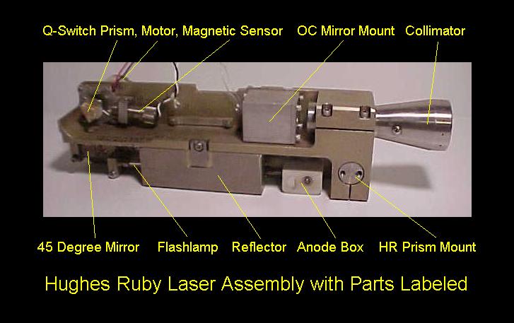
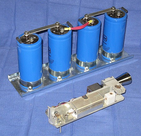
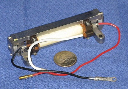
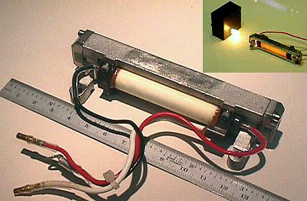
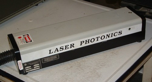
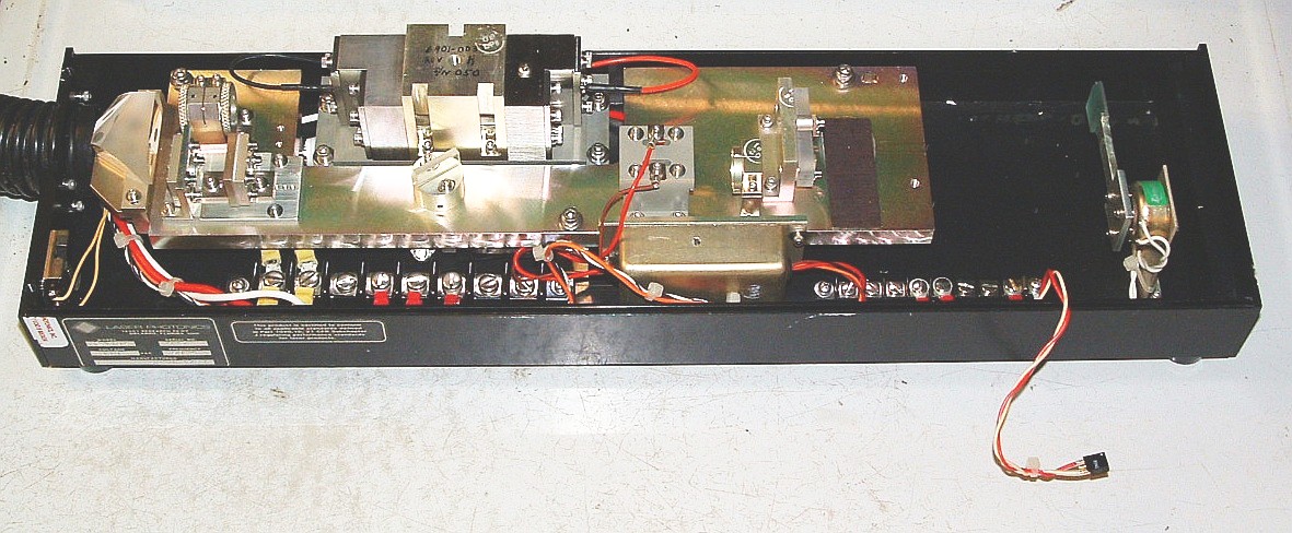
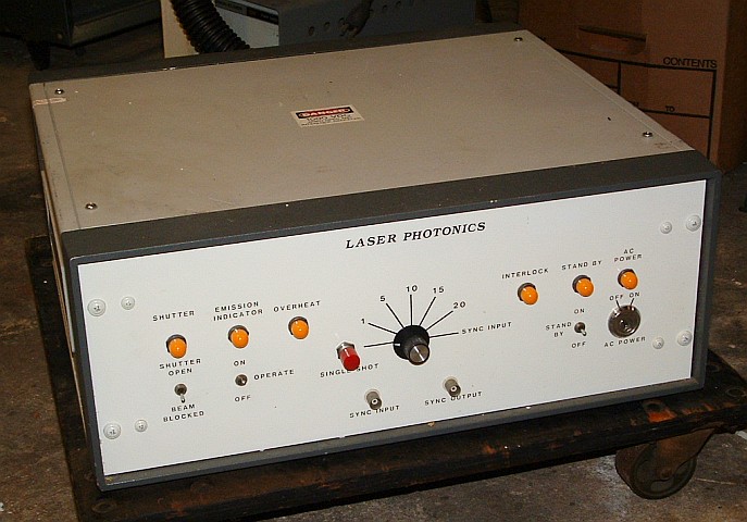
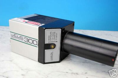
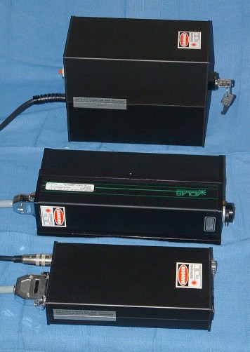
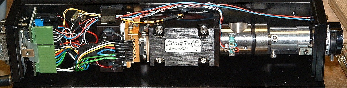
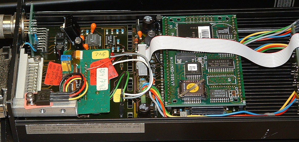
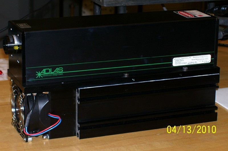
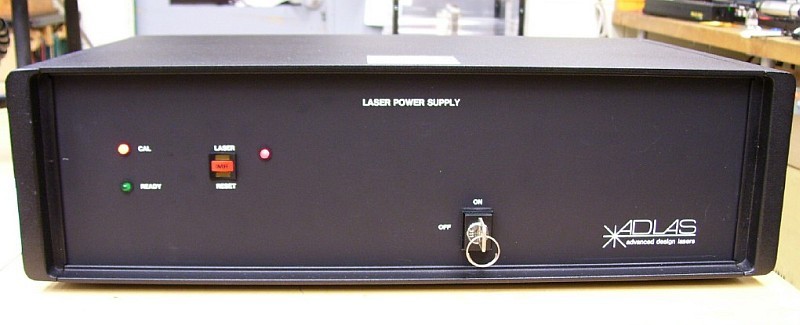
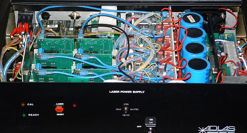
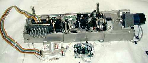
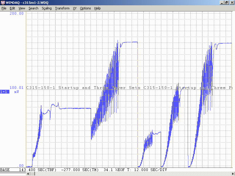
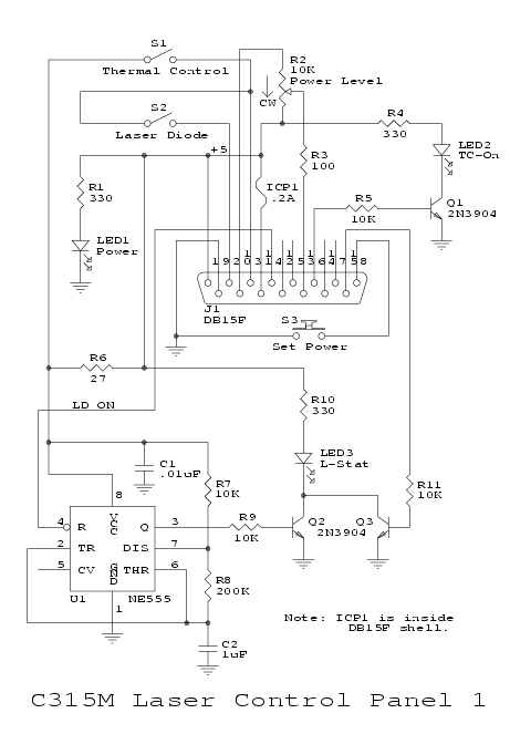
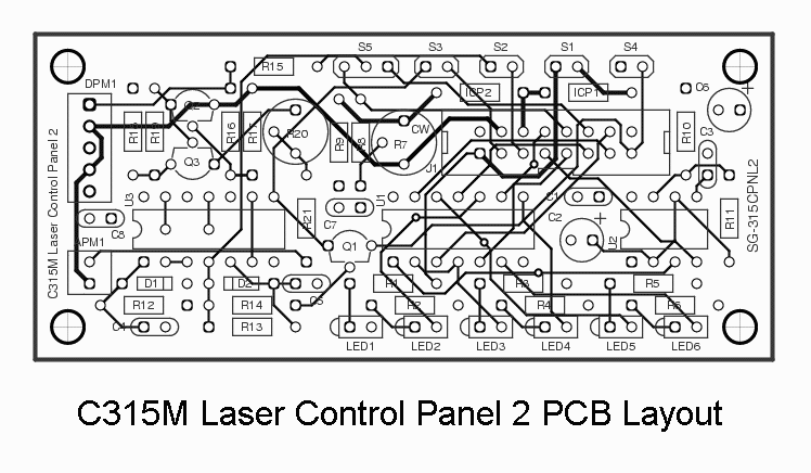
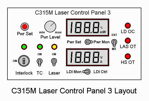
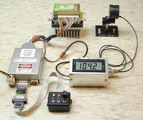
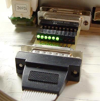
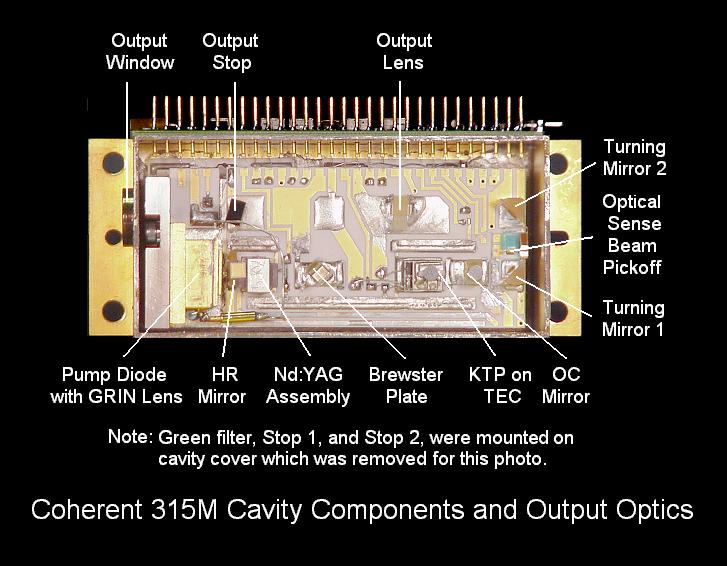
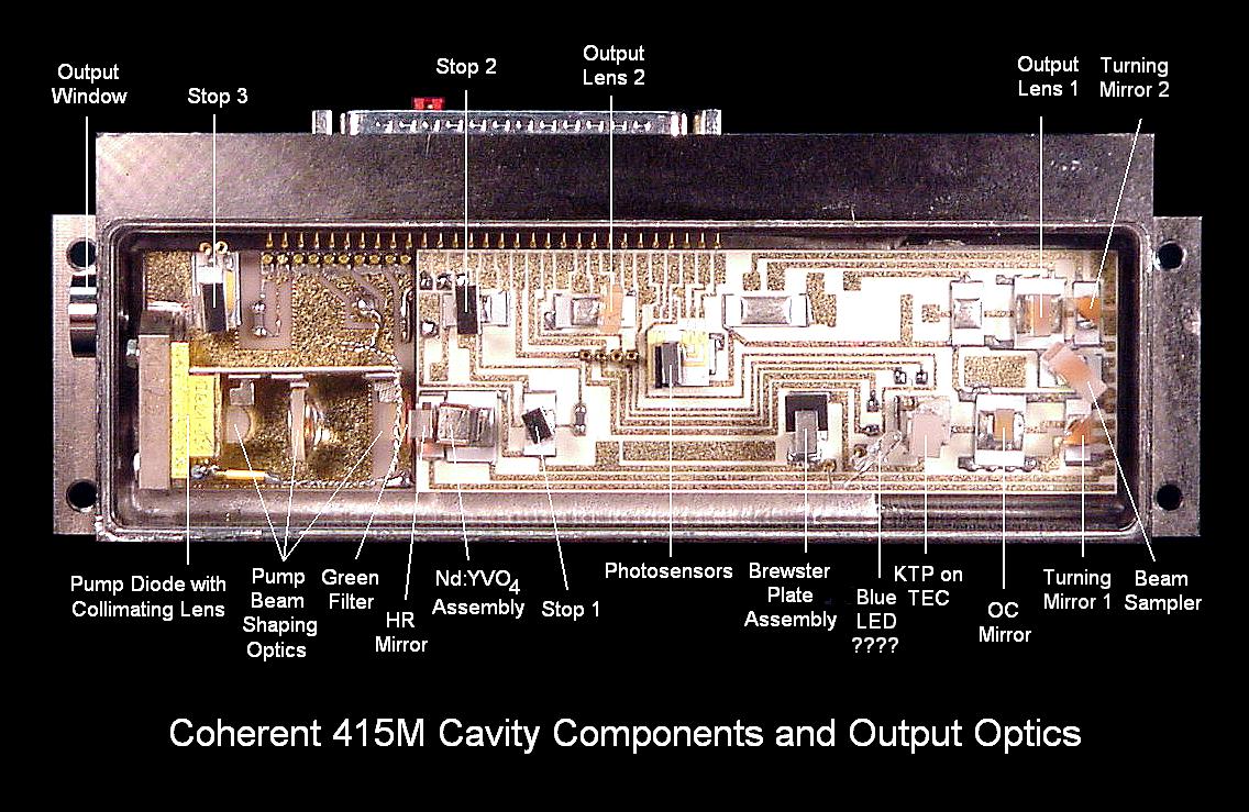
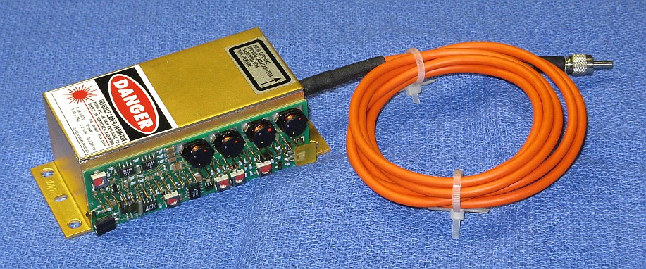
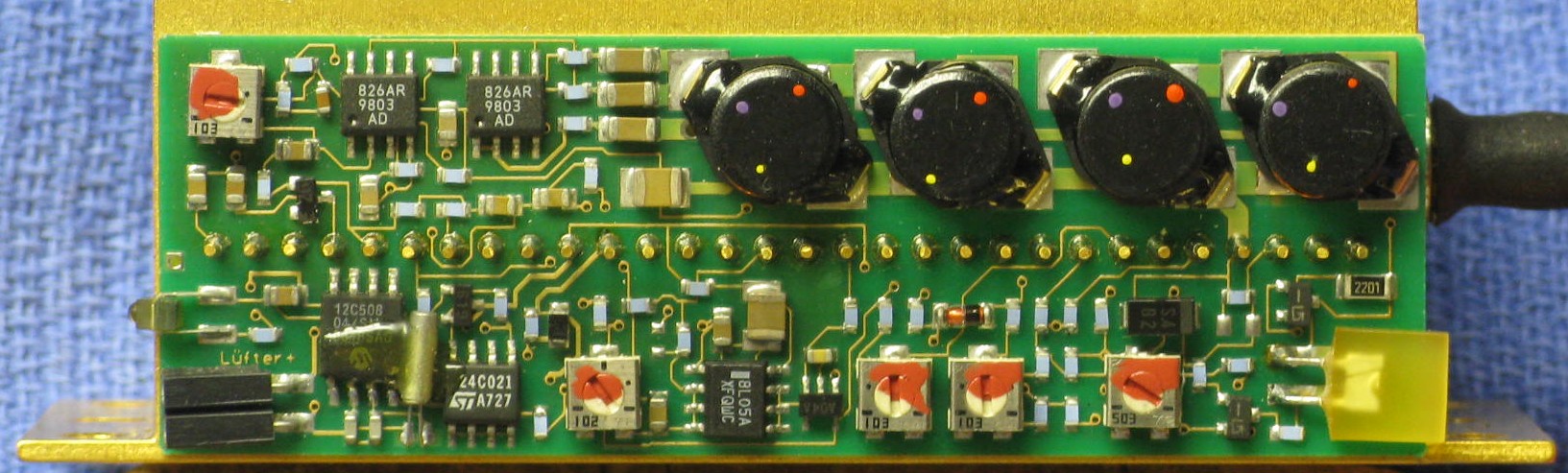
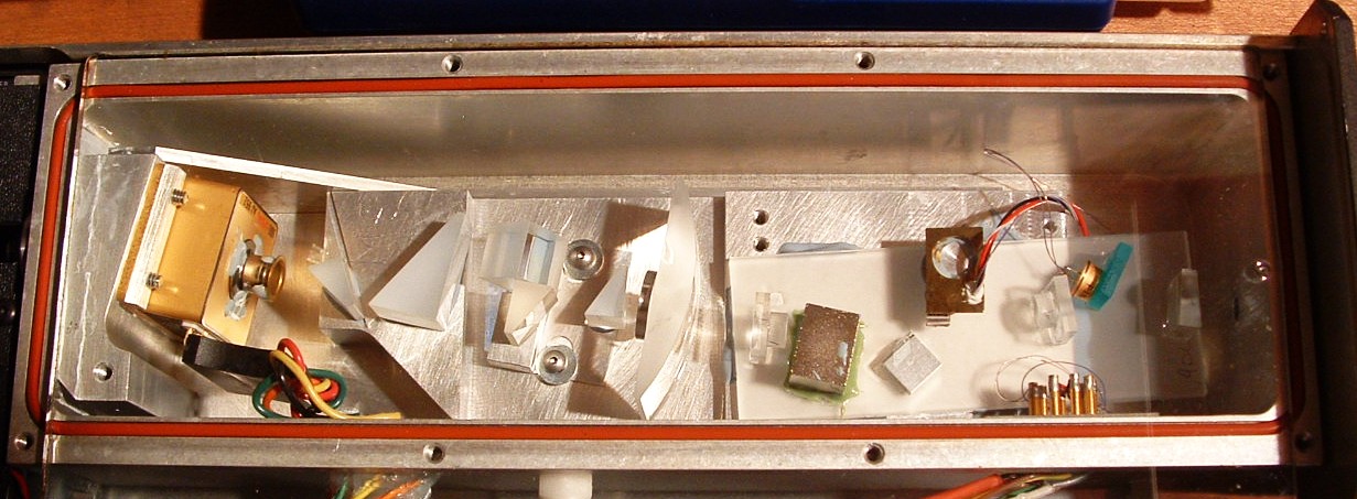
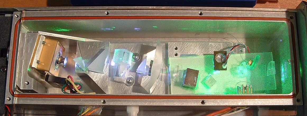
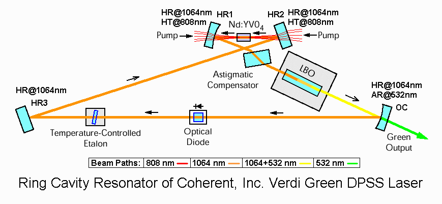
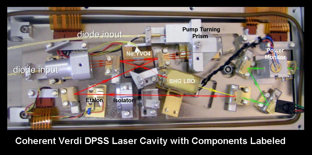
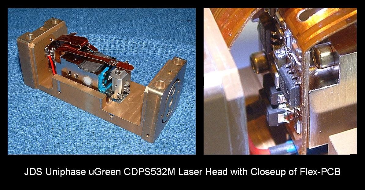
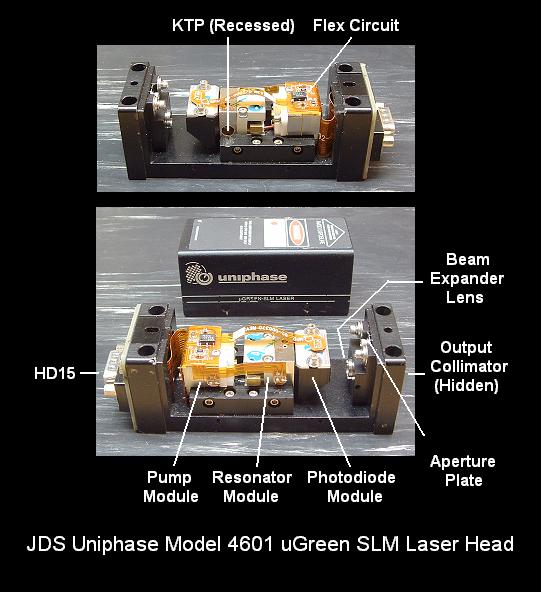
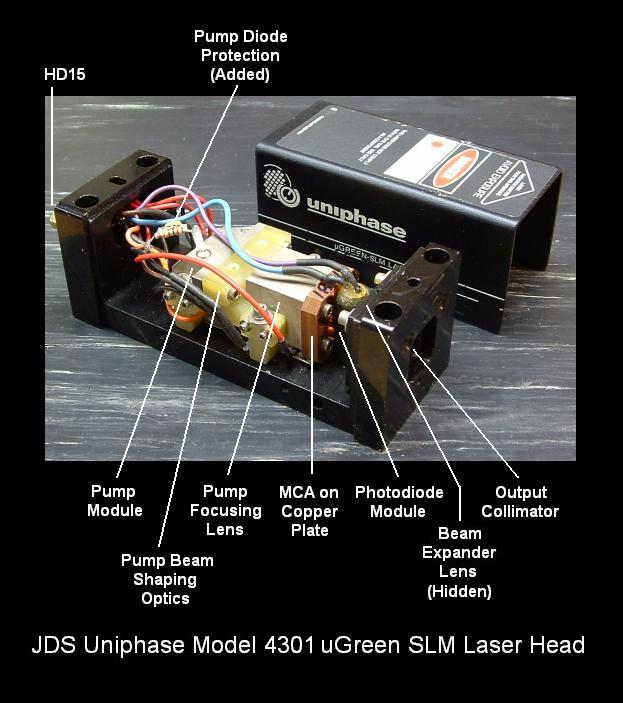
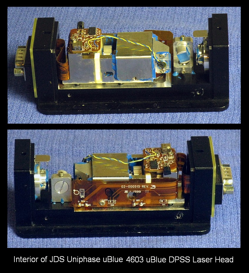
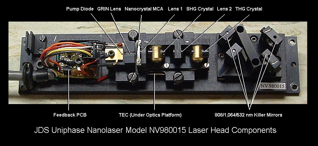
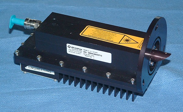
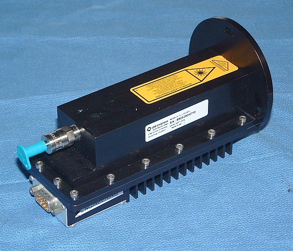
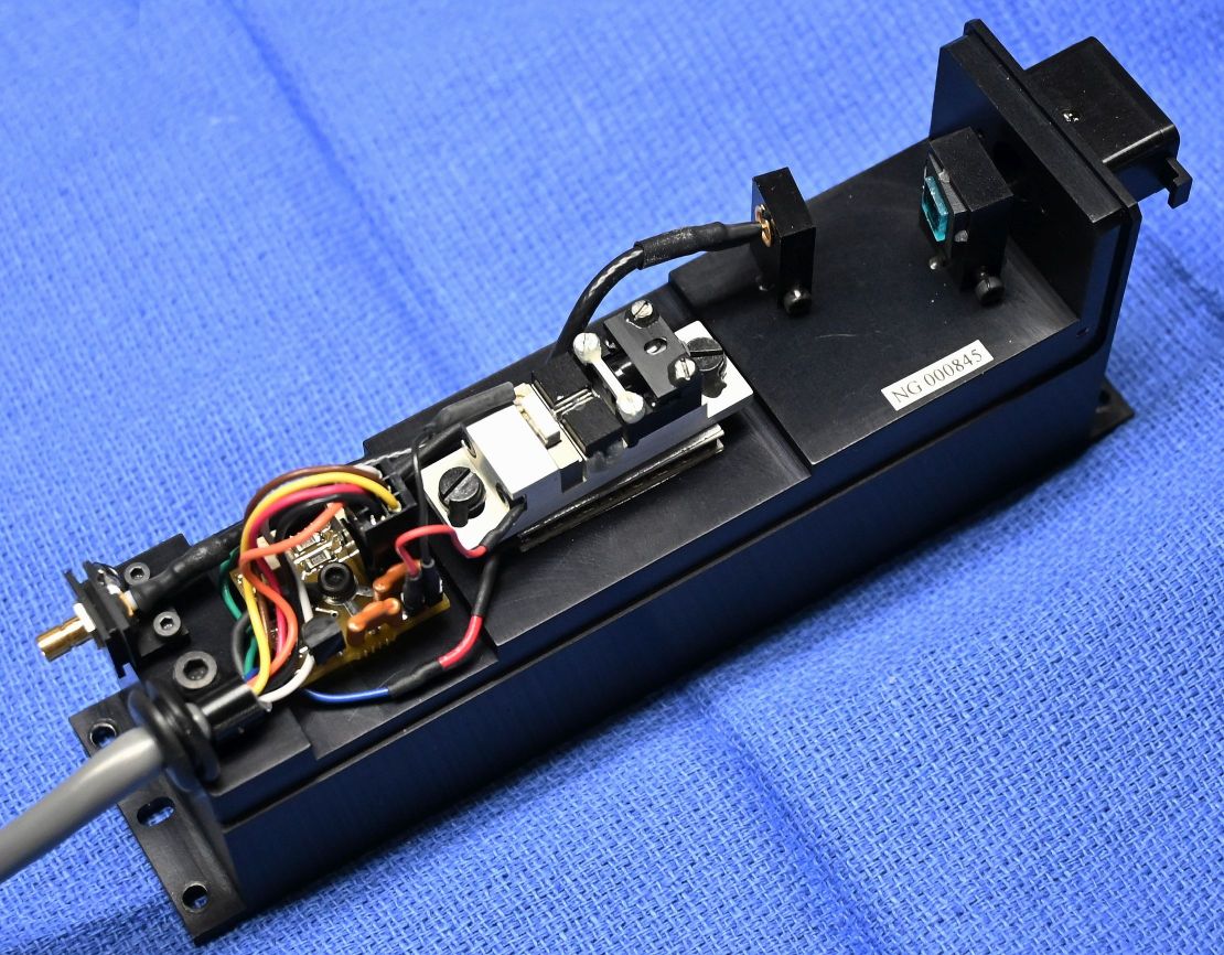
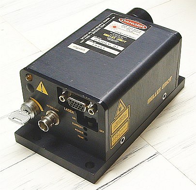
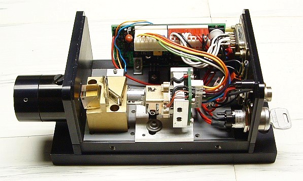
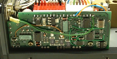
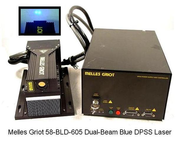
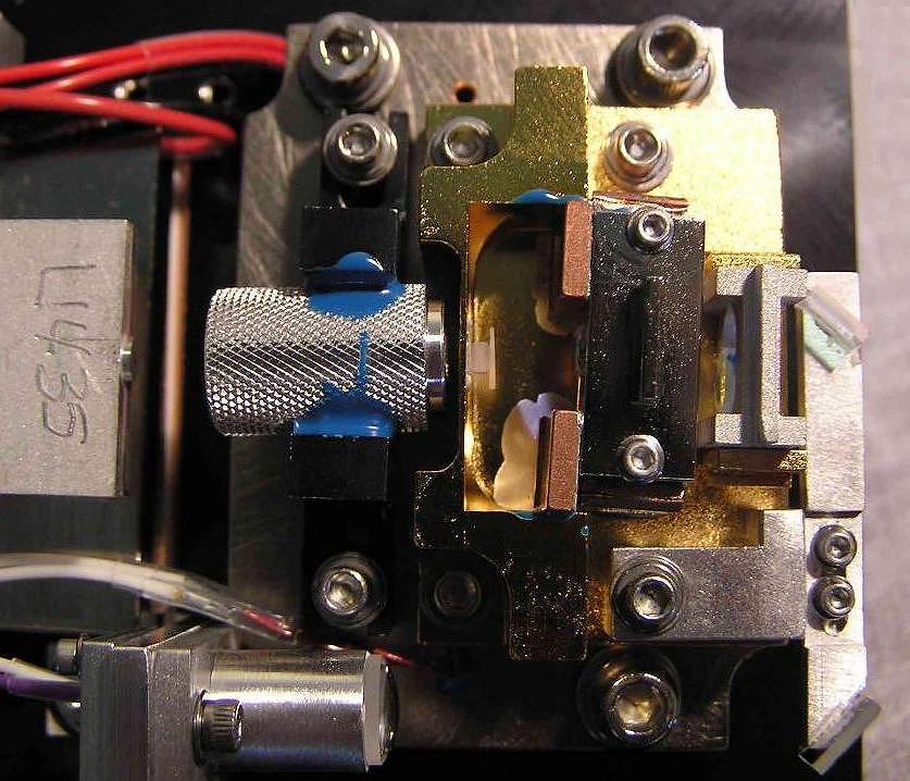
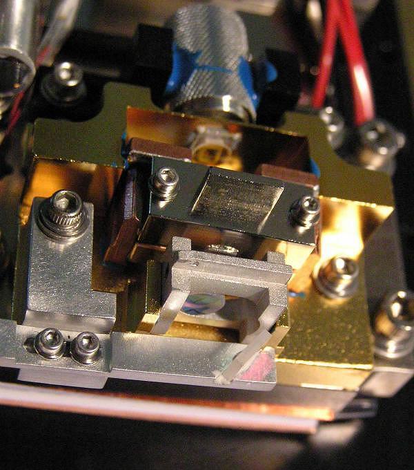
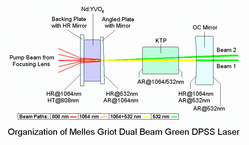
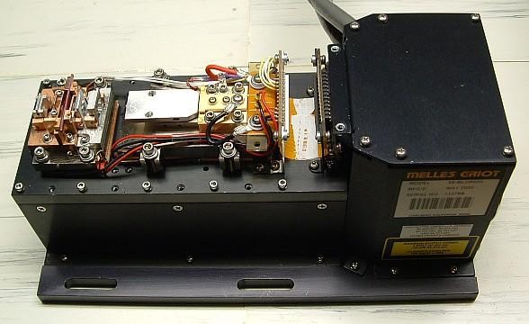
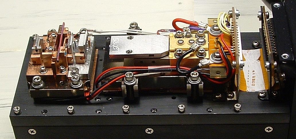
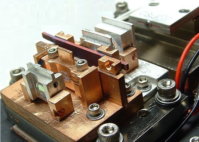
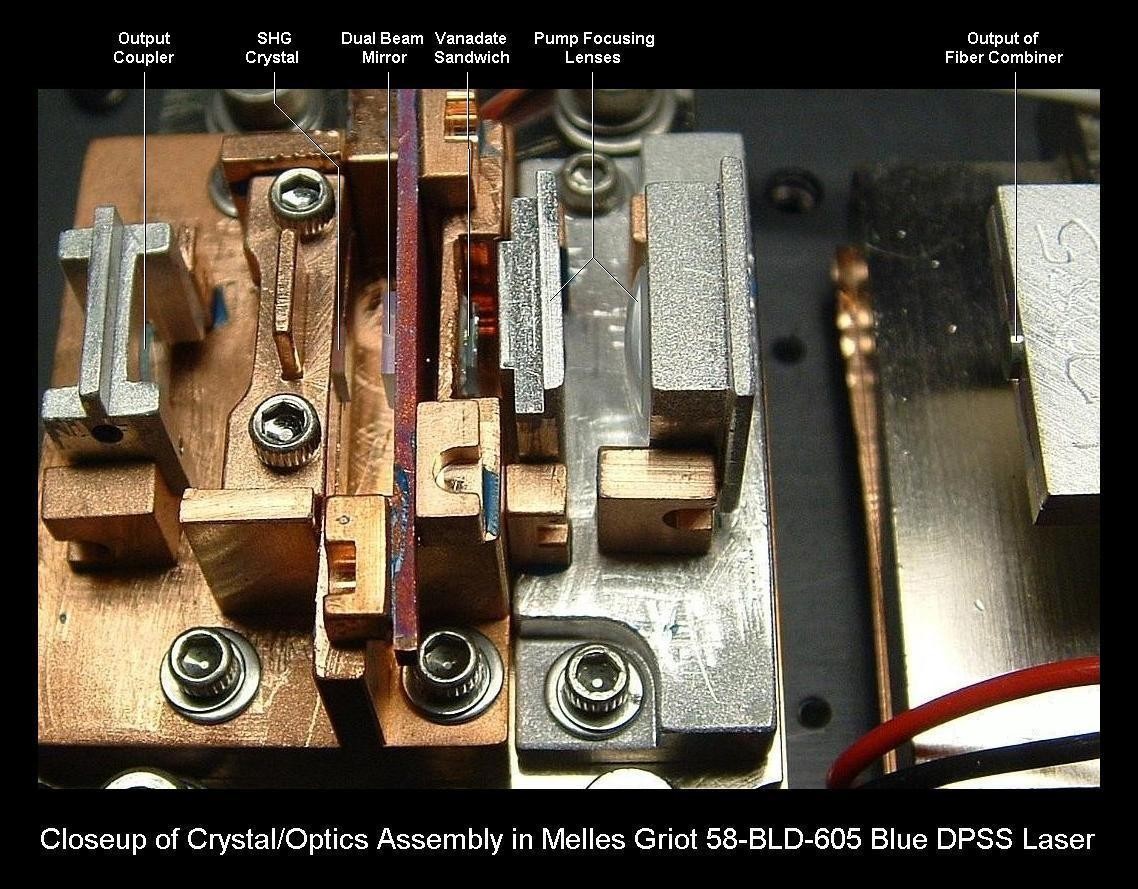
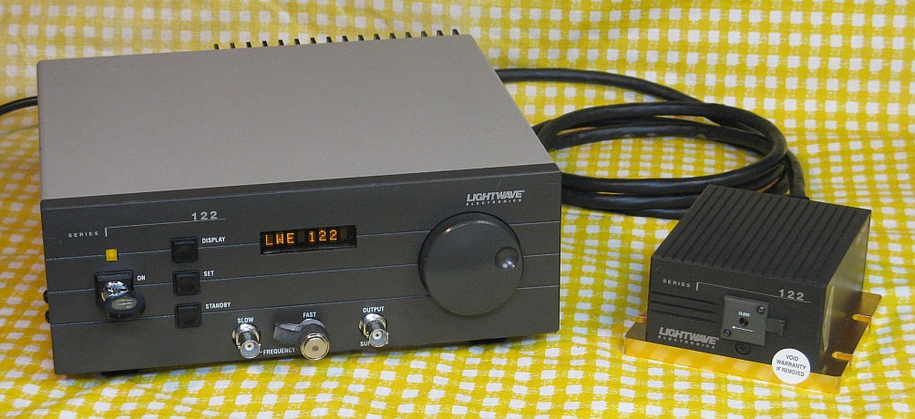
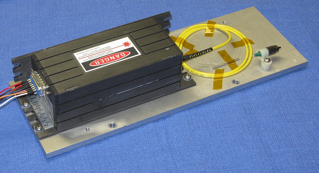
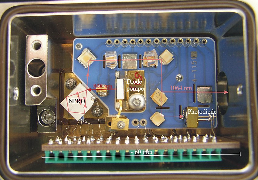
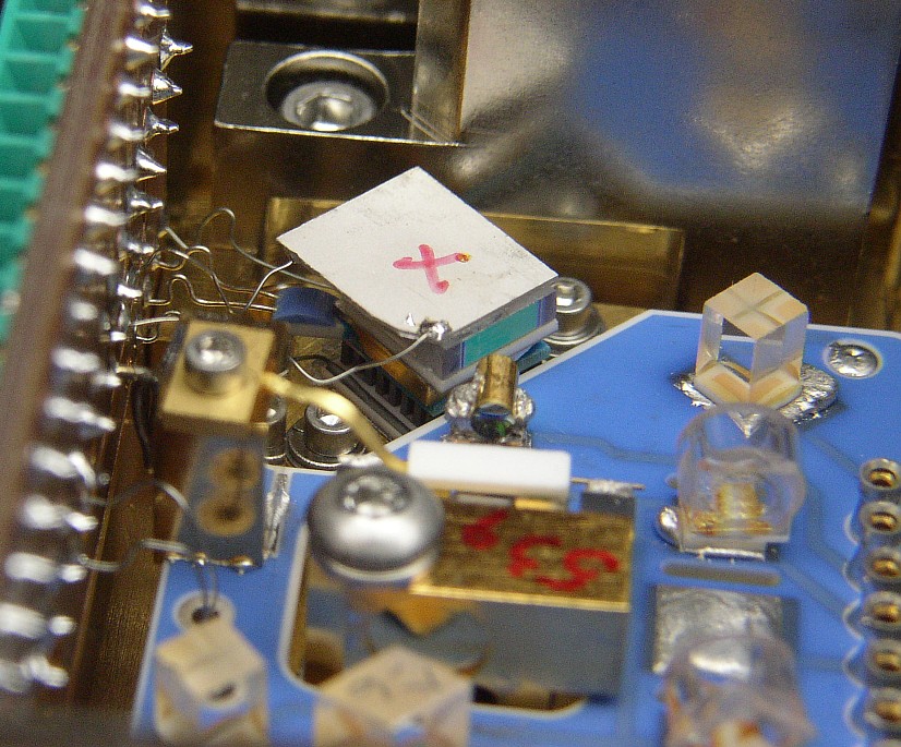
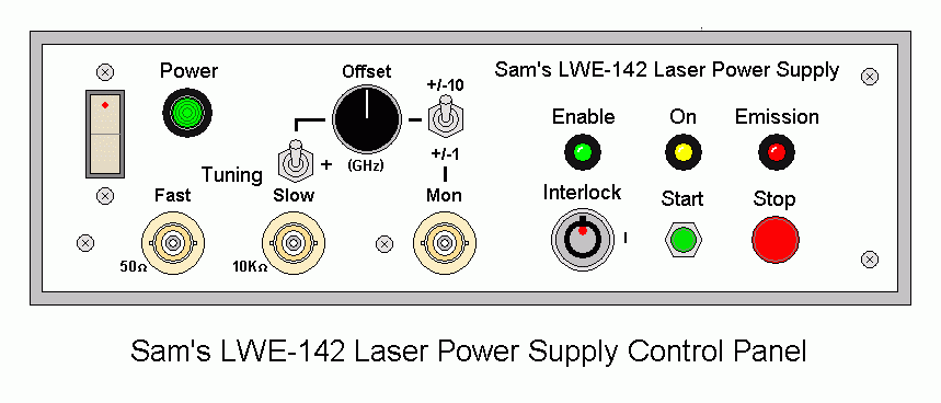
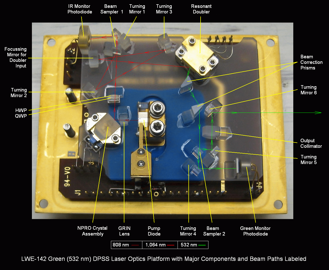
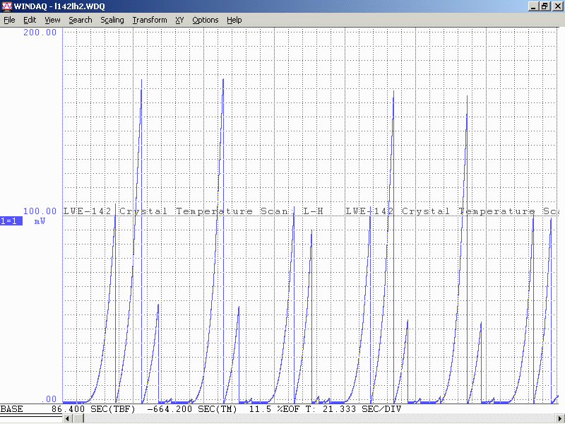
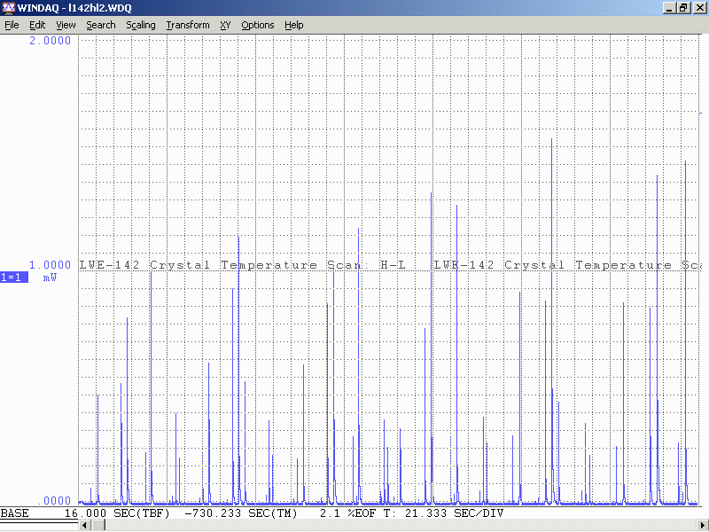
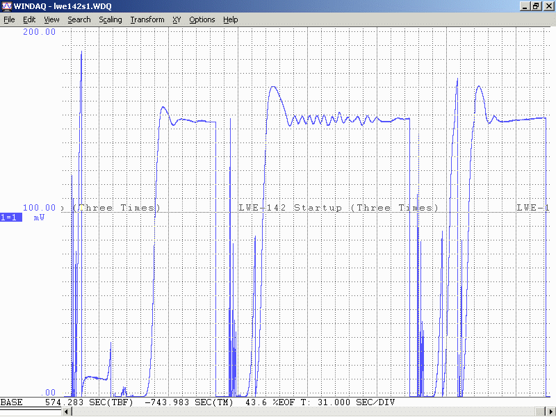
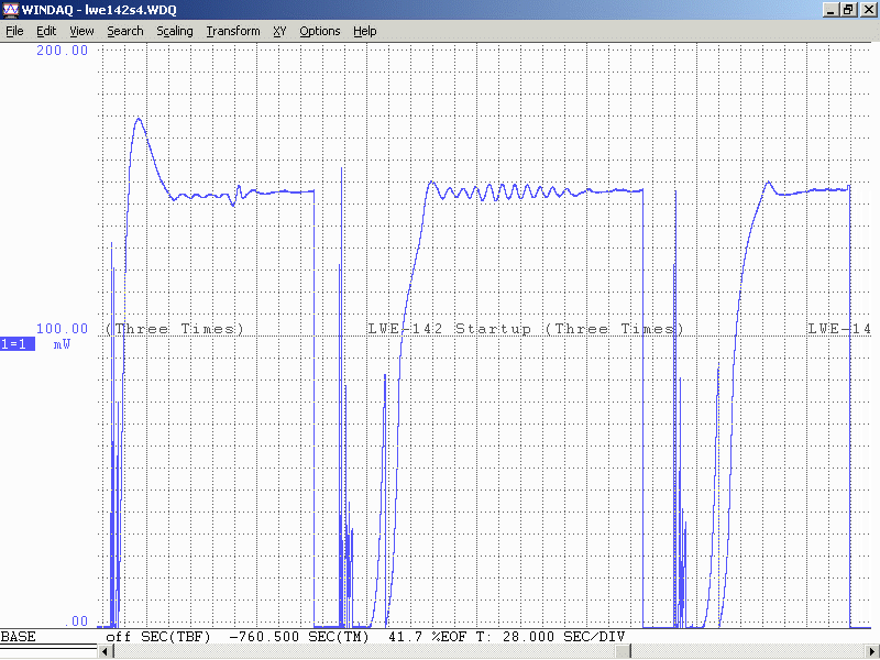
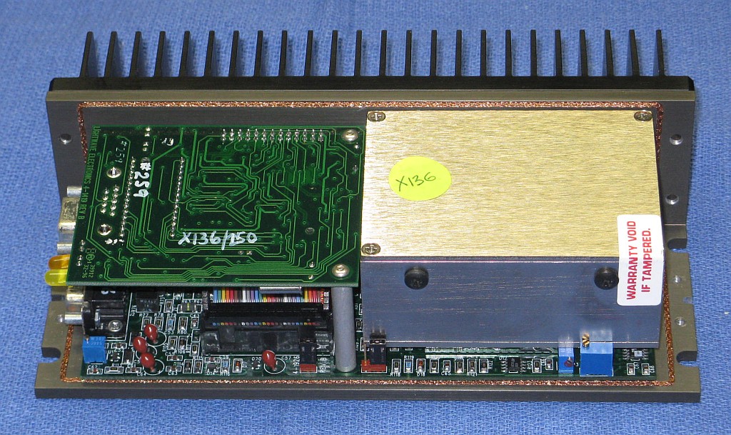
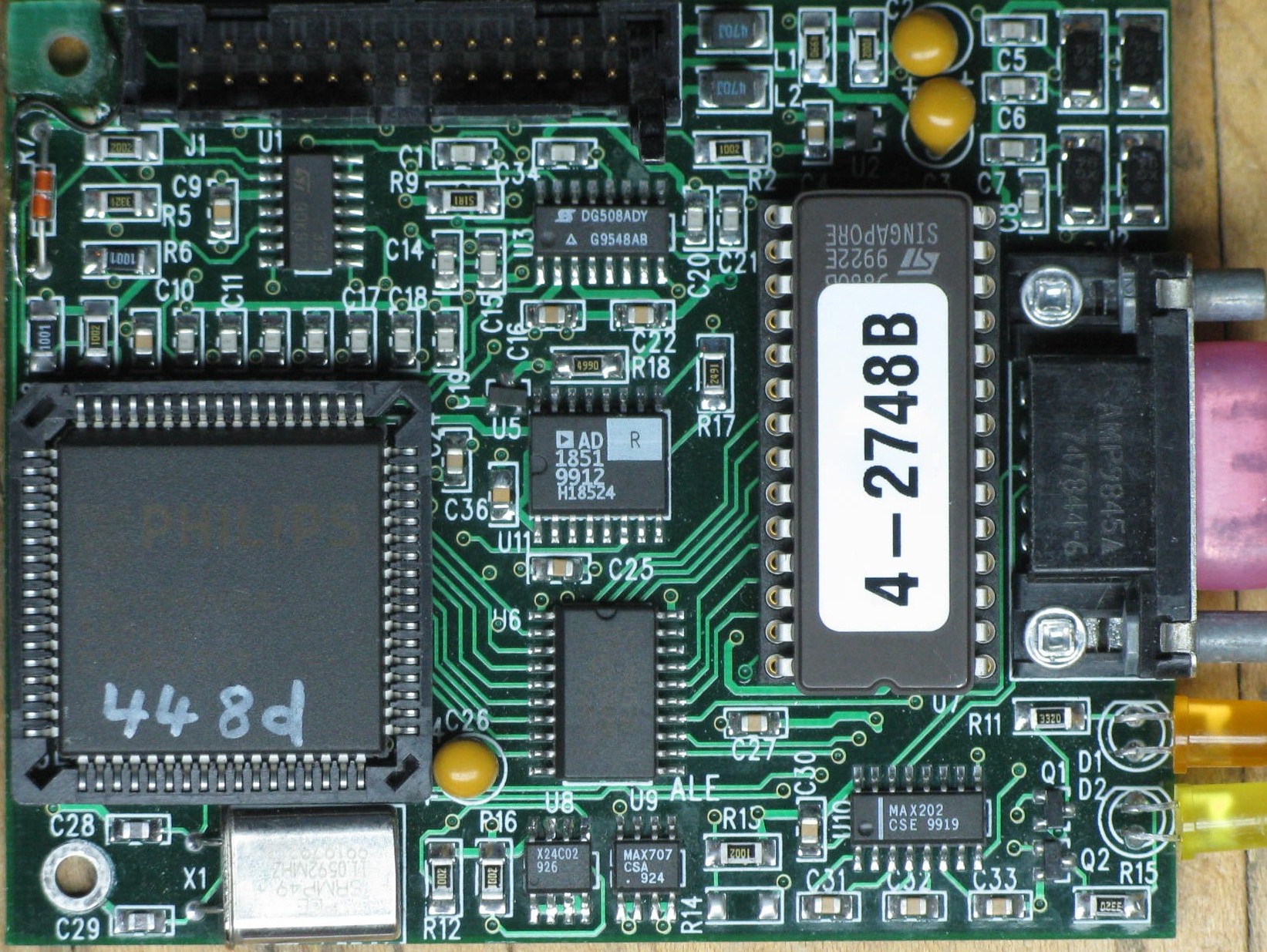
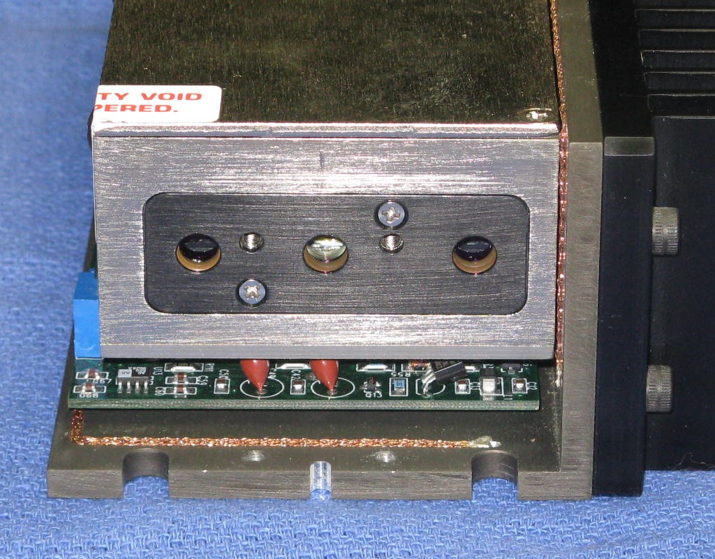
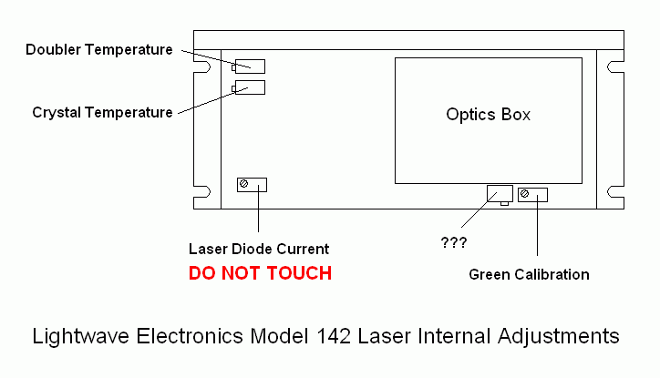
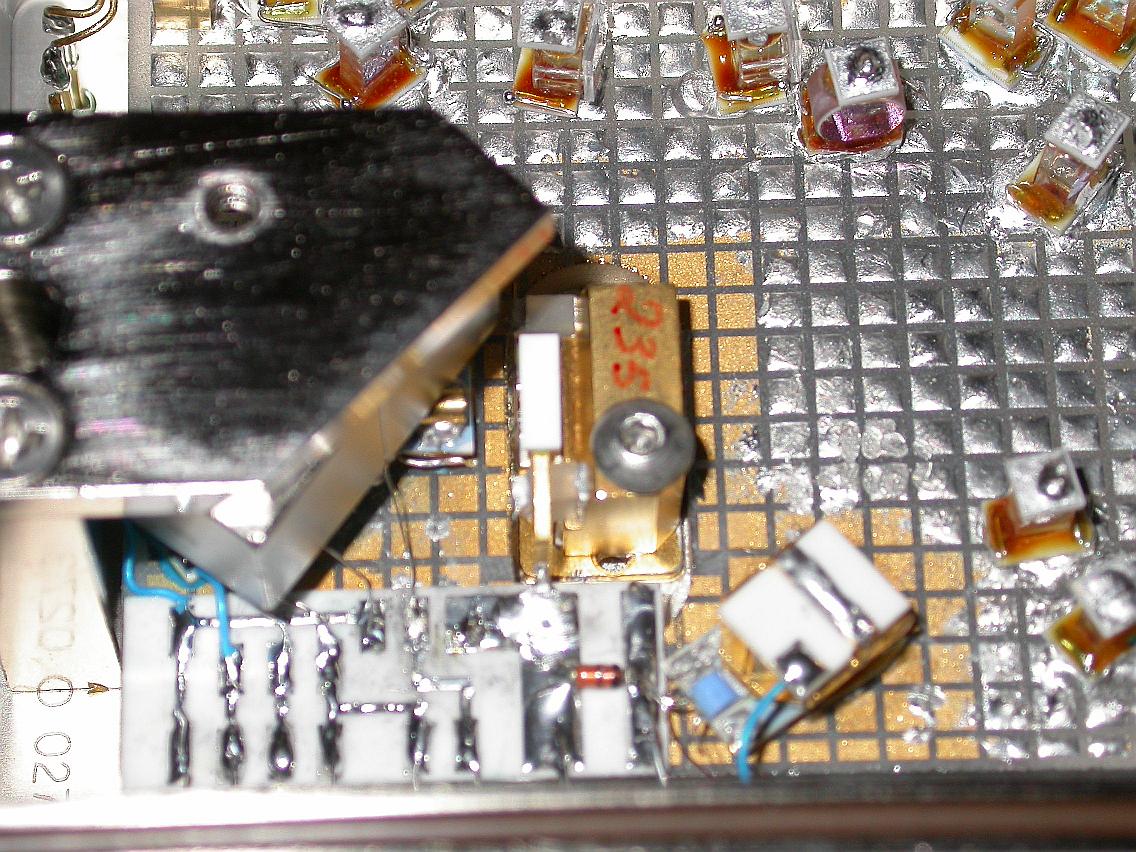
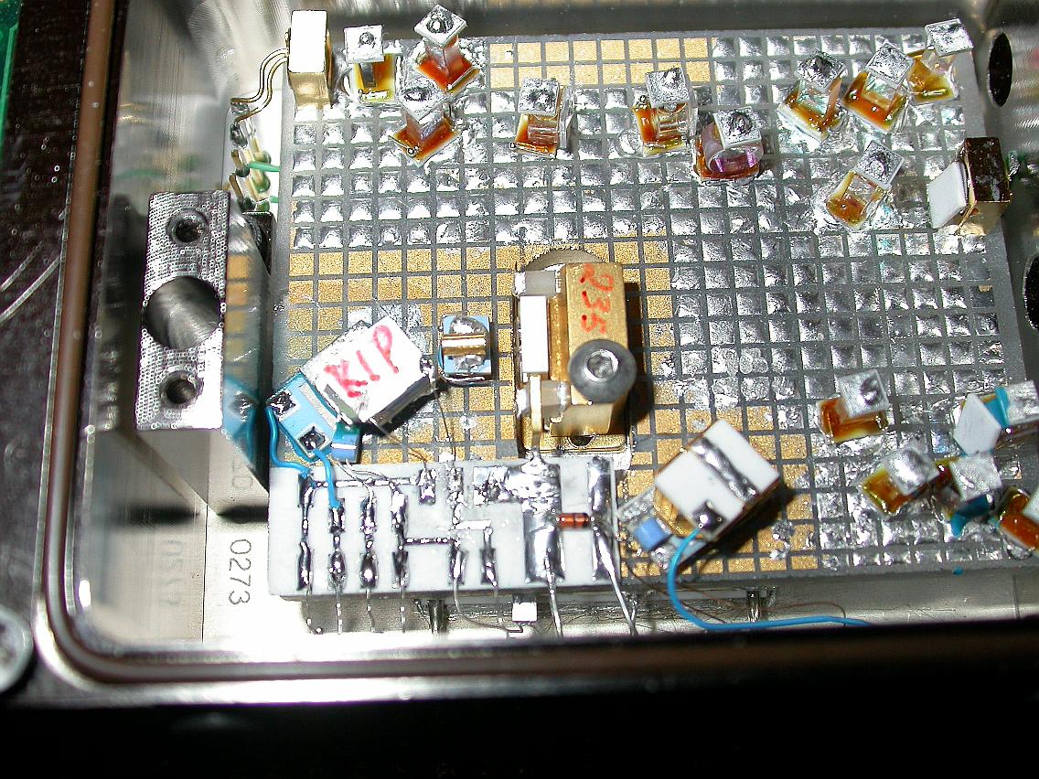
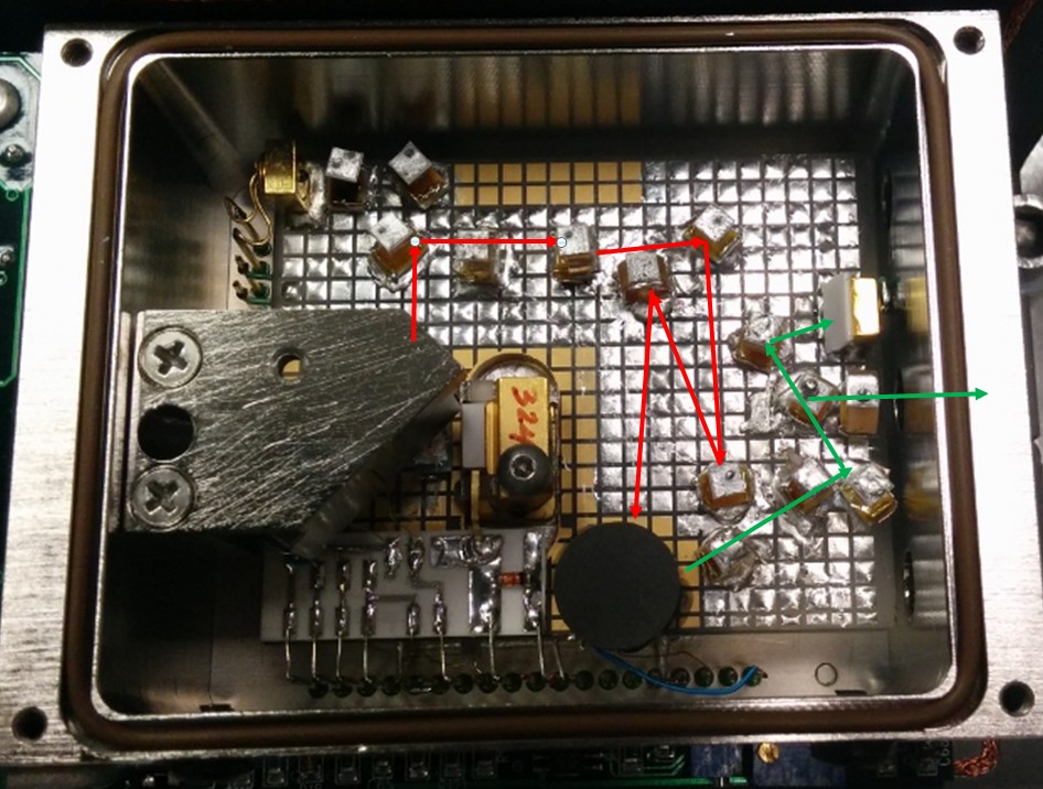
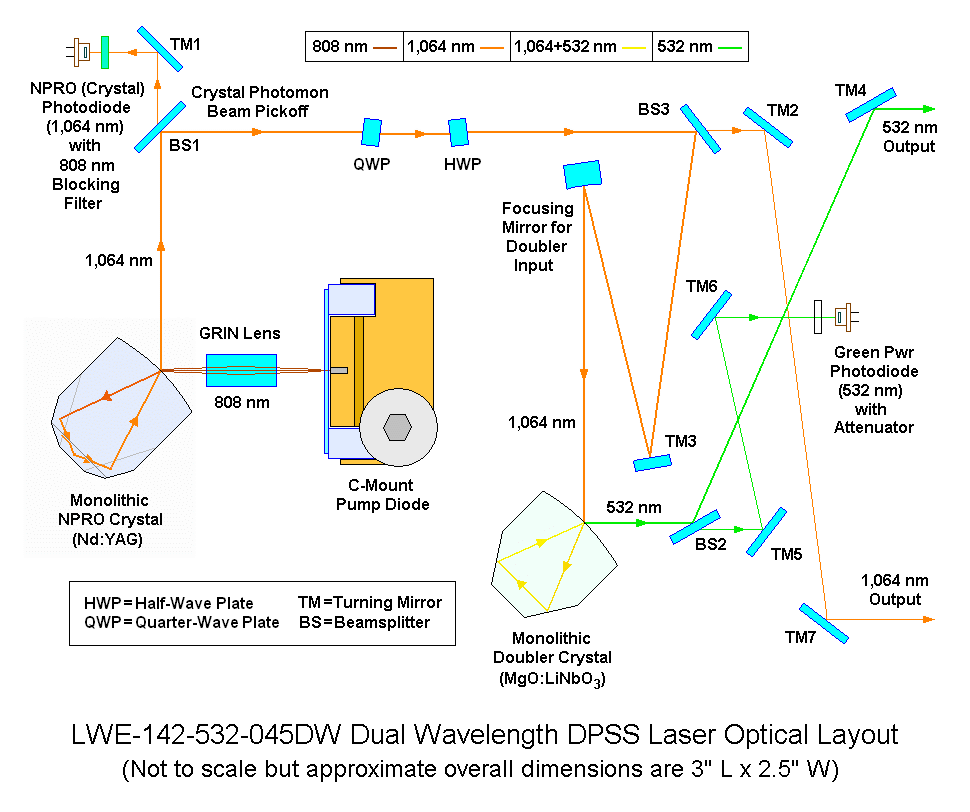
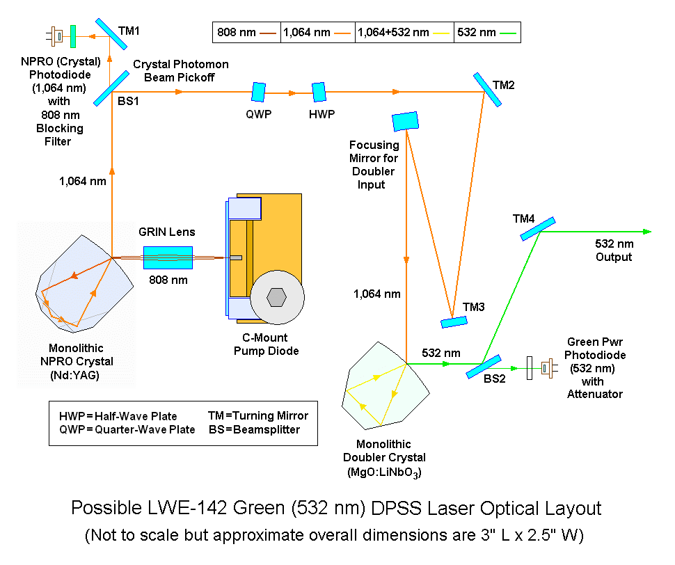
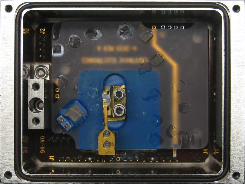
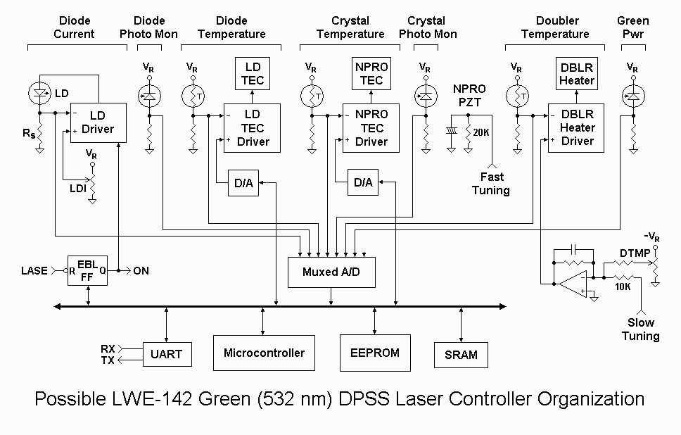
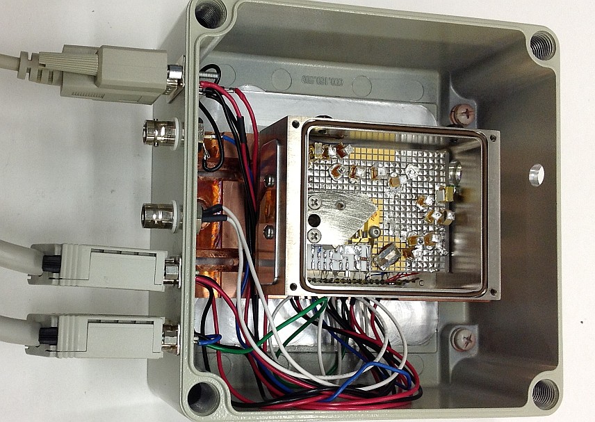
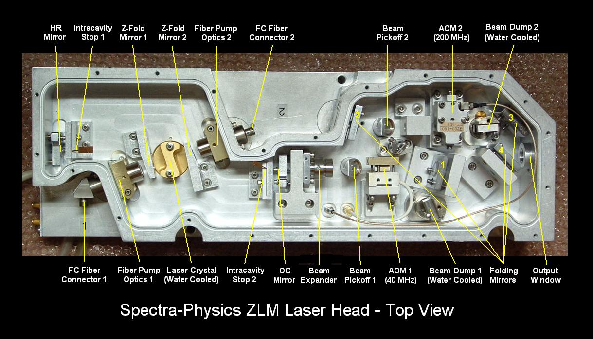
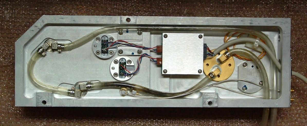
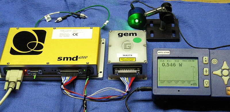
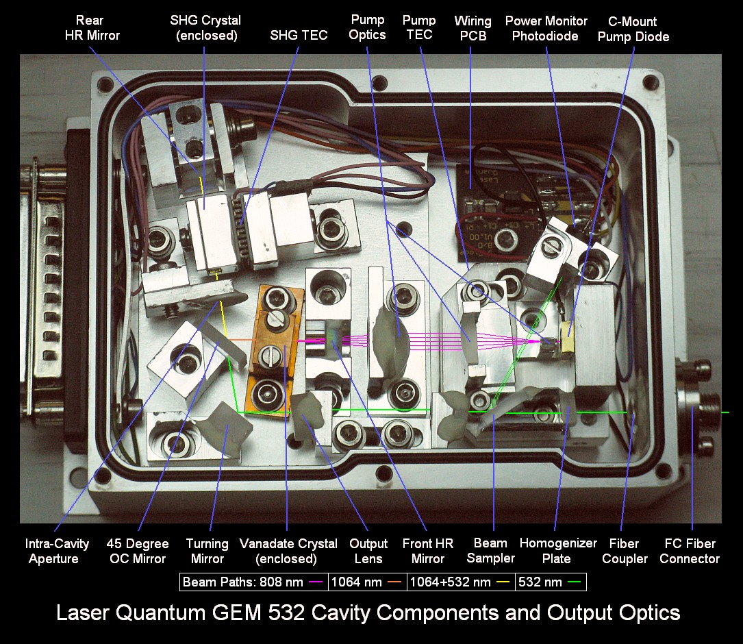
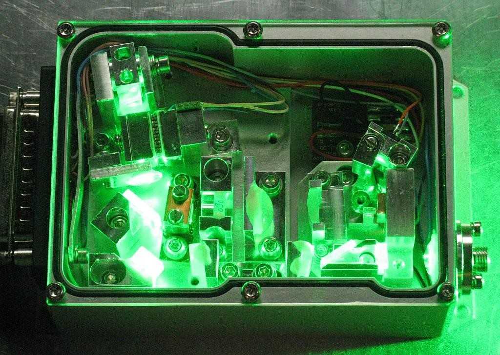
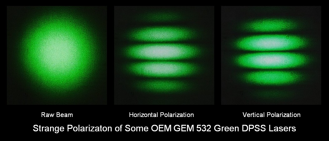
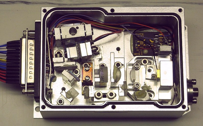
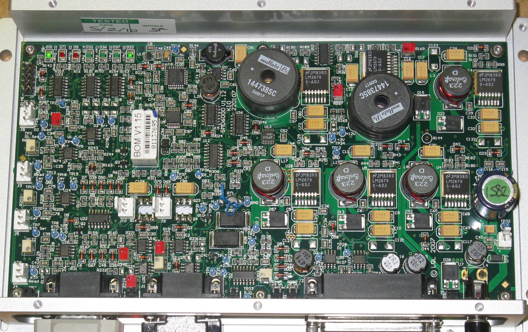
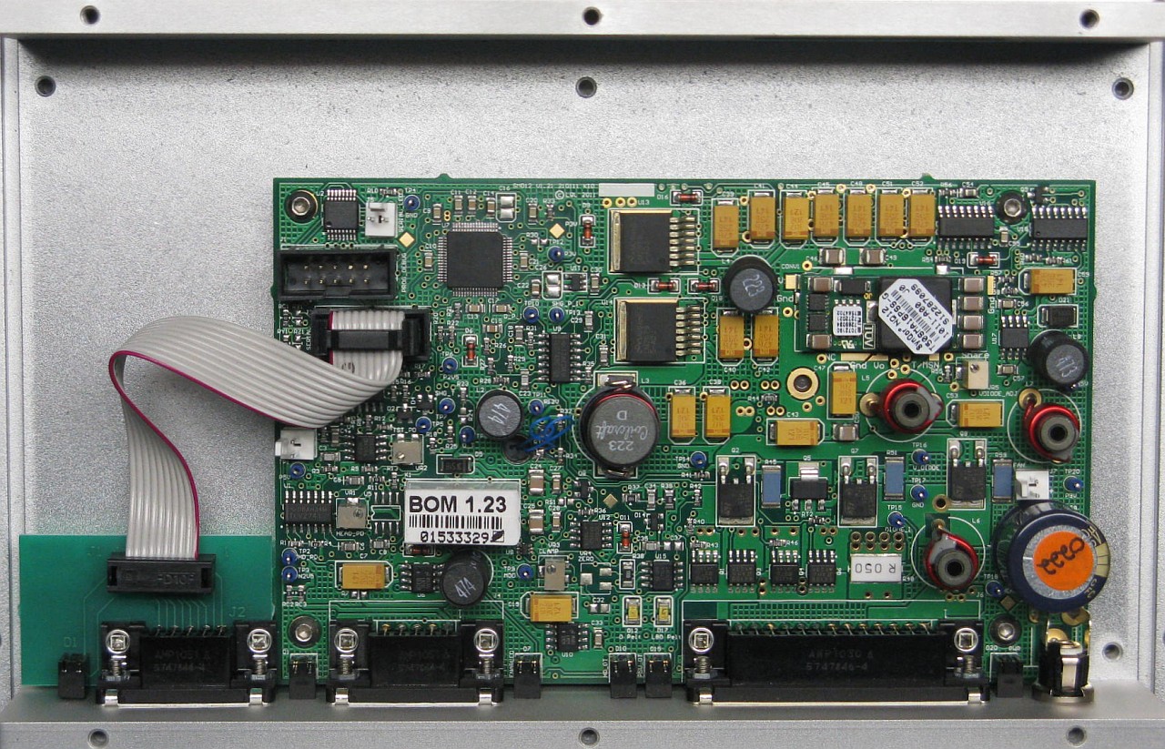
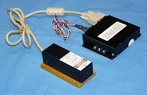
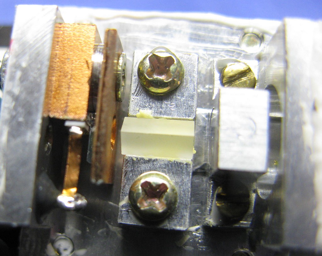
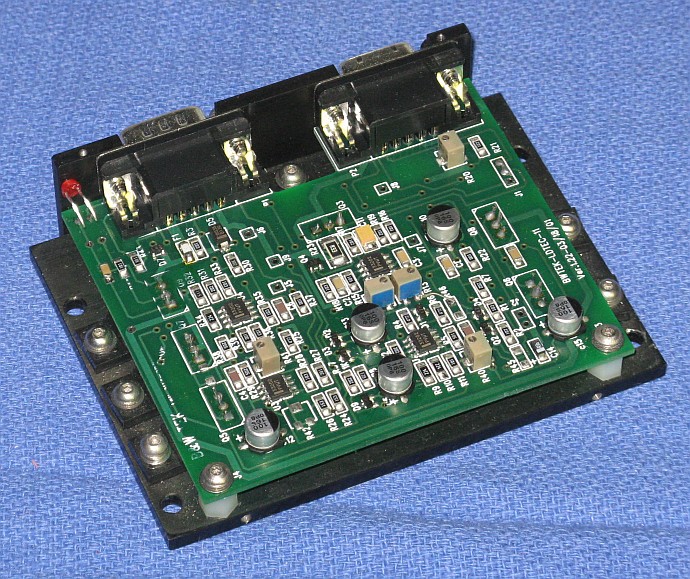
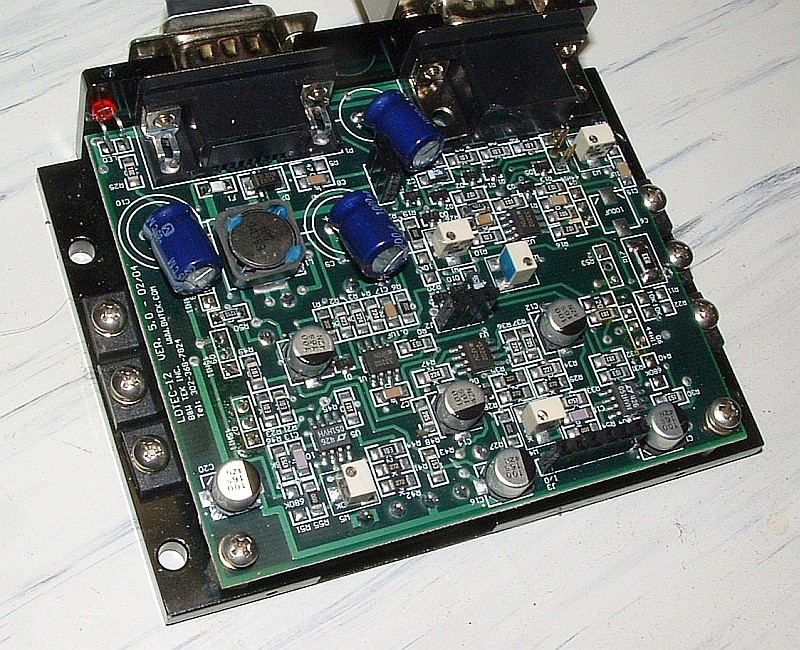
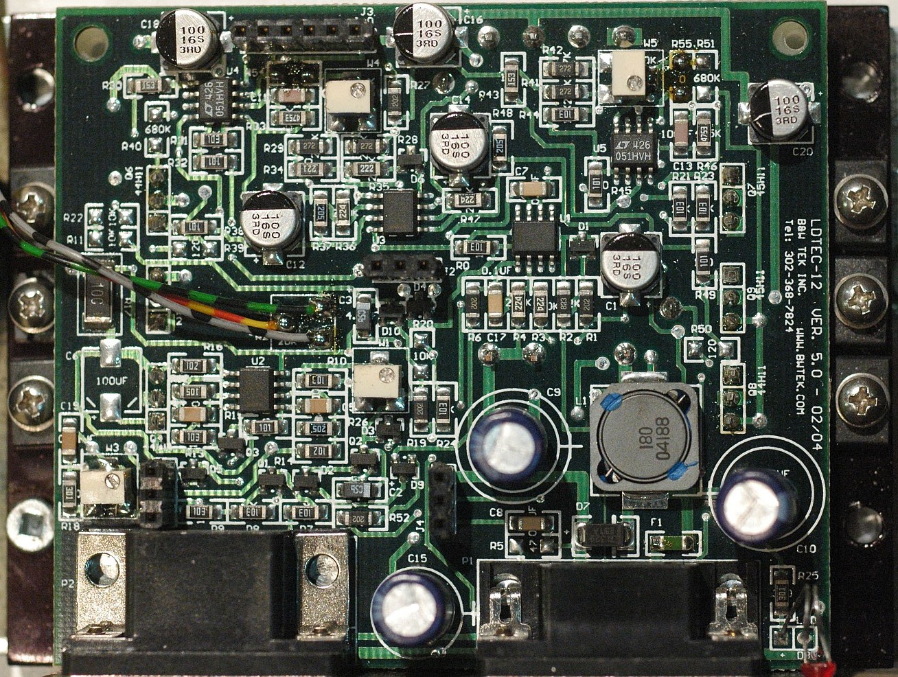
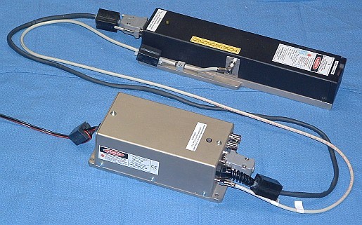
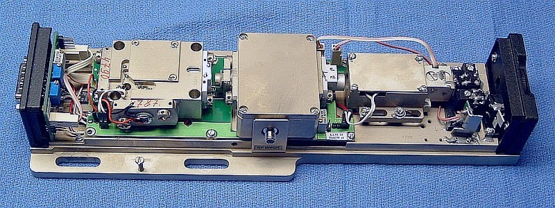
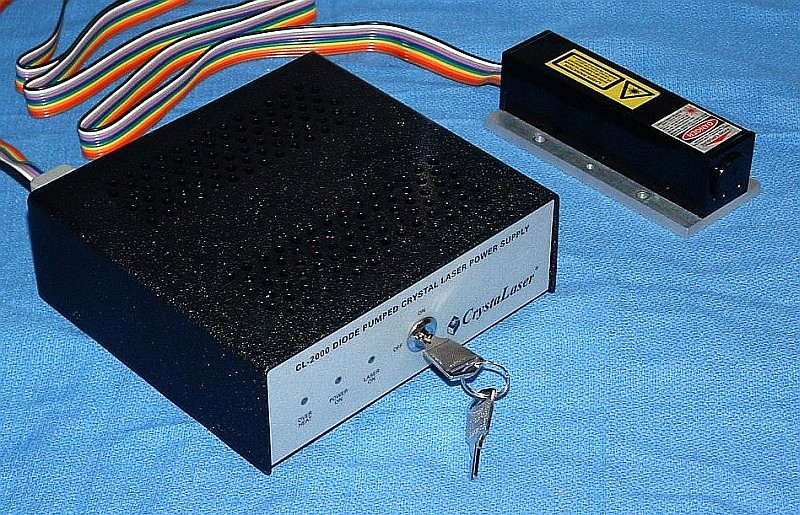
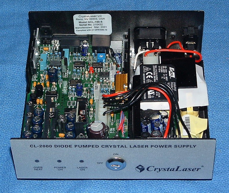
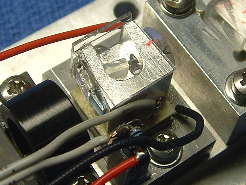
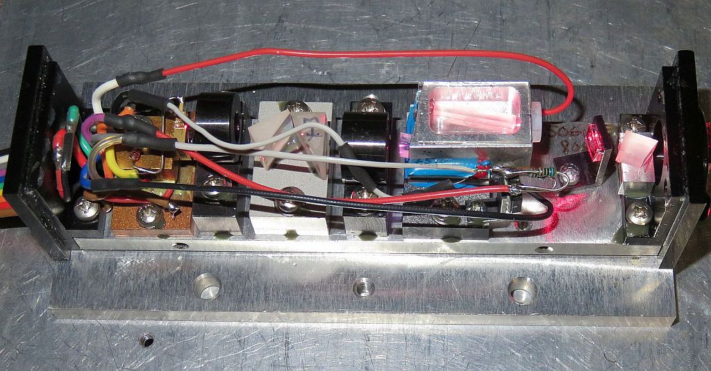
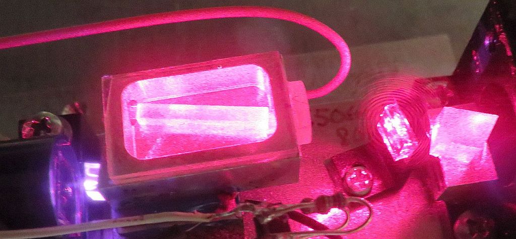
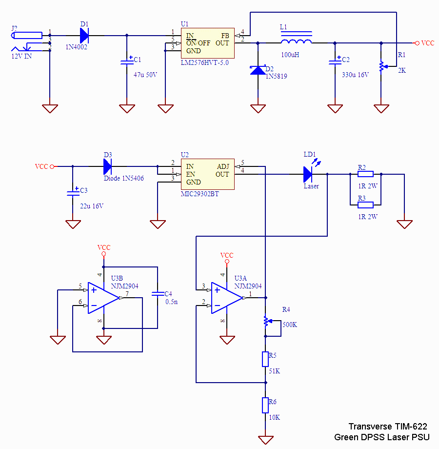
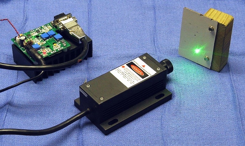
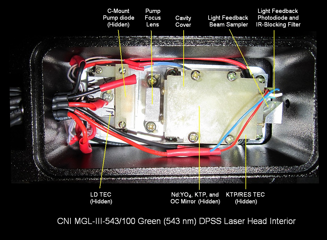
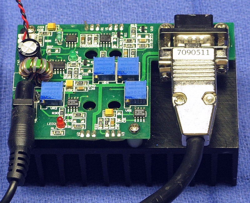
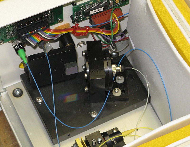
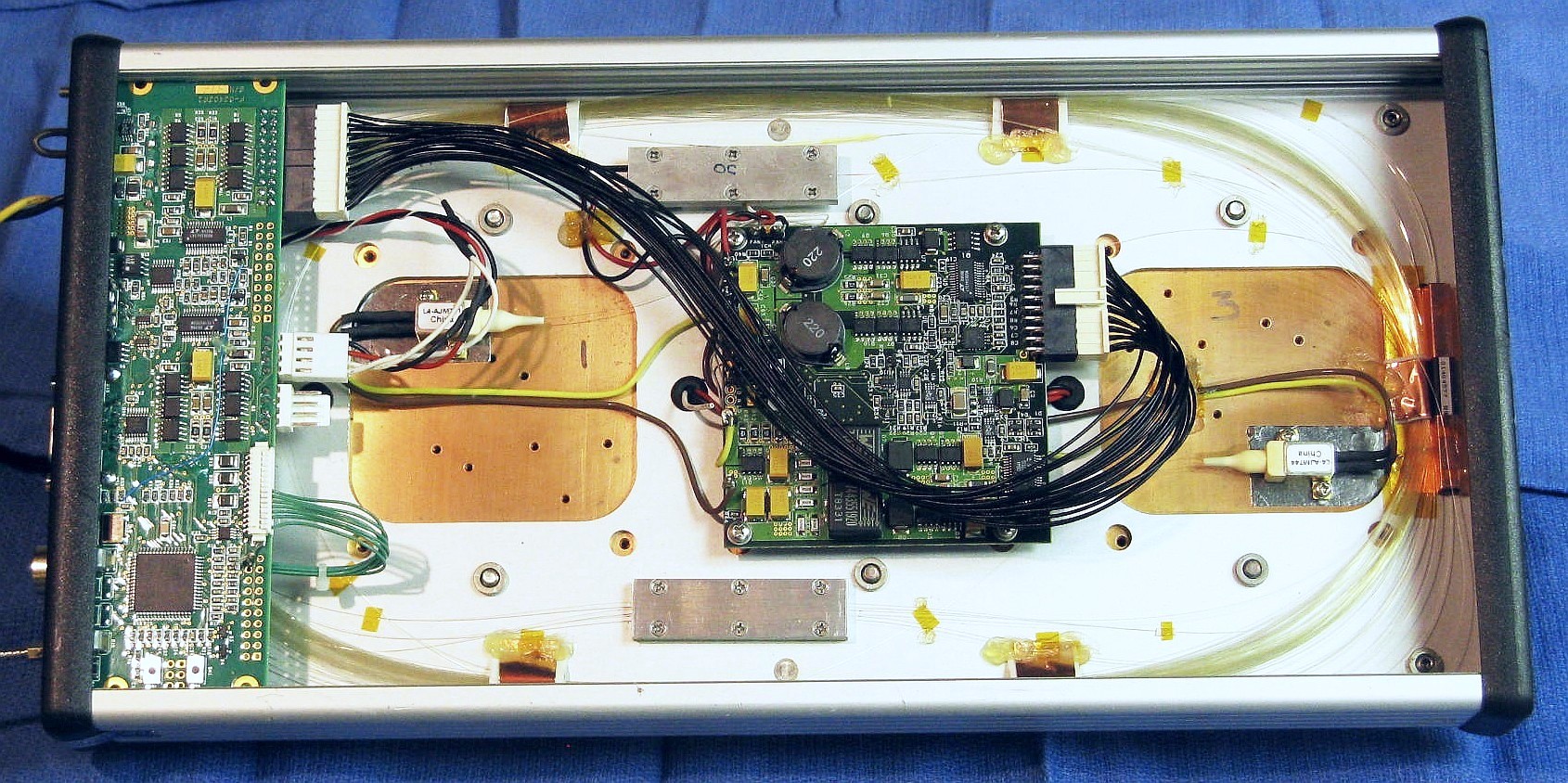
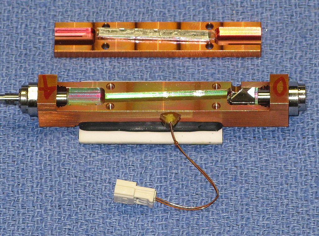