Compared to all the other home-built lasers, the nitrogen laser also likely has the lowest risk of failure IFF you stay pretty close to the SciAm design, more below. No glass working, no mirrors, mirror mounts, or mirror alignment, minimal vacuum. Despite this, what you end up with isn't substantially inferior to a commercial unit costing many kilobucks. It just lacks the convenience features and other bells and whistles. Now, the UV output isn't in a tight high quality beam like that of an HeNe or CO2 laser but it is a real laser. So, despite the high peak power, due to the lack of beam quality, the N2 laser isn't going to be good for materials processing since it is very difficult to focus the N2 laser beam to a small spot. However, it can be used to pump a dye laser and for all sorts of other applications requiring intense UV (and safety precautions must be taken to guard against excessive UV exposure).
However, despite the apparent simplicity of the N2 laser, don't be tempted to improvise before you get the SciAm design to lase. Even this simple laser can't just be thrown together (despite what you might think from the humor in the section: Nitrogen Laser Construction on a Shoestring - this should not be taken seriously). Start out with the same dimensions, materials, and construction techniques, and success is almost certain. While the SciAm N2 laser is not necessarily optimal or the highest power possible, it does work. Bigger is not necessarily better (or higher power but may actually be 0.00 power. You can't just increase the size of the capacitors and laser tube and expect it to do anything useful). Once your N2 laser is operational, feel free to go hog wild experementing. But even then, change only one thing at a time!
In case you are wondering, N2 lasers do have their uses besides being a good first laser for the home-built laser enthusiast. These include: optical pumping of dye lasers, UV spectroscopy, non-destructive testing, fluorescence measurements of materials, and measurements of very fast processes (nanosecond UV strobe for high speed photography). Perhaps, these are not as glamorous as laser light shows and laser welding, but important applications nonetheless!
(From: Jon Singer, of the Joss Research Institute.)
The molecular nitrogen laser was discovered by H. G. Heard, who published an article about it in Nature in 1963. The first nitrogen lasers produced only a few watts, but people soon began to optimize them, and maximum power of at least 5 MW is possible in a realistic discharge-pumped device, with maximum pulse energies of about 20 mJ. Higher powers have been reported in discharge-pumped nitrogen lasers, but have not been reproduced. Electron-beam pumping is also possible. Nitrogen emits primarily at 337.1 nm, but is also reported to put out a small proportion of its energy at 357.6 nm, and there is a peak in the IR, which can apparently comprise as much as 20% of the output under some conditions. Although nitrogen lasers have been operated over a range of partial pressures from a few Torr to more than 1 atmosphere, it is common to divide them into two categories: low pressure and atmospheric pressure. (Atmospheric pressure nitrogen lasers are almost always excited transversely, and fall into the general category o f lasers.) The upper-state lifetime of nitrogen is inversely related to pressure; it is approximately 40 nsec at pressures of a few Torr, decreasing to perhaps 2 nsec at 1 atmosphere. Unfortunately, the lower laser level has much longer lifetime; this cause s, and the laser is self-terminating. This effect seriously limits both the duration of the pulse and the efficiency of the laser. Nitrogen is pumped by direct electron impact, typically in a pulsed electrical discharge; if the electrons do not have sufficietn long before they run out of headroom. Low-pressure nitrogen lasers typically emit pulses that are either 4-8 nsec long (most small devices and a few high-performance devices) or 10-20 nsec long (some high-performance devices). Atmospheric pressure nitrogen lasers emit pulses that are typically 600-800 psec long. Helium is a useful diluent, at least at low partial pressures; a 50-50 mixture of nitrogen and helium is reported to produce smoother and more reliable operation in low-pressure lasers, and some low-pressure lasers can even run when filled with 1 atmosphere of helium, to which is added a small partial pressure of nitrogen. Addition of electron-attaching gases, including SF6 and NF3, has also been reported to improve the operation, but these are not suitable for DIY use. NF3, in particular, is quite dangerous.
There is also a nitrogen ion laser, which runs in a very dilute He-N2 mixture. At least 4 lines have been reported with electron-beam pumping, some in the UV and some in the visible. With discharge pumping, the most prominent line typically seems to be at 428 nm.
For eye protection, low cost plastic (e.g., polycarbonate) safety glasses or wrap-around UV blocking Sun glasses should stop most UV but since these vary widely, it is essential to test your sample at the 337.1 nm N2 laser wavelength. Some goggles spec'd for CO2 lasers also have a UV-blocking range which includes 337.1 nm with adequate optical density. These tend to be much less expensive than other (perhaps $50) but may indeed just be the same as Home Depot $2 safety glasses based on their overall transmission of over 90 percent. Proper UV laser safety glasses (probably labeled something along the lines of N2/Excimer) would also, of course, be satisfactory but are expensive. A pair of Welder's goggles or a helmet should also block UV but are probably a bit unwieldy.
As with any laser in its power class, take precautions to avoid exposure to the direct or reflected beam. There are easier and safer ways of getting a tan (to the extent that any E/M radiation induced tan is safe).
Provide proper warning signs for both the laser radiation and high voltage. Keep pets and small children out of the area and make sure everyone present is instructed as to the dangers. The use of proper laser safety goggles for the specific wavelength(s) of your laser are highly recommended.
For more information, see the chapter: Laser Safety. Sample safety labels which can be edited for this laser can be found in the section: Laser Safety Labels and Signs.
Bruno Godard has had some outstanding results with N2 lasers (greater than 1% yield!!!). Do a patent search for this inventor "Godard Bruno". You can then download the complete patents including graphics.
The parabolic shape of the Blumlein plates is really interesting.
Additional information on this laser can be found in the section: Ray's Plans to Build an N2 Laser.
The order of the following articles is totally arbitrary!!! I've included some keywords or an opinion to facilitate searching.
Interesting, but I don't trust their measurements.
Compact Design with foils which can be rolled up to form a cylinder.
0.81 percent efficiency Blumlein discussion about electrodes.
Very high efficiency for such an early article, syncronization of light and electrical pulse.
General article about Blumleins, but I think there's a big mistake in the calculations.
Early design using standard capacitors and a thyratron.
TEA, syncronization by tapered electrodes. 0.5 MW output in 1 ns. With air, it's possible to pump a dye laser, with nitrogen it,s possible to pump a dye laser to superradiance.
Also TEA, small and 2x 400 kW output using N2, 30 kW with air.
The "Light and its Uses" article on N2 laser construction.
TEA and above low efficiency.
Essentially the same as the one above.
Recommended for a TEA N2 builder.
Very small lasers 1 cm discharge length.
Very good theoretical description also some info on high voltage supply for 50 hz operation.
Dye laser with threshold of 5 mJ!!!
Refer to Typical Home-Built Nitrogen Laser Assembly for a simplified diagram of the overall structure and low voltage operated inverter type power supply electronics. Also,
The Blumlein circuit is approximately equivalent to the following:
                  R1                L1
          - o----/\/\------+------^^^^^^------+--------+
                           |                  |        |
                           +------->  <-------+        |
         20 kVDC       C1 _|_     Laser      _|_ C2    v SG1
                          ---     Cavity     ---       ^ Spark Gap
                           |                  |        |
          + o--------------+------------------+--------+
The HV power supply charges both capacitors to nearly 20 kV. When the spark gap breaks down, C2 is shorted out and the full voltage on C1 appears across the gap along the length of the laser cavity very quickly causing the nitrogen gas to ionize. (Actually, the voltage pulse hits the center of the cavity first and spreads to the ends in a couple of nanoseconds!) R1 simply isolates and limits current from the HV power supply - its value is irrelevant when the spark gap triggers!
Note: The drawings in "Light and its Uses" are at the very least confusing and may be wrong in some aspects of the description of operation of the Blumlein effect.
For your first N2 laser, don't change any of the dimensions or materials of the main laser assembly including the channel and Blumlein capacitor. The N2 laser is the easiest one to build successfully if you don't change anything critical! In particular:
The following is from a paper by Bruno Godard entitled: "A Very Simple High Power Large Efficiency N2 Laser", May 1973. The copy I have is from the "Laboratoires De Marcoussis, Centre De Recherches De La Compagnie Generale d'Electricit, Departement Recherches Physiques de Base, Section Sources d'Ondes Cohrentes", 91460 - Marcoussis France. Thanks to Jon Singer (jon@joss.com) for locating this paper. The author claims a peak power of almost 10 MegaWatts with 1 percent efficiency under certain conditions. This should be substantially the same as his paper "A Simple High-Power Large-Efficiency N2 Ultraviolet Laser", published in the IEEE Journal of Quantum Electronics, vol. QE-10, pg. 147, 1974.
Note that I don't know of anyone duplicating these results.
Notable physical features of this design include:
(From: Jon Singer, of the Joss Research Institute.)
"I have seen at least one other design in which they ran the 'electrodes-on-bottom-as-well-as-on-top' thing, and got more power. Can't remember what the other consequences were, if any."
The most significant by far is (1). Due to the fact that the upper state lifetime (e.g., fluorescence lifetime) of N2 is about 40 ns and much shorter than that of the levels below (5 to 8 us) which provide the relevant laser transitions, a very short excitation pulse is needed to create a population inversion - shorter than that 40 ns duration. The SciAm laser attempts to meet this condition using the so-called "Blumlein" circuit which (according to that description) results in a cylindrical wavefront which intersects the lasing channel head-on. Whether we believe that this actually works as advertised (at least the laser does lase but see the section: Jon's Comments on the SciAm N2 Laser for reasons why it may not be a true Blumlein circuit), even this cylindrical wavefront can readily be seen to be less than optimal: The center hits first and then the wavefront travels toward the ends.
What would be better would be excitation that travels down the channel at the speed of light so that the population inversion essentially follows or tracks the light pulse as it is formed (recall that the N2 laser is essentially a superfluorescence device - the gain is so high that you don't need mirrors. So, there is only one pass of stimulated emission with at most a single reflection (optional) of the light going in the opposite direction from a HR mirror).
The parabolic shape of the primary capacitor is supposed to deal with this deficiency. It is well known that a if a point source is placed at a location called the 'focus' of a parabola, its rays will be redirected into a parallel beam by reflection. The most important characteristic of a parabola relevant for this N2 laser is:
If we tilt that line so it isn't perpendicular, rather than all rays hitting it simultaneously, they will sweep from one end to the other with a constant velocity. If the angle is adjusted to be equal to: cos-1(c/V), (where c is the velocity of light and V is the velocity of an E/M wave in the capacitor plane), the wavefront should hit and travel along the lasing channel at a speed of c.
See N2 Laser with Parabolic Pulse Forming Capacitor for a diagram of the overall arrangement. With the dual electrode configuration, top and bottom are nearly symmetric with the PCB passing through the center (vertically) of the channel thus requiring no copper foil for the connections (which add inductance) as with the SciAm and other N2 lasers (see Typical Home-Built Nitrogen Laser Assembly).
To prevent the direct wave from the capacitor discharge from hitting the channel (which would be too early), an additional little reflector is placed adjacent to the spark gap on the side nearest the channel.
Aside from the parabolic capacitor and size, the authors also suggest splitting the lower electrode across the channel to generate twice the discharge current density and thus greater power - but mention that this is less reliable (probably due to the higher voltage requirements to cross two gaps).
The overall arrangement is similar to Typical Home-Built Nitrogen Laser Assembly but with the changes described. See N2 Laser with Parabolic Pulse Forming Capacitor for a plane (overhead) view of the laser. Note that few dimensions are provided in the paper so much of the following is estimated.
Note, however, that this scheme (assuming it really works nearly as well as claimed - which isn't obvious!) doesn't result in a uniform intensity of the wavefront, only a constant velocity. That is for the advanced course. :) In principle, a piece-wise synthesis of the parabolic shape may be able to improve this uniformity - perhaps this has been done by someone.
There is a paper by Shipman which describes a system which used a set of solid dielectric switches, triggered in sequence, to sorta add up little pieces of circle to effectively make a wobbly but generally straight line. That apparently worked - but he didn't try to bounce it off anything.
Godard has at least one other article that appears to be based on either the same laser or another very similar one: Bruno Godard and Maurice Vannier, "Compact Efficient Discharge Lasers in XeF, KrF, and Fluorine", Optics Communications, v18n2, July 1976, pp. 206-207. Unfortunately the article, which is short, doesn't have a drawing of the physical device.
Here is the summary of the Godard N2 laser:
The Blumlein circuit is approximately equivalent to the following:
                  R1                L1
          - o----/\/\------+------^^^^^^------+--------+
                           |                  |        |
                           +------->  <-------+        |
                       C1 _|_     Laser      _|_ C2    v SG1
            HV            ---     Cavity     ---       ^ Spark Gap
                           |                  |        |
                           +------->  <-------+--------+
                           |        L2        |        |
          + o--------------+------^^^^^^------+--------+
The HV power supply charges both capacitors to the spark gap breakdown voltage. When the spark gap fires, C2 is shorted out and the full voltage on C1 appears across the both gaps along the length of the laser cavity very quickly causing the nitrogen gas to ionize. With the parabolic reflector, the wavefront hits at the closer end of the channel first and travels down the channel at the speed of light - so they say. :) As with the SciAm N2 laser, R1, L1, and L2 are only used for charging; they are for all intents and purposes, open circuits when the laser fires.
I built an air laser operating at 1 atm.
The design itself is the same as the common Blumlein type. The two top plates of the capacitor consist of 1.5 mm thick aluminum plates of dimensions of 20 cm (L) x 9 cm (W). The capacitance of this setup is 2.5 nF. Between these two plates is an inductor or coil of wire. The inductor I use has 12 turns of 1 mm thick copper wire. The number of turns does not matter - the performance of the laser is identical with a 1 turn inductor, and also a 50 turn inductor.
The dielectric of the laser is a polyethylene sheet of 75 microns thick. The base plate of the capacitor is the same thickness aluminum as the top plates. The laser switch spark gap is set to about 2 mm, so although my power supply is 10,000 VDC, only 2 to 4 KVDC is across the capacitor, so there is no chance of the thin dielectric failing. The bottom plate is connected to the +ve part of the neon transformer.
The laser air cavity is formed between the two top plates, and is fully exposed to air. No closed cavity or vacuum pumps here. Also no pure N2 is used - just air. The gap between the laser electrodes is very small - about 1.5 mm, so any beam produced is only 1.5 mm wide. The length of the laser cavity is 20 cm as determined by the dimensions of the upper plates. To make this work I obtained two long 'L' shaped rails of aluminum from the hardware store. These are placed so that they sit on the upper cap plates. Their facing edges form the gap.
When switched on, sparks as well as corona are seen along the gap between the L shaped electrodes. Aligning these electrodes so an even sparking is made along the gap is needed to make the the laser work. Corona alone will not make this work!! I have found that you must have those bad sparks along the gap to make this lase.
The laser produces an interesting pattern on paper. Ring and stripe structures can be clearly seen in the main body of the beam. In the next few days I will be scaling this up to 60 cm long to see if it still works with higher inductance. Also it will be interesting to see if the higher capacitance and longer length of the laser will boost performance.
In summary, it is easy to construct an N2 laser in air with no vacuum system. While maybe not nearly as powerful as a properly designed vacuum n2 laser, it is still a good project to make.
(A few months later)
I finally got round to building the larger version of my air laser. It is the same design as the first one (still 1 atm pressure with air as laser gas), but the channel is now 70 cm in length. The whole capacitor setup is built around the size of this channel. The size of the actual setup is 70 cm x 45 cm with each upper capacitor plate being 20 cm x 70 cm. The capacitance of the blumlein switch capacitor is also larger, being about the 12 nF mark. A 12 turn inductor is still used between the upper capacitor plates.
The results were as expected: The beam is much less divergent as it spreads from 4 mm wide from the laser to about 10cm at a 5 m distance. The first laser of this type spread twice this at the same distance, so there is an improvement there with this new large one. The beam is about 3 to 5 times intense (estimated), so dyes may be a possible option for this N2 laser.
This has been a most amazing project to build. It is certainly a very easy laser to build as no vacuum pumps or gases are needed. It performs very well for its simplicity in this manner. I don't know how it compares to proper N2 vacuum job lasers, but if I can pump dye lasers with this then the power it puts out must be comparable to those properly designed N2 lasers.
In the past 4 months I have successfully built 3 N2 lasers 1/2, 2/3, and 1 meter in length with 0.5 cm gap and 8 kV power supply, 1 square meter caps.
I have tested both rolled and flat capacitor designs. Rolled does work. Thin dielectric is absolutely critical. Zap, zap, zap - very impressive output! 10 to 20 Hz repetition rate, spark gap trigger. Jitter is limited by air gap. These lasers also work with air in place of pure N2.
A couple of documents are available, typos and all, which includes notes on my experiments along with some diagrams and photos. These are NOT polished reports! If you are curious, see:
(From: Sam.)
Sorry, I don't know what happend to the first report. If someone would volunteer to convert these to HTML, I'd be happy to upload that version as well. I tried it using MS Word but the program crashed. :(
A few months ago, I didn't know anything about lasers, but in a matter of a couple months, I have opened my eyes to the coherent light - with safety glasses of course! :) Now I'm what you may call a "laser nut", looking in supermarkets for old bar code scanners, even building a N2 laser! I was amazed when it lased in a cold Saturday night! Tears rolled on my face - after all, I built it by myself! A coherent UV front! Ok, the output wasn't so great, but still was amazing! First I tried to build the PCB caps but that was so $$$. Then I tried garbage bags with aluminum foil. The lasing gas was welders N2, and a salvaged refrigerator pump. No manometers to control the pressure, just two valves. The spark gap was two nails, spaced 1 cm apart. And the the head was traditional (L-aluminum from a hardware store and a box made of acrylic). it worked for ten minutes completely sealed, then died. There are several small leaks, but I just have to flush and fill it again, and go on. Oh, and the HR mirror was a first surface automobile mirror!
Some years ago I built an N2 laser.
I used two 50 cm long Plexiglas rods (width: 4 cm, 1 cm thick) with a 1 cm wide 5 mm deep milled channel along the middle. This also had a gas inlet and outlet. The gas was pure N2 at 70 to 200 Torr. Two brass electrodes, former used as blades in the paper production - were glued with silicone sealer between the rods. I carefully rounded off the inner edges to prevent corona effect (also important for aluminum foil). They are adjustable (a little bit) by using some kind of clamp or something similar. I glued a microscope slide at about a 10 degree angle with Epoxy.
The capacitors were made of aluminum foil and thin PE plastic which normally is used for packaging. Beware of enough isolation between the bottom and top plates - depending on the voltage you use - I had 2 cm more plastic on each edge at 8 kVDC. The inductor was not that critical - 10 turns of 1 mm copper ire, diameter about 2 cm with 2 to 3 mm space between the turns (also a long enough straight wire will work).
The spark-gap was a home-built encapsulated one. Encapsulation is necessary, due to the high noise level -> if you working around with your laser and the flashes and noise of the spark-gap illuminates the lab window, your neighbor's will be amazed about and starts whispering. (If further during the copper vapor laser development, the 6 kW Marx generator interferes with their TV and satellite receivers - but thats another story.)
The power supply was a 6 kV/20 mA neon sign transformer. The more power (current) you have, the higher the repetition rate is for the same assembly. therefore it doesn't make sense to use high power charging for this kind of laser. To increase the energy density, increase the gap between the main electrodes and use higher voltages, or increase the length of the laser chamber, but always beware of a lowest inductive design something like RF-design (also there you need the 'magic finger') after everything works fine place a simple mirror on one preferred side - this is the backside. If your design works well and you haven't too much gap between the main electrodes, you can try running this goodie at atmospheric condition (TEA laser) without pure N2 gas (but this will reduce the efficiency).
Adjust the main electrodes until a fast discharge appears between them equally.
Test your laser on a white paper (recycled one has no optical brightener coating on it) or better use an organic dye fluorescein, rhodamine, dissolved in methanol or ethanol - if you work on Sunday also isopropyl is allowed. :-) For rhodamine, water can be used instead. Or if nothing no real dye is available just borrow your son's text marker and wash the ingredients into your 'dye cell'.
(From: Andrew Baker.)
I did a super simple one back a year or two ago.
The lasing chamber used took two 3/4" x 1/8" aluminum bars (hardware store) about 10" long and two strips of thin Plexiglas, maybe 1" wide, same length as the aluminum. I buffed the edges of the aluminum smooth and then warmed up the aluminum strips with a heat shrink gun, and positioned them about 3/16" apart. I then used a hot-glue gun to apply a bead along the aluminum strips. Preheat is a good idea, otherwise the hot-melt glue doesn't bond well. Lay the strip of plexiglas in the glue, press and wait. Flip the entire thing and repeat with the second piece of Plexiglas. Now you have a little channel that's 1/8" x 3/16".
End View:
              Plexiglas
    Al Foil  ===========   Al Foil
 =============    N2   ==============
             ===========
              Plexiglas
Drill holes. hot glue hose barbs for the vacuum line. It will probably leak enough that you don't need to do an inlet if you're using plain air.
Go crazy with copious amounts of hot glue when you put the microscope slides on. They probably won't hold well, but that's what the vacuum is for. :-)
The capacitors were aluminum foil with thick Mylar in between, Each piece was around 10" x 10". Simply set the "laser tube" on top of the capacitor so it lines up with the edges of the two top capacitors. Use something heavy on top of it to hold it tight to the foil. Styrofoam with a brick on top. Hold the inductor on the same way.
The spark gap was two large ball bearings sitting on top of nuts at the edge of the capacitor plates. The bottom foil extends out beyond the dielectric. One is there, the other is on top. Just move them (DISCHARGE FIRST!!!) to change spark gap. Put a plastic bowl over the "spark gap"
The power supply was for a HeNe laser. The trigger circuit gave enough juice to charge the caps up to maybe 10 kV. It produced a beam right off the bat - discharge once a second, made a beam about every other discharge.
Cost was about $4 and it took 45 minutes to make. However, the capacitors made an awesome sizzling noise. Dielectric breakdown was a problem, mostly because it was hard to get all the air bubbles out from between the layers, so there was some corona heating.
(From: Jon Singer, of the Joss Research Institute.)
I'm working on learning about high-performance nitrogen lasers, and in the process I am building some machines. I don't have high performance yet (working on it), but I do have a laser design that seems reasonably cheap and easy, all things considered. I haven't actually pushed it to its limits, but I seriously doubt that it puts out more than perhaps 50 to 100 kW in its current configuration, but it's basically a learning a learning machine, and I'm fairly pleased with it.
A complete description with photos and operating principles can be found at A Simple Nitrogen Laser Using Doorknob Capacitors in an LC Inversion Circuit with Semiconductor Preionization.
It also makes enough EMP to result in my Tek 7104 Scope Going Wacko. This is just not something you ever expect (or want) to see on a scope! I think at least some of it is the fact that the entire driver circuit (probably including the head, which is 4 feet long) is acting as a nice big antenna for the immense EMP that the thing generates. I expect to put up some sort of barrier soon, to see if I can reduce the radiated crap. (The main storage cap is 89 nf, and I'm charging it to 35 kV. That's 50 J per pulse, and I'm dissipating it fairly swiftly in the "antenna"...)
The full page is at A High-Performance Nitrogen Laser. I would define "High Performance" loosely as "more than 250 kW peak pulse power", though if you really want to be stringent and finicky about it, you could arbitrarily put the lower bound at 500 kW and describe the region between 100 kW and 500 kW as "mid- performance".
I do hope to get 500 kW out of this monster when it is optimized.
This driver would certainly come under "Unusual Technologies and Techniques". Not many people have bothered to build water-cap driver circuits (I've never actually heard of a DIY one), despite the fact that the dielectric is self-healing if punctured, has dielectric constant of about 80, and has dielectric strength of about 1 GV/meter (!). This is probably because there are significant downsides.
On the other hand, 2 or 3 of the hottest nitrogen lasers ever published (and possibly also one that was not published -- I have word of mouth from a former professional designer about a high-performance TEA laser that he made) used water-caps, and it is clear that they (water-caps) are within the reach of DIY folks who are willing to learn to deal. The stainless steel trays cost me all of $17.20 each, the walls are wood (though I will admit that I would not do it that way again -- next time, I want to be able to see inside the cap), and I got the water-purifying resin on eBay. I am obliged to admit that this is tweak city, but it is not rocket science.
(From: Jarrod Kinsey (jarrodkinsey532@yahoo.com).)
I have built a transverse electrode nitrogen gas laser that operates at atmospheric pressure. It uses pure nitrogen gas from a bottled gas supply. This is the smallest laser of this type I have successfully made. The active region is only 5 inches (12.7 cm) long. This was possible because I used a new electrode configuration I discovered through trial and error. One electrode is round (a rod shaped profile), and the other is the more traditional L-profile (straight edge) shaped electrode. This electrode arrangement greatly improves performance, and enables a shorter active region than I have otherwise been able to use.
Photos of this laser can be found in the Laser Equipment Gallery (Version 2.25 or higher) under "Home-Built Nitrogen Lasers".
Other N2 and dye laser projects may be found on Jerrod Kinsey's Homepage.
How To Build a Simple TEA Nitrogen Laser includes a step-by-step tutorial, showing how to build a simple, but powerful TEA N2 laser. After the laser is complete, it is shown being used as a pump for a cuvette of R6G. No lens is used to focus the UV beam into the dye! The dye output is much more impressive when a lens is used to focus the N2 beam, however. The 'lens-free' pumping was only done to demonstrate the capabilities of this laser.
One aspect of many Nitrogen Lasers, (which are based off C.L Strong's original Scientific American / Light and its Uses article), are their large footprint. I came across a project by Leslie Wright which gave me the inspiration to finally build a Nitrogen laser. Prior to embarking on the build of an N2, several prototype lasers were constructed to gain some knowledge on performance of home-built capacitors and test out the use of brass for the Laser channel electrodes. Two prototype circuits were built; The LC Inversion Circuit (more commonly and incorrectly referred to as a "Blumlein circuit"), and the charge-transfer circuit, which is the basis for the final Laser.
The first steps were gaining a feel for the materials for building of the capacitors, using foil and Polypropylene plastic sheets for the purpose of measuring the capacitance against calculated models I had setup in Excel. Finally, I came to find that 160 &mico;m dielectric film and standard 10 µm aluminium foil performed very well and the measured capacitance came in to those as calculated. The object of this exercise was to determine the dimensions for the final 'peaking' capacitor for the laser to come in at around 60 pF/cm of the laser channel.
The final laser is built on a 6 mm thick aluminium base, with two Murata 40kV 1,300 pF door knob capacitors (total of 2,600 pF) for the dumper capacitor. The spark gap is a pressurized coaxial gap to for very low impedance and allows very fast transfer of energy into the laser channel. The peaking capacitor is what shortens the energy pulse for discharge into the laser channel.
Specifications:
Photos and additional description are available at Flavio's Web site: Nightlase Technologies: TEA Nitrogen Laser.
However, an alternative with some distinct advantages in terms of breakdown voltage and availability (marginal and hard to find, respectively) may be to use polyethylene for the dielectric and aluminum flashing for the plates.
Here's the traditional approach:
The capacitors are formed between the top and bottom copper foil on 30 x 45 x 0.04 cm (12" x 18" x 0.015") Fiberglass-Epoxy printed circuit board material. The top and bottom are etched for 2 cm around the edges and a 5 cm strip down the middle on top is removed to separate the plates for the two capacitors.
The basic parallel plate capacitor formula is:
                      A * K * 8.85 pF/m
                 C = ------------------- * (N - 1)
                              d
Where:
                        .224 * A * K
                   C = -------------- * (N - 1)
                             d
The total capacitance of the SciAm N2 laser totals about .012 uF. Note that
due to the thickness (or lack thereof) of the PCB material and its high
dielectric constant, this is several times greater than the capacitance of a
large CRT!
You won't find the PCB material at Radio Shack but it should be available at reasonable cost from surplus electronics dealers or PCB fabrication houses. However, tracking down one in your neighborhood may take some finger or leg work. Here are a couple of sources found in the Portland, OR, area, for example:
(From: Scott & Pat Chewning (patch@europa.com).)
WARNING: Handle and dispose of used etching chemicals responsibly - depending on type, they may stain or eat pipes (copper drain lines!!!), masonry and other building and landscaping materials, as well as human flesh. Read and follow all package instructions.
For the Blumlein capacitors as specified for the N2 laser, proceed as follows: Taking care not to penetrate the copper, use a sharpened nail or awl to scribe lines on the *surface* 2 cm from all 4 edges top and bottom, and another pair of lines front to back across the board 5 cm apart on the top only for the gap between the two plates. Then, use an Xacto knife or razor blade to lift the copper from the from the board at a corner or edge. The copper can be peeled from the board to back to these lines and then flexed back and forth to break the copper. I don't know what, if any, latent surface damage may result from this approach. Therefore, the chemical etch is preferred if you can stand the mess!
Other materials like Plexiglas can be used but there will always be tradeoffs:
The puncture voltage for acrylic plastic (Plexiglas) varies between 450 and 990 volts per mil (.001") depending upon the quality of the product. Common 1/8" (.3 cm) thick sheet (assuming the lower value for puncture voltage) should be able to withstand over 55,000 volts; 1/16" sheet (.015 cm) will handle over 25 kV which is still adequate. The problem that you will encounter is the low capacitance obtained with the same surface area of even the thinner Plexiglas material (compared to the .015" (.04 cm) Fiberglass-Epoxy (though as noted above, that thickness may not be quite enough to withstand 20 kV). The dielectric constant for Plexiglas is also lower and with the increased thickness results in much less total capacitance. Stacking additional layers may not be a viable option due to the nanosecond timing requirements!
What about using discrete capacitors? You are, of course, welcome to experiment. However, I might suggest that starting with something that is known to work would be prudent even if it takes a little longer to find the proper materials. Homemade capacitors made from 10 or 100 or whatever of 1 or 2 kV units in series-parallel is asking for trouble especially in a rapid discharge circuit like this. The inductance of the leads alone will probably greatly slow the rate of discharge. Any inequality in capacitance and even how they are connected will result in voltage differences across the capacitors so they may fail immediately if not sooner. Even commercial high voltage capacitors may be inadequate. And, distributing enough of either type of discrete capacitor in just the right locations to simulate the discharge wave of the Blumlein device could prove quite a challenge in its own right!
(From (From: Chris Chagaris (pyro@grolen.com).)
No, it doesn't seem possible that .015" PCB material, can withstand 20,000 volts. Because it won't, at least not for very long. It is not necessarily the arcing around the sides that present a problem but it's the "puncture voltage rating" that must be considered. Epoxy circuit board has an estimated puncture voltage of 700 volts per mil (.001"). A 0.014" thick capacitor made from this material would only be safely rated for 9800 volts. I speak from experience, as I have been using a 0.015" thick PCB capacitor with around 15,000 volts and have blown holes through the dielectric a number of times. With this thickness I would suggest that you limit your applied voltage to about 10,000 volts to prevent permanent damage to the capacitor's dielectric.
Increasing the thickness of the PCB material would certainly allow more voltage to safely be applied without damage to the dielectric, but there are drawbacks to this 'solution' when incorporating such a capacitor into an N2 laser design. The first and most obvious problem is a decrease in capacitance when a thicker dielectric separates the charged plates while using the same dimensional area. This would lead to less stored energy that could be to be delivered to the laser channel.
Another more profound and less well known effect would be the increase of self-inductance caused by the thicker board. This increase may be great enough to lengthen the discharge time far beyond what may be allowed for an N2 laser to function.
In any case, to start, I'd strongly suggest that you try and locate the printed circuit board material as specified in the SciAm article. This must be at least 18" x 12" and have the 0.015" thickness. The length of the laser chamber would be determined by the physical size of the capacitor that you employ. Thus, the original laser chamber was about 12 inches long.
Half the challenge of building a laser from scratch is the quest for affordable, usable materials. If this proves impossible, the utilization of a flat plate capacitor built from polyethylene plastic and copper or brass sheets (it is possible to solder to copper and brass) may be attempted. Polyethylene has a breakdown (or puncture voltage) rating of between 450 and 1,200 volts per mil (0.001 inch). Using multiple thinner sheets to build up the dielectric is advised. This will have to be determined by experimentation.
What's desired is the thinnest possible dielectric which will effectively hold off the applied potential on the plates. The dielectric constant of polyethylene (2.2 to 2.3) is lower than the Epoxy circuit board material (up to 5.2) so it's likely that a larger area will have to be used to be effective. Brass shim stock (to use as the capacitor plates and for the laser chamber electrodes) is readily available from most industrial supply stores. I cannot guarantee that this method will work in an N2 laser application, but it would be a great learning experience nevertheless.
(From Professor Mark Csele (mcsele@niagarac.on.ca), (personal communication).)
"Looking in the reference: "A Simple High-Powered Nitrogen Laser" in Opto-Electronics 4(1972)p.43, it describes formulae to characterize the transmission line. In general, using 0.015" PCB the Z of the line ends up being 0.109 ohm (0.0363 ohm/m). Literature suggests (but no conclusion) that Z must be below about 0.3 ohm to work.The formulae for Z is 0.5*(Zo/sqr(E))* s/L where Zo = 377 ohm (free space), E = 4.8 for Epoxy-glass board, s = 0.381mm thickness and L = 300 mm length of the laser cap."
It certainly would be of great interest to many of us if indeed a thicker PCB material would work in the original N2 laser design. I would encourage anyone who has access to this material to experiment with it. Calculations suggest that perhaps one could use a PCB material as thick as 0.030", which would withstand the higher voltage (21,000 volts) and still maintain a low enough self-inductance to produce a short enough discharge to work.
(From: Jon Singer, of the Joss Research Institute.)
Alas and alack, it turns out that the 1 kV/mil rating is only good at 1 mil thickness. With essentially ALL materials, the per-unit-thickness dielectric strength goes down as the thickness goes up. It is crucially important to take this into account.
If G-10 board (just for example) is rated at 1 kV per mil, then 15 mil board is probably good for only about 12 kV in extended use (it should take more on a single-shot or occasional basis), and 30-mil board is probably only good for 20 kV. Once you puncture the board you can throw away your laser, so it's a good idea to be a bit cautious and conservative about how much voltage you put on it. (This is why I'm using caps that are rated at 40 kV in my little 6 kV laser - it lets me go to higher voltage without worrying, if and when I find an appropriate spark gap.)
(From: Christopher Cox (chrisc@coboxinc.com).)
Through great pains and research I can also state the following, for the capacitor, MYLAR ROCKS. With a great dielectic constant (keep that impudence low) and durability, only mica comes close. I picked some up at a craft shop under the name of Duralar.
"The N2 laser doesn't require sophisticated construction, so this bit about Ben Franklin seems reasonable. You just need a very fast voltage pulse to pump a nitrogen atmosphere to get some kind of laser output. The Blumlein circuit is the switch recommended by the Scientific American Amateur Scientist article on the N2 laser that appears in "Light and It's Uses.""(Responses from: placayo@hotmail.com) unless otherwise noted).
I had it in the back of my head that input amperage also mattered somehow. In this case, milliamperes as generated by the usual laser power sources Van de Graafs and Wimshurst machines put out mere microamps. On the other hand, the nanosecond switching in Blumlein's pulsar (such as in the Scientific American column) guarantees an avalanche of current at high voltage in the laser channel. So, input current is not really critical.
"I'm sure that Mr. Franklin could have devised something similar, had he realized a need for it. He had access to electrostatic generators and Layden jars, which were early capacitors. It is conceivable that someone could take all these parts, along with the newly-discovered atmospheric gases (1772 for nitrogen) and vacuum pumps, and produce a nitrogen laser for the Continental Congress (1774 - 1789)."Or he could have gone the simpler route and used air as the lasing medium. I understand that air lases (even at normal pressure) when used in a traveling wave laser. It's a more likely scenario. They were tireless and thorough experimenters back then to a degree we rarely find today. Some busy-body, Old Ben perhaps, may have slapped together something resembling the Blumlein switch, just to see what happens, fired it up, watched a curious fluorescence in the long notch on one Leyden jar plate or capacitor plate, packed up and went home. He wouldn't have an idea that he had just invented a laser because the output is UV and invisible.
There'd be no record of it consequently. And history slips through his fingers. If the would-be inventor had been Ben Franklin, the device would look exactly as it does today. At one point, Franklin preferred flat-plate capacitors in his work. He popularized them. They called them "Franklin squares", I think.
The traveling wave laser is one example of a technology that was sought for because it was predicted by established theory. But because of its simple construction, it could just as easily be the sort of thing that might have been invented by accident way before -- and ignored.
"This business of Ben Franklin's nitrogen laser makes me wonder what inventions we could make with just the technology we have today? It reminds me of Babbage's calculating machine, which also would have brought technological usefulness to people centuries sooner."Or what old, "obsolete" inventions or long-discarded ideas might be resurrected with the benefit of today's know-how and materials.
(From: Sam.)
Of course, in Ben's time, there was no way to realize that laser action was taking place or that such a thing was different than ordinary light anyhow, no obvious way to see UV, or reason to even check for it.
For one to claim that an invention was created they either have to have sought it out beforehand or understood the ramifications of the results of a fortuitous experiment. Neither of these were really possible for another couple of centuries. :-)
(From: Jon Singer, of the Joss Research Institute.)
As a person who has built several DIY room-pressure nitrogen lasers (which I will freely admit worked rather poorly, but which did indeed work), I can assure you that Ben Franklin was not *about* to do this. If he had access to some kind of vacuum pump, it's possible that he might have seen something at reduced pressure; one never knows. But an air laser? I doubt it. Air is an impossibly lousy medium - not only does it not lase very well, it's a pain in the neck to get a clean discharge in. A room-pressure laser? Forget it. They're a wicked pain. It's next to impossible to get a sufficiently even discharge; you have to resort to corona and/or UV preionization, which is not exactly likely to happen by accident. In fact, it took years before people were able to make room-pressure nitrogen lasers even on purpose, and some of those people are really sharp.
A note on the gas fill: If I recall correctly from my perusal of the literature (which I admit was a while ago), 0.3% oxygen is the optimum amount. You actually get slightly improved performance and power output if you have about this much oxygen in the mix. If you get more than half a percent, however, you are already well past the peak, and as much as a full percent is harmful, yet another reason why a Ben Franklin era laser would be unlikely.
Charging current is irrelevant except to the extent that it affects the repetition rate and to overcome electrical leakage in the setup (which can be quite minimal). When the discharge takes place, it is all over in a few dozen nanoseconds.
In fact, in the article, they suggest alternatives - their little transistor ignition coil thing and a neon sign transformer. It just affects the repetition rate. The transistor circuit probably puts out order of 10 uA at 20 kV (they say 1 percent efficiency!). A neon sign setup, perhaps 2000 times this. When the spark gap fires, the current available from the charging source is of no consequence.
If you are using the neon sign transformer approach, a high voltage bridge rectifier is recommend even though it may be possible to run it on the raw AC. (Each of the HV rectifiers of the bridge needs to have a PRV rating greater than 1.414 times the RMS value of your transformer's maximum output - about 23 kV for a 15 kV transformer. See the section: Power Supply Components.) The reason is that the Blumlein capacitor will load the transformer reducing its peak voltage. A 1000 pF capacitor has an impedance of about 2.7M ohms at 60 Hz (3.24M at 50 Hz). The effective series resistance of a neon sign transformer can vary between a few hundred K ohms and more than a M ohm depending on type and size. Thus, a voltage divider is formed, and depending on the size of the caps in your laser (1000 pF is just an example) and the transformer you are using, only a fraction of the transformer's peak voltage appears across the capacitor and spark gap. Using the rectifier will allow the caps to charge until the spark gap triggers so it may operate on every 2nd or 3rd half-cycle but at least it will fire eventually.
CAUTION: The spark gap is really loud. Ear protection or a sound deadening enclosure is highly recommended - especially at high rep rates!
It would be interesting to connect a Van De Graff or Wimhurst machine to such a setup.
(From: Chris Chagaris (pyro@grolen.com).)
Well yes, I have fired my nitrogen laser by using my Wimshurst machine as the charging source. I just tried this on a whim, and it worked. It does take a little while to get the capacitors charged to firing potential though. It is a nifty combination of the old and the new.
(From: Pissavin (pissavin@aol.com).)
Making measurements on an operating N2 laser can be tricky. Connecting an oscilloscope to a +20 kV charged capacitor isn't very easy especially if you want to measure ns (nanosecond) phenomena.
I suggest 2 tricks to make measurements safely:
You can then use an ordinary scope probe everywhere safely and "fire" the gap by just moving a magnet near the reed switch. With a TDS210 (a 1 Gsample/sec) scope, a 100 resistor+reed+X10probe+scope has about 3 ns rise time which seems enough.
Connecting it to a Scientific American style N2 laser, you can see that there is no electrical wave: all of the capacitor plate is at the same voltage at a precise time. You can also see a 20 ns fall time for the sparkling electrodes and a 50 ns fall time on the other electrode followed by a lot of oscillation. It's very interesting to compare the actual behavior to a Spice model result. Of course, you don't see the plasma channel effect itself. However, the reed switch is like a spark gap: a very simple, very, very fast switching device with low ON resistance.
(From: Jon Singer, of the Joss Research Institute.)
I believe I can make a convincing case for the conjecture that Jim Small's discussion of how the laser works, as published originally in the magazine and later in the book, is 100% bogus. He should have known better. In fact, he ought to be ashamed of himself for not thinking it through.
Here are the relevant facts:
All right, let's look at the switch. The switch consists of a big loop of copper that goes out around the edge of the circuit board, and has relatively huge inductance. In order for this laser to operate as a real Blumlein, the switching time certainly can't be any longer than half the size of the device itself, which is maybe 2 nanoseconds. Therefore, if the switch does not fully close in 1 ns or less, there is NO WAY that this device could EVER develop a traveling wave even if it were big enough, which it is not. The switch is simply too slow to permit the development of any kind of wave whatsoever,
If Small (or anyone else) observes output that is not symmetrically divided between the ends, there is some explanation other than "traveling-wave excitation".
You are welcome to take this analysis to any electrical engineer with any experience of traveling wave circuits or HV fast discharge. I am willing to bet actual money that they'll back me up, at least to the extent of laughing at Small's explanation. (I never bet more than a dime, because I hate taking people's money from them, so I'll put a dime on this one.)
You can also think about it this way -- the laser channel is maybe a foot long. That's one ns. So okay, run a discharge wave down the channel. This takes one ns, and... and... --> where do the other 5 nanoseconds of laser pulse come from? <-- (Also, what's supposed to make the pulse be a whole lot stronger in one direction than in the other??)
Well, so, okay, how about taking 6 nanoseconds for the wave to run along the channel, so that it is active for the entire duration of the laser output pulse. Great. Exactly *how* did you say you got the electrical wave to take that long to travel a mere 12"? (...And again, what's supposed to make the laser pulse be so much stronger in one direction than in the other?)
Has anyone actually measured a huge directional discrepancy in one of these devices, BTW?
If you go back and look at the literature, by the way, you'll find a few other interesting things. There are two articles of particular interest with respect to this set of issues.
It is possible to make a traveling wave laser, but you *really* have to work at it. I certainly wouldn't claim to be capable, and I've done a bunch of little laser things, up to & including a dye laser driver that is capable of thresholding a dye cell without mirrors -- the reflections off the end windows are enough with fluorescein or R6G. (This takes a certain amount of doing, as I'm sure you are aware. I used a 0.089 uF cap, running at about 30 kV, in a design that might conceivably interest you -- I made very sure it took nothing heftier than a Dremel Moto-Tool to build the thing, because that was all I had.) (See the section: Jon's Dye Laser and General Comments for the exciting details.)
One other thing: a guy at Avco-Everett, back in the early 1970s, told me that anybody who is careful about it can make a nitrogen laser that produces 100 kW of output. He said it takes considerable effort to make a nitrogen laser that puts out half a megawatt or more.
(From: Sam.)
I wonder if some of this concern is more related to semantics than actual bogosity. :) If you look at the diagram in the original article, it is clearly shows a circular wavefront (sorry for calling it something with 'wave' in it) but not an actual traveling wave. The edge of the circular area of charge depletion intersects the discharge chamber at an oblique angle resulting in the location of the discharge supposedly moving down the length of the bore in a wave-like manner. I do agree it isn't a traveling wave in the normal electrical engineering sense but I'm not sure it is as terrible as suggested above. :)
(From: Jon.)
The semantic issue is secondary to this fact: the circuit as designed and built cannot possibly produce even the circular wavefront you mention from Small's diagram, because the switch is orders of magnitude too slow. (I might argue that "a traveling wave" may be circular, while "a laser that uses traveling-wave excitation" probably needs a straight line, or something approximating it. In this case, the laser is so small that it wouldn't make any difference even if it were capable of generating a wave, which is isn't - the point is *doubly* moot!)
Here's the citation for the one of the papers I mentioned above:
The relevant paragraph is:
"Measurements of the voltage pulse at the laser anode and spark gap cathode revealed spark gap rise times on the order of 10 to 12 ns and rise times in the laser cavity of 7 to 8 ns, depending on the strip-line impedance. Contrary to the reports of Basting et. al. (Note 5) and of Goddard (Note 6), there is no evidence that the parallel-plates- driven laser has been operating in the traveling-wave mode. As is obvious, with the observed voltage rise times on the order of 10 ns, no traveling wave can be obtained because the thickness of the corresponding wave front (~3 m) is substantially greater than any physical dimension of the strip-line. The resulting laser output is also observed to split equally between the forward and backward directions. The observed rise times, on the other hand, correspond nicely with the time constant calculated by adding the inductive and resistive times as follows (Note 7):L 88 rho tau = --- + ---------- * sqrt(--------) Z E4/3*Z1/3 rho0Where:
- L = inductance of the spark gap (including the arc channel) in nanoHenries.
- Z = impedance of the driving source in ohms.
- E = the electric field in kV/mm.
- rho/rho0 = the ratio of the initial air gap density to standard atmospheric density.
(The formula is partly in Greek characters, and I'm using their names here. Tau, the time constant, comes out in ns.
Their laser, BTW, developed nearly 3 MW peak power under certain conditions, as opposed to the puny few kW of Small's laser. It's a fine article. Here are the citations for notes 5 and 6; note 7 is listed as "unpublished":
(That's actually an "a" with an umlaut over it in the middle of "Schaefer", and not really "ae".)
They spell Bruno Godard's name "Goddard", but I remember it with one "d" in the middle. So go figure. He claimed some incredible amount of power out of his N2 laser, like 9 MW, but nobody was able to duplicate it, and he sort of disappeared after that -- I saw his presentation at CLEO (or whatever they were calling it at the time) in '73 or '74, and I'm not sure I ever saw him again after that.
Here is another paper that might be of interest because it's quite easy to build and produces about 150 kW under optimum conditions:
"Blumlein produced a transmission line configuration that delivers the charge voltage into a matched load. The cost of this is that there are two lines and the load impedance has to equal twice the impedance of each."Yet another reason why I contend that the use of the word "Blumlein" is totally bogus with respect to nitrogen lasers. Most of us wouldn't know a transmission line if it bit us, and I include myself in that "us". :) I might or might not recognize one on sight, and I'm certainly not up to building them. (And I'd bet that almost nobody can successfully match the impedance of a discharge to two of them.) Please note that the two lines have to match each other as well. This is rocket science, not just chopped liver. ;-)
Hey, I just thought of one more reason why I don't believe Jim Small's explanation: You remember that nice sharp edge on the circular discharge wave going out from the spark gap into the capacitor? Well, if the spark gap (which is a nice big one-turn coil, as you'll see if you look at it, and is guaranteed to be rather slow) takes a mere 2 ns to close, that lovely sharp edge (just the edge, mind you) is eighteen inches across, about the size of the entire laser! Have I convinced you yet, or do I need to get a guy who has actually built strip-line discharge devices to back me up?
I followed the development of nitrogen lasers from their beginning. You will find most of the articles in Journal of Physics E Scientific Instruments in about 1968 to 1975 but that was a long time ago. The dates are ballpark. Nitrogen lasers can be used at atmospheric pressure with a helium nitrogen mix. Sulfur hexafluoride changes the near ultraviolet lifetime. The length is limited to about three feet in some designs with power output in the MEGAWATTS. They can be more than a glorified flashtube. The voltages, RF, flash, in short nearly everything about some of the designs can be deadly or permanently maim you. The cavity and capacitor are simple but must be used with the utmost caution. Study in depth first - then build!!!!!!
(From: Jon St Clair (Jon_St_Clair-QJS006@email.mot.com).)
I had a friend that made one of these once, but I never saw it operate.
It was a remarkably simple device and consisted of two sheets of metal separated by a dielectric like a sheet of Plexiglas. The lower sheet, viewed from the end, was shaped like the letter "J" laying on its back. The upper sheet was positioned so that a spark gap formed between the hook of the J and one edge of the upper plate.
The spark gap was covered on top with plastic so that nitrogen could flow along the spark gap. The spark gap was slightly more narrow on one end than the other.
When a DC high voltage charged up what was essentially a parallel plate capacitor, a nitrogen arc forms at one end of the spark gap. At least one photon of UV causes ionization of the nitrogen right next to it line with the spark gap and results in a spreading out of the discharge along the length of the spark gap.
The spark starts at one end of the gap, propagates at the speed of light along the gap adding energy to a coherent packet of photons as they travel along the gap. I am not clear on this, but I think that the pulse width of the laser may be equal to the length of the spark gap divided by the speed of light. This is a very very short period of time, and if the conversion efficiency of the energy stored in the parallel plate into coherent UV is some reasonable amount(?) then the peak power could be huge. x-Watts/second divided by a very small number of seconds!
I think obtaining a source of nitrogen and finding a optically clear (at the UV wavelength) and distortion free lens for one end of the spark gap was the only hard stuff other than building a high voltage DC power supply (and that is not hard).
When you hook up a continuous DC supply, you get a burst, it charges up again, bursts, charge up again etc. I understand it will really light up UV dyes some distance away.
(From: Dr. Peter Schellenberg (peter.schellenberg@physik.uni-ulm.de).)
Among the lasers described in "Light and its Uses" and other Amateur Scientist articles, I guess the nitrogen laser is the cheapest one, since you do not even need mirrors, and can go around with some handmade stuff and school equipment. The electrical discharge is done by a home-made capacitor in a so-called Blumlein arrangement. (Something similar can also be done to build a CO2 laser. However, in this case you need mirrors, preferentially gold mirrors. Don't be shocked, these are not that expensive).
By using a cylindrical lens, you can focus the beam from the N2 laser in a cuvette with almost any dye and get superradiant laser emission from it.
There are also a lot of descriptions for laser construction in the following scientific journals:
I prefer older articles, lets say between 1965 and 1980, some of the lasers at that time were not as complicated (and expensive!) as later designs.
Note that there are only few lasers that can really build with less than a few 100$.
(From: Richard Alexander (RAlexan290@gnn.com).)
Building a good nitrogen laser is almost trivial, and low-cost. All you have to do is send a 20 kV arc across a spark gap in a moderately low pressure (100 torr, a little more than 1/10th atmosphere) nitrogen environment. The output is crude, but $15,000 nitrogen lasers don't make a much better beam than a $200 device (the difference between the two appears to be versatility and electrical noise suppression).
(From: Jon Singer, of the Joss Research Institute.)
The more expensive ones are easier to work, and they typically deliver an order of magnitude more power & pulse energy. (Yes, you can build a fairly cheap N2 laser that works really well, but they are not common. If you look at the Levatter & Lin design, for example (which, at 1 to 3 MW, is one of the better N2 laser designs I've seen), you'll observe that it must have cost plenty to build. The nice little Schenck & Metcalf laser, which costs about $200 to build, gives maybe 160 kW, no big surprise.) (See the section: Jon's Comments on the SciAm N2 Laser for the paper citations.)
See Jon's Restoring a Badly Damaged Avco-Everett C5000 Head Page for some photos and description of a large commercial N2 laser. The effort is quite extensive at this point.
(From: Chris Chagaris (pyro@grolen.com).)
I have just re-built my N2 laser and have substituted a PVC pipe in place of the Plexiglas box. This withstands the vacuum much better than the box design. The box would contract whenever the vacuum was applied and was prone to leaks. I have recently obtained a cylinder of compressed nitrogen gas (for free!) to use in this laser. With the leak-proof construction and the pure N2 gas, the output of this laser has increased dramatically. I have no way of measuring the output power, but when the beam strikes a fluorescent piece of paper, it is so bright that it is somewhat uncomfortable to look at. UV protective eye ware is worn at all times, but these are clear to visible light.
I am in the process of building a small dye head to be pumped by the output of this N2 laser. I have heard that many of the dyes will 'lase' superradiantly when pumped by such a source. As these dye heads are of simple construction, I will build some with resonant optics and some without. This should be a very interesting area of experimentation.
(From: Frank Roberts (Frank_Roberts@klru.pbs.org).)
The supply needed to excite a nitrogen laser is basically a capacitive-discharge DC supply. The high voltage AC from the transformer is diode-rectified to DC and then applied across a suitably rated capacitor. Since a 15 kv neon sign transformer is rated at 15 kv RMS (average), the actual peak voltage from the transformer is greater than that by a factor of the square root of two (1.414). This means that a 15kv transformer will charge the capacitor up to 15 kV x 1.414, or over 21 kV. This is plenty of oomph for a Nitrogen laser. Be careful, this voltage applied across a capacitor is deadly! If you need more voltage, two diodes and two capacitors can be connected in the form of a voltage doubler. Your 15kv transformer will now provide 42.42 kilovolts of pump energy. You'll find that these voltages, capacitors and diodes can become expensive. One way around this is to connect your neon transformer to a relatively inexpensive voltage tripler. These are used in some color TV sets to get the 30 to 45 kV needed for the picture tube. These are potted modules containing all the capacitors and diodes in one unit. You can salvage them from broken TVs or buy them new at any electronics parts house.
If you search for Bruno Godard's patents you find some most interesting stuff on his N2 lasers, which may reach a 1% efficiency!!! I plan to build a laser based on these designs.
The UV impulse is always coupled to the discharge along the channel and the efficiency rises significantly. He also uses a pressurized spark gap in order to get a faster discharge.
It took me over a month to dimension and calculate everything, from the power supply caps to the correct angle between the channel and the EM shock wave. But NOW I've all the data I need, and I have also nearly all of the materials required to build this monster.
I'll begin the construction ASAP and if everything works as expected, provide the URL of a page describing this beast.
Now some actual data:
Of course the dielectric is pretty thick, so the laser has to be really big, but I desired to have my dielectric live a long life.
Also, this laser can be easily modified to get, say a 50 mJ impulse with a 20 Hz rep rate.
The nitrogen laser produces UV light - lots and lots of UV light! It is similar to the light from an electric arc welder, which gives welders a sunburn after a few hours.
I've seen 2 N2 lasers in operation, and they had quite different beams. The first one was a home-built unit by the inventor of the N2 laser (he used to teach at UNM). I remember it had a pencil-like beam. Of course, the beam itself was invisible, but the UV light made the air fluoresce (blue, I think). The demonstrators may have used collimating lenses to direct the beam across the display room.
The second N2 laser was the $85 000 commercial unit used by my school. The difference between a $100 home-built N2 laser and an $85,000 commercial unit is that the commercial unit has advanced electronic controls for such things as O-scope triggering and remote control, the power supply is more sophisticated, and the electrode separation and angle also could be manually adjusted using plastic screws. Other than that, the home-built is just as good as the commercial unit, especially for the hobbiest.
The beam of the commercial unit diverged rapidly and flickered a lot. This is characteristic of N2 lasers. The beam from an N2 laser resembles the flickering light from a welder's electrode, as it should, considering that the two are physically quite similar.
The actual output beam is just one source of UV light from the N2 laser. All of the spark discharges also emit large amounts of UV light. The commercial units shield most of the discharges within the body of the laser. The home-built that I saw used a spark-gap trigger on the main capacitor. The gas was excited using a long gap between 2 sheets of copper. Both of these spark gaps give off lots of eye-damaging UV light, and probably could give someone a sunburn after several hours of operation.
I don't recall what safety glasses we used in laser school for our N2 laser. We didn't use any special body protection that I recall, although we may all have worn long-sleeved shirts. Also, we were taught to treat all laser radiation as dangerous (meaning, for example, that we were not supposed to allow any part of our body to cut the beam of even a HeNe laser). The idea was that if we trained to respect the beam, it would become automatic, and then we would avoid high-powered beams by habit. Either that, or we would get some interesting scars,
We had no difficulty in using the N2 laser to pump dyes. It was actually anticlimatic. We had a 50 kW N2 UV laser output. We chose a dye, which was in an ordinary, square cross-sectioned quartz cuvette. The laser beam struck the cuvette and excited the dye. The walls of the cuvette acted as mirrors. Out came 2 visible laser beams, each about half the power of the N2 beam. BTW, yes, quartz absorbs UV light. That doesn't much matter when the quartz walls are only a few mm thick and the UV light is a 50 kW beam.
Another interesting point is that the laser cavity of our commercial N2 laser was only about 5 cm long. The plans from Scientific American use a tube about 40 cm long (give or take several cm), and produces a 100 kW beam. Increase the cavity length to 1 m, and the output power reaches 1 MW. No matter what you do, though, the pulse will only be a few nanoseconds long (about 30 ns for the 1 meter tube, if you propagate the discharge from one end to the other).
I wonder why so many people have got difficulties concerning N2 lasers. I've built a couple of them, and I find it hard NOT to get at least a bit of coherent UV light out of them, as long as you limit yourself to some very basic guidelines. I got laser output from a tube only 10 cm long with electrode spacing of 5 mm as well as from 20 and 30 cm long ones with spacing 15 mm using N2, air and several He-N2 mixtures, and finally from a 80 cm long segmented-bore type I got still more gases to lase.
Rule #1: Stay near the correct electric field versus pressure ratio. (This also holds for all other gas lasers a well.) For the N2 337.1 nm line, this is roughly:
E/p = 200 V/(cm * Torr)
Due to my power supply delivered max 10 kV (DC), for an electrode spacing of 15 mm this calculates to an electric field of approx. 6700 V/cm thus requiring a pressure of roughly 34 torr. However, the output maximum is very broad if plotted against the pressure; I saw coherent output in a pressure range from 5 to 80 Torr (in 20 cm tube up to 200 Torr), so matching it was quite easy.
Rule #2: Keep the length and width of the Blumlein in reasonable range.
If you're interested only in a high-power rough-design N2 laser, keep in mind that the energy stored in a capacitor reads
W = 1/2 * C * V2
where C is the capacity and V the voltage. Obviously the energy increases by the square of the voltage, so apply brute HIGH voltage to your laser if it can stand that (at own risk), and remind Rule #1.
All else who are somewhat limited by their power supplies (like me) can follow the more economic path. The Blumlein capacity is the limiting factor of the energy you can put into a single pulse (for a given voltage). A capacitor can be enlarged in several ways - increase the area, decrease the thickness of the dielectric, use a dielectric of high efficiency. Nevertheless there are some limits. Usually you haven't much choice about dielectrics. Its thickness has to withstand a breakthrough of the feeding voltage (usually quite high), and you can't get all dielectrics in suitable form but have to restrict yourself to some common plastic sorts. I mostly used soft PVC which allows wrapping the Blumlein around the tube. So, what remains seems to be enlarging of the area. But this also is somewhat restricted: the length of the laser defines the width of the Blumlein leaving only the Blumlein's length as a free parameter. You can't make it endless long, for the length of the Blumlein determines the duration of the discharge pulse. If this one is made longer than the possible laser pulse duration (typically 5 ns for most N2 lasers I read about), it's simply wasted energy. As a thumb rule, I kept the length and the width of the Blumlein roughly the same size for a common short N2, but made it never longer than 50 cm per strip line (for PVC as dielectric).
So we are a little bit restricted in design. Nevertheless one can proceed if squeezing the discharging energy into a smaller gas volume. This directly leads to
Rule #3: Make the discharge volume as small as possible.
Most N2 laser tubes are built in a "box style". If the output of such lasers is watched, it shows up to be a pretty good image of the cross-section of the tube. This is (to my experience) independent of the electrode shape. Of course laser emission always is strongest from the room between the electrodes, but at least in pure N2 from all the other space inside the tube weaker emission also occurs. This means, the (limited) energy is spread to a relatively large volume in an inefficient way. Thus, e.g. 15 mm separated electrodes in a 50 x 50 mm cross-section box are quite a waste (in this case, I usually took an acrylic tube of only 16 mm (!) inner diameter).
To reduce volume further would be the next step, but (what a surprise) this is limited. Especially the electrode spacing cannot be varied much for a given voltage - if too close, the pressure has to go up (remember we have to keep E/p constant?) which destabilizes the discharge. Parametric studies suggested to go not below 10 mm spacing due to massive development of arcs (can't remember the exact reference, sorry).
For these reasons I adopted the tube design of the VUV H2 laser by Kirkland, Dogett and Kim to my needs. These guys divided the "blade" shaped electrodes found in common N2 lasers into a series of "pin" electrodes. So the discharge was segmented in between the alternating pins along the tube - which made it possible to preserve the electrode separation of 15 mm although the bore was just 3 mm wide. (I will give a more detailed description of this baby soon).
What is the advantage of so much effort? Obviously the electrical energy of the Blumlein was concentrated to a *significantly* smaller volume. This meant stronger inversion i. e. higher gain i. e. "easier" lasing. As a side effect, due to the narrow bore the divergence of the beam became much smaller. But most impressive is the fact I got superradiant laser action in gases that didn't oscillate in my common N2 laser tubes, namely the green and orange Ne lines. It ended up that the laser, originally planned for N2, ran nearly all the time as green Ne laser. E/p for the green neon at 540.1 nm is approximately 80 V/(cm*Torr) - if you like to try it in your laser, too. :)
Another comment about the safety of N2 style lasers: The spark gap not only produces lots of UV but also ozone. If running uncovered, it begins to irritate eyes and throat after some time (despite of the bad smell), think about some kind of spark gap vent or ozone filter.
The reason that N2 lasers don't scale up with increasing pulse power is that it's very easy to excite the entire volume of gas in your chamber. Dumping more power into it doesn't help much after that point, while sharpening the power rise curve helps you maximize the excitation produced.
What is much easier to do is to increase pulse frequency. N2 lasers can be boosted to many thousands of pulses per second with gas flow and a well designed power supply. Even a Tesla style rotary spark gap will get you there.
(From: Steve Roberts.)
Boosting the high voltage or capacitor size isn't the way to go. Increase the length of the laser tube itself to a meter or so and then move the Blumlein spark gap to one corner to introduce a traveling wave so the gain follows the coherent light down the tube.
(From: hermance@ridgenet.net.)
I built a triggered spark gap for a nitrogen laser that would dump a rather large cap charged at 30 kV. It is a quite simple switch, although a miss-fire can feed back some nasty transients if one is not careful.
Create a small chamber out of two pieces of Plexiglas, one 1" thick, the other 1/2". In the 1" thick piece, approximately 2" x 2" square, mill a hole 1" in diameter and 1/2" deep. From the sides, drill and tap 1/8" NPT. Top is connected to a nitrogen supply, bottom is connected to a vacuum pump. The sides are brass rod - these are the electrodes of the "switch". Use a lathe to create various penetrations into the cavity at different depths, (with a 1/8" NPT thread at the back end). On the 1/2" thick piece, drill and tap for a automotive spark plug and connect it to an automotive spark coil. Clamp both pieces together using silicone grease, (e.g., Dow 111) and screws. Drill a small hole about 3/8" from each corner, (like 8-32) do not tighten any more than slightly more than finger tight.
Evacuate the chamber to about 10 torr. When the spark plug is fired, the nitrogen gas is ionized by the slight amount of UV, and the two electrodes can conduct approximately 1,000 amps within a few nanoseconds.
(From: Joshua Dickerson (jdickerson3@satx.rr.com).)
The performance of lasers needing closely timed operation pulses would greatly benefit from the use of field distortion spark gaps with asymmetrical trigger placement. In this scheme, both halves of the spark gap break down simultaneously as opposed to forming a cascade discharge familiar with the popular mid-plane triggered gaps. Cascade discharges add to the delay, jitter and commutation time of the overall breakdown. Simultaneous over-voltage mode, as it is called, permits extremely fast, low jitter sequencing that would open new possibilities for amateur lasers. Take for instance, CuCl (or other lasers requiring disassociation), TEA N2, and Master Oscillator Power Amplifier setups. Now you can make that electrically pumped atomic iodine laser you always wanted. ;)
(From: Michael Andrus (andrus@ccountry.net).)
Actually the fact that N2 needs to be at a non excited state before it can be re-excited is the whole reason. Lasers operate in very specific conditions. This particular laser is super radiant. This assures that it is a pulsed laser. The atoms become excited at the same time and release there energy in just a few passes through the laser tube. This prevents continuous operation. A CW laser only requires some of the atoms to be in the upper energy levels. This allows them to excite the atoms at the lower energy levels while other atoms are emitting light.
(From: Jeff Brandenburg (brand@nina.pagesz.net).)
The N2 laser self-terminates in a (very) few nanoseconds. To maintain CW or nearly CW operation, you'd need to clear the channel every few nanoseconds. If you do the math, you'll find that even with transverse flow you'd need near-relativistic gas velocities. If you can produce a flow of unexcited N2 gas at a significant fraction of an atmosphere pressure with a velocity of (say) 1/100 c (where c = the velocity of light in a vacuum = 300,000,000 m/s), I submit that that flow of gas will be *much* more impressive than a measly UV laser beam. :-)
(From: Chris Chagaris (pyro@grolen.com).)
Let's take a look at the practical aspects of just the power requirements for a DC excited quasi-CW N2 laser (not including the equipment or the power need to replace the warm N2 gas). Each time the laser produces its few nanosecond (~5 ns?) pulse, it requires that the capacitor discharges through the laser channel. You would, of course, have to allow the capacitor to recharge before the laser could produce another pulse. In order to charge even the relatively small capacitor of the SciAm N2 laser to let's say 20,000 volts every five nanoseconds, would require a power supply capable of delivering about 60,000 amps at 20,000 volts (from the formula I = C * dV/t). I'll let you figure out how many watts that represents. Better get started on building your power plant. :-)
(Replies from: Roland A. Smith (see.www.lsr.ph.ic.ac.uk@web.pages).)
"My N2 laser doesn't work and I don't know why?? Help!!!I've a big problem. I have to build a Nitrogen-Laser for school. I got a scheme to build something like that in the Scientific American. It's based on the Blumlein-effect.
                             10 turn coil
   +7kV o------+           +-----^^^^^-----+
               |           |     _____     |
               |           |    |_ D _|    |
           ____|___________|___/|_____|\___|_________________,--. Spark gap
        xxxxxxxxxxxxxxxxxxxxxxxxxxxxxxxxxxxxxxxxxxxxxxxxxxxxxxx '
  --------------------------------------------------------------+-----------
   0V
Where: 'xxx' is Epoxy-circuit-board, '---' is copper, and 'D' is the discharge channel in the laser chamber.Sorry for that terrible scheme! :)
Ok, but now the PROBLEM!!
If I'm firing up the system, it doesn't want to create any kinds of laser radiation. I'm despairing!! PLEASE HELP!!"
I have built a few of these in my time (and have run this project for first year undergrad students), and there are some critical points to watch out for. First off, SAFETY, these things can kill you if you get a good solid shock from them, so take care and follow all the usual high voltage handling guidelines. If you or your supervisor haven't done HV work before, then I strongly suggest you get someone who has to look over your working practices etc. Make very sure the PCB capacitor and power supply are properly discharged before you go near it. Remember that 7 kV can jump a fair way across surfaces to fingers etc.
Ok, with that bit out of the way, you need to check the following points.
"I was wondering if anyone here who is a laser nut has been successful in getting a Nitrogen laser to operate with normal air instead of pure nitrogen. I am trying to get mine to work with air. If you have gotten air to work, or know how, please let me know."(From: Bret Cannon (bret.cannon@pnl.gov).)
According to the manual for an old Molectron nitrogen laser, even small amounts of oxygen cause arcing in the discharge and prevents lasing.
(From: Nigel Tolley (ntolley@hotmail.com).)
Almost. Oxygen is very effective in stopping laser action. It hasn't got anything to do with arcing, as you can set up a laser so that it lases rapidly on flash-over (How most pulsed lasers work) but oxygen disrupts your lasing paths. If you have an old He-Ne tube where the seals have let in some air, you can see the problem. Lots of UV-blue glow, but no laser beam.
Having said all that, if you got well tuned selective wavelength mirrors, you could perhaps get a "blue" HeNeO laser. Anyone got a few thousand for a research project??
(From: Sam.)
With current overhead rates for government funded research, $1,000,000 might be a more realistic number to put in your grant proposal. :-)
(From: localnet (localnet@hotmail.com).)
Actually it is possible to use air as the lasing medium in place of pure N2. Oxygen is not that bad and helps to improve the repetition rate by carrying away energy from N2. Repetition rates of 100 Hz are quite easy to get even without gas flow. With gas flow you can get to 1 kHz. However you get 1/5th the power of a laser using pure N2 and it requires a voltage of over 20 kV. It will run between about 30 and 100 Torr with the best value around 80 Torr. The setup is otherwise similar to the SciAm N2 laser.
You may want to improve the design though, like by cutting the copper plate with a parabolic shape.
Oh, and BTW, it is possible to make a laser out of water. A water vapor laser is known that lases at 28 um and 115 um. This is *far* infrared and not very useful, but it is actually possible. Note that 115 um are macroscopic waves - .115 mm!
(From: Sam.)
Well, saying that they are not very useful is a bit extreme. Who knows what may come along. Also, at long wavelengths like that, the lasing mechanism is more likely to be similar to that of a CO2 laser - molecular vibrational modes - than to an N2 laser.
Because those who use them tend to hold onto them, and if the owner discards it, the technician who uses it almost always picks it up. They are darn useful, and thus hold their value.
(From: Anonymous (localnet1@yahoo.com).)
I think the second part of the answer to this question is if you take a stroll through an industrial or academic lab - and I have strolled through a lot of them - you will find plenty of argon, YAG, CO2, dye, Ti:Sapphire, and nowadays, diode and diode pumped lasers. Not to mention HeNe lasers. Every once in a while you will notice a nitrogen laser. There just aren't that many out there. While I am not debating their true usefulness, they seem to be somewhat limited in lab use due to their low output power, both peak and average, compared to other laser sources. They might be the most convenient lasers to operate or build, but that doesn't mean much when you get them into the lab. Well most of the time it doesn't. :) I sat down and tried hard to remember how many times I have seen nitrogen lasers in the lab, and most every time I could think of, if UV was desired, a tripled or quadrupled YAG was used. Or an excimer if power requirements were high. The only lab that I could remember using a lot of N2 lasers was a small optics house that was fooling around growing novel gain materials. They had a lot of short wavelength spectroscopy and other similar application and did not need a lot of power to do their work.
(From: Jeffery Babis (jbab@theriver.com).)
Full construction details of a hydrogen laser are in the appendices of my dissertation which should be available from University Microfilms in AnnArbor, Michigan. The dissertation details are as follows:
If you don't have Rhodamine 6G, you may want to take a look at some of the alternative suggestions on Jon Singer's page of inexpensive and available dyes for DIYers. (The two photos linked to above show a commercially available fabric brightener, not a standard laser dye.)
If you are interested in tuning the output of a nitrogen-pumped dye laser, see Jon's page on Tuning Fluorescent Marker Dyes Under Nitrogen Laser Pumping.
Also see the chapter: Home-Built Dye Laser.
I've been reading a bunch of articles, and I notice a very peculiar thing about low-pressure N2 lasers.
We all know that N2 bottlenecks in the lower level, and we all know that low-pressure N2 lasers usually run for 6 to 8 nsec, right? The natural conclusion is that bottlenecking is what's shutting them down.
Almost all of the really high-power or high-energy machines, however, have largish caps in them (20 nF and up), and almost all of them lase for ~15 nsec; some go even longer.
I've found one article that addresses this issue, and what they note is that there are _two_ things that can shut down a nitrogen laser. The first is the one we already know about: if you pump them correctly, bottlenecking shuts them down after 15 or 20 nsec (somewhat longer if there's SF6 in the gas mix).
What shuts down the little ones is something different.
Turns out that direct electron impact is what excites the nitrogen molecules. Further turns out that the electrons have to acquire at least 11 eV of energy between collisions (if I remember correctly) in order to do the job; 15 eV is more optimal.
If the electron temperature in the discharge falls below this level, pumping ceases; and lasing ceases very shortly thereafter, as stimulated emission depletes the population inversion. A capacitor of only a few nF, charged to relatively low voltage, just can't sustain a sufficiently intense discharge for long enough to reach the bottleneck point.
I'm thinking about building a fairly large machine, to see whether I can get the longer pulses out of it.
Here are the specifications.
Beam characteristics:
Triggering
General
The NL-100 consists of a high voltage power supply and trigger generator, and a replaceable "plasma cartridge". This approach is similar to other small N2 lasers. The plasma cartridge includes a ceramic laser tube with parallel electrodes running nearly the entire length, voltage multiplier, low inductance high voltage capacitor, and triggered spark gap. Large area formed copper sheet metal plates attach the cap/spark gap to the laser tube electrodes. The electrical inputs are high voltage AC from the external power supply and a high voltage trigger pulse. The output is a signal for HV feedback.
Here are some photos of the SRS NL-100B. I'm not sure what the "B" means.
The 3 small HV caps are directly across the tube, which is in parallel with the series combination of the large HV cap and triggered spark gap. The large HV cap is charged from the voltage multiplier. When the triggered spark gap fires, its charge is dumped across the tube and smaller HV caps. The tube then breaks down and discharges everything. :)
Powering the NL-100 is very easy, requiring only 24 VDC at 3 A peak. With a big filter capacitor on the output, 1.5 A is really enough. While there is a strange power connector on the rear panel, it's also possible to feed power in via the DB9 control connector and this is mentioned in the operation manual. Power and an interlock jumper are all that are needed to use the internal pulse generator with the backpanel repetition rate control. There is also a trimpot for adjusting the high voltage accessible through a hole on the right side of the case. This can be used to maintain output power as the plasma cartridge degrades with use.
The first NL-100 I acquired operated in all respects, including a satisfying ticking sound, but produced no UV output. And I wasn't going to stare down the end of the tube to see if there was a discharge! Since the laser tube is filled at a relatively high pressure, slight leakage shouldn't be a problem even though it is soft-sealed. This differs from HeNe or ion lasers where the fill pressure is very low and any contamination through the Epoxy or TorrSeal or whatever spells doom. However, there could always be a manufacturing defect resulting in a high rate of leakage. Though it could be some other problem, in all likelihood, the plasma cartridge is simply dead.
The next laser I acquired, actually a Bruker NL-110B, is physically identical except for the much classier paint job! But this one works very well. I assume that it is still made by SRS but Bruker insisted on their own decorative scheme. :) The laser is definitely peppy and almost anything the beam hits fluoresces intensely. :) I measured the average power at the maximum repetition rate to be around 3.5 mW, which is just over the spec'd value (170 µW at 20 pps). There is still headroom on the HV adjust, though I don't know how much.
A dissection of a plasma cartridge of this type may be found on Dave's LSI VSL-337i Laser Photos Page.
The VSL-337i is just a bare bones laser requiring 24 VDC and a trigger pulse such as from a 555 timer to operate. The power supply is enabled when the laser is powered so it just needs a positive trigger pulse to the TRIG BNC. The Power supply hisses briefly when power is first applied. Although the maximum spec'd pulse rate is 20 Hz, it will apparently go to over 30 Hz, at least briefly, but no guarantees on survival above 20 Hz and your mileage may vary! :) The NL-100 is more elegant and is a lab type configuration with its safety interlock key and speed control with an on/off switch and adjustable trigger rate. Plus the NL-100 can be operated in the "Auto Charge Mode" or the "Command Charge Mode" through the DB9 cable which adds a real nice touch since the HV power supply only turns on when triggered with a negative pulse.
The minimum wiring for the DB9F power/control connector is as follows:
 Pin  Function/comments
----------------------------------------------------------------------------
  1   +24 VDC at 1 A peak, 600 mA average at a 10 Hz firing rate
  2   Ground
  5   +5 VDC through current limiting resistor (opto-isolator diode anode)
  9   Trigger input low (opto-isolator diode cathode), TTL compatible
I do not know if any of the other pins are connected internally. And note that this pinout is NOT the same as that of the NL-100, above.
I put a 620 ohm current limiting resistor between pin 5 and +5 VDC. (The original control PCB has a resistor value of 665 ohms but this value is not at all critical.) The TTL output of a function generator was then used to drive pin 9. A simple 555 astable circuit could be used instead.
Up to about 10 Hz, the average output power increases more or less linearly. But going above 10 Hz, the power does not increase much, and as the frequency is increased further, power actually decreases, no doubt because the energy storage capacitor doesn't have a chance to fully charge.
Several photos of the VSL-337ND laser can be found in the Laser Equipment Gallery (Version 4.24 or higher) under "Laser Science Nitrogen Lasers". A dissection of the plasma cartridge can be found at Dave's LSI VSL-337ND Laser Photos Page.
The specifications are believed to be approximately the following. However, those for this precise laser have not been found so far:
(The specs for output energy and power may be low. With the external optics, the pulse energy may be 300 µJ with a peak power of 75 kW.)
As noted, unlike the other N2 lasers, this one has external optics for the plasma cartridge. This apparently boosts the output power up to 3X from the reflection off the rear HR mirror, as well as some resonant buildup as with a normal laser cavity from the front OC. The HR mirror appeared to be fairly standard, but the OC is actually aluminized only over one quadrant. Thus, it forms some sort of unstable cavity. Unfortunately, the OC was obliterated in shipping, so its precise appearance is not known. However, info from the manual for the similar VSL-337ND-S as well as a photo from one such laser has the OC as physically filling only one quarter of the aperture as shown in Spectra-Physics 337 Quarter Round OC Mirror". (Photo courtesy of Jon Singer.) However, I believe the mirror in this laser was actually a complete blank but only aluminized over one quadrant. The optimal output beam appears as a fat "L" shape with a rather elaborate alignment procedure being used to optimize beam power and profile.
The laser runs on 12 VDC (3.5 A max) with two potted high voltage power supply modules, one for the main energy storage capacitors inside the sealed plasma cartridge, and the other for the thyratron that drives the triggered spark gap inside the plasma cartridge. An interlock on the rear panel must be jumpered to enable operation. There is no internal trigger generator. Triggering is via an opto-isolated BNC input. A 5 V positive signal seems to work. The electronics consists of the following:
The specific laser I acquired dates from 1987, so it was not expected to work and in this, it did not disappoint me. :( :) Not only was the plasma cartridge up to air, but someone had removed the pulse transformer that drives the thyratron. Why is anyones' guess. And the main fuse was blown. So, the first step was to replace the fuse. Next, after determining that the pulse transformer is indeed necessary, a substitute was wound using a ferrite toroid with 12 turns on primary and secondary, a totally wild guess, basically because 12 turns would fit easily.
With the interlock jumpered and 12 VDC, nothing appeared to happen. The relay did not engage. Only after waiting 2 or 3 minutes did a red LED at the lower left of the Control PCB start glowing, and a minute or so after that, the relay clicked. Then, 300 VDC appeared on the SCR, but applying a signal to the BNC had no effect even though it was getting to the resistors feeding the gate of the SCR. It's input was shorted. Replacing the SCR with a momentary switch, it appears as though the thyratron and triggered spark gap are firing as the DC supply increases approximately linearly with the trigger rate. But that's as far as I've gone as nothing happens inside the plasma cartridge and of course, there is no beam.
(From: Dave Tucker.)
Just when I thought I'd seen all versions of these, I found yet another. It's similar to the one above with external HR and quarter round OC mirrors (intact this time!) But there are other things different about it than the first two cartridges I've excavated. See Dave's Newer LSI VSL-337ND Plasma Cartridge Page. I've been wondering what the little loop is that sticks out the back of some cartridges. It turns out to be a 1-wire serial data interface for an DS1994 4Kb Plus Time Memory (in the silvery can on the inside wall). I guess it's used for counting the shots and/or as a run time meter.
This cartridge also has a different circuit, no charging resistor or bleeder, but has a resistor on the trigger, and a PCB.
So three cartridges, three different designs. Now I have the dilemma of which to pattern my homemade N2 after! ;-)
Stay tuned.
(From: (gary@astro.as.utexas.edu).)
Subject: 1 MW N2 laser for sale $1 per pound.
Date: 08/25/97
I have this mondo 1 MW peak N2 laser that weighs in at 1,200 pounds. It is in plug-and-play condition complete with documentation. All you need is a source of nitrogen. I have a dewer and bought some LN2 and used the boil off to run the laser. Most impressive!! It made everything that was even remotely fluorescent in my garage glow intensely. I had planned to use it to pump some fluorescent plastic for a down converter to coherent visible light but I have lost momentum and want my garage back.
I want to sell the laser for $1,200. I can supply copies of the manual and photographs to anyone that is interested. It has a rather small vacuum pump that will allow 5-10 Hz rep rate but it can sustain a much higher repetition rate with a larger vacuum pump. The laser was manufactured my Molectron and is a model UV1000.
Even if you aren't into D.I.Y. N2 laser building, the other Lusers Manual Pages of his Web site are good for a few chuckles. :)
Serious note (sort of): Aside from the obvious danger involved in obtaining the needed power supply, this is not likely to work in any case. Due to the self limiting behavior of the nitrogen laser emission characteristics, the electrical discharge would need to be precisely timed to travel along the laser tube at roughly the speed of light as in the normal Blumlein power supply rather than simply blowing a modest size crater in a one location. The required Lightning Bolt Control board (RISC microprocessor based, of course) would be one of the many major challenges of this design.
(Portions from: Brian (LOGICWIZ@prodigy.net).)
I have an idea for building a Gigajoule laser out of simple materials. The power source might seem outlandish at first but very viable in the end. This laser would be based upon the nitrogen laser. It would be constructed out of a glass or PVC pipe 4 inches x 100 feet evacuated to 25 Torr filled with nitrogen gas from probably LN or a decomposition reaction and the electrodes will be made out of band saw material (because it stands heat real well). The laser would be operated in a thunderstorm. You already know how to attract lightning using wires attached to rockets. I estimate its power to be equal to about 14.8 Gigajoules based on the charge and voltage of your typical lightning bolt and the expected (very precisely computer) efficiency of a nitrogen laser:
Then, output energy will be: LBC * LBV * NLE = 14.8 Gigajoules. If anybody is foolish enough to try this just imagine what you could do with that burst of power ionize the upper layer of atmosphere and create a blackout or pump a dye laser and drill yourself a hole in a mountain. DON'T think about all of the fun you would have with this and DO think about the real possibility of being fried to a crisp.
Of course, it's quite possible that lasing in air or other gases was produced way before the invention of the laser. However, a discovery requires both the effect and the observation (if not the explanation). Prior to 1960 or so, the idea of lasing was unknown so no one knew what to even look for and wouldn't have realized they had it. There's little doubt that with all the electrical experiments of the era, some inadvertent lasing took place at some time and some place but it went unnoticed. :)
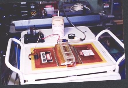
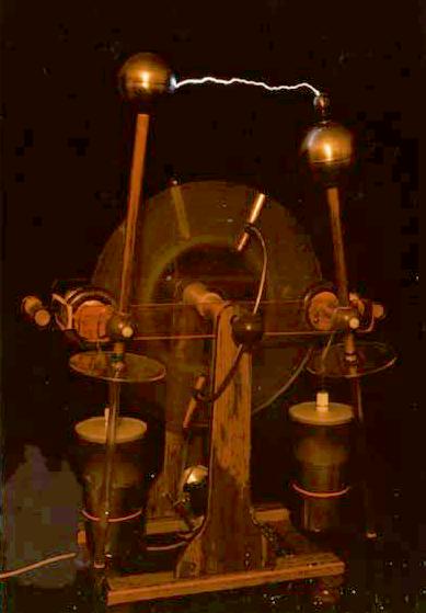
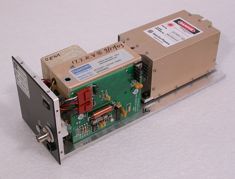
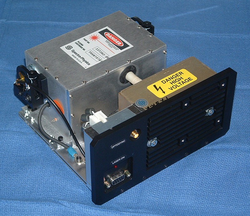
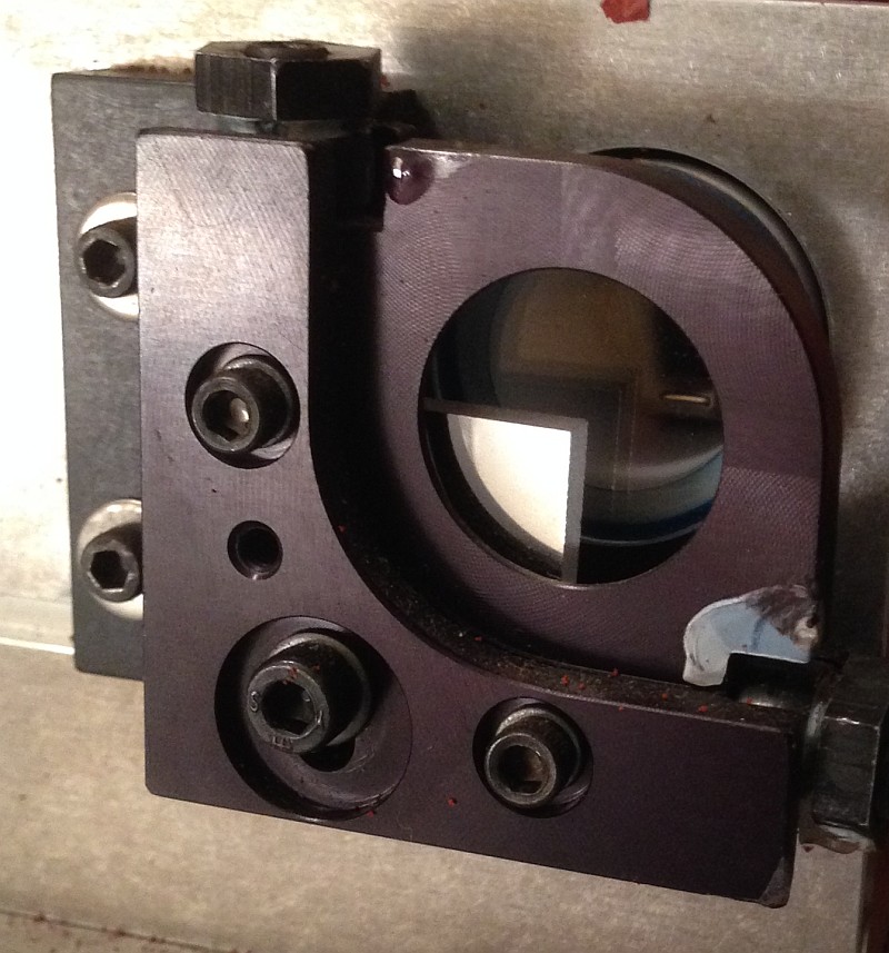