The pulse forming network is what determines the performance of a pulsed solid state laser. Thus, there is a great deal of flexibility in the design of the capacitor charger and trigger circuits. Systems designed for other applications can often be adapted for solid state laser power supplies. See the chapter: SS Laser Power Supplies for more information. And the schematics in this chapter can be easily modified for larger, smaller, or different types of solid state lasers.
WARNING: All of these systems are potentially lethal - some just more lethal than others. Hey, but when you're dead, it probably doesn't matter how well done you are. Before even thinking about building or going near one of these systems, make sure you have thoroughly read, understand, and follow the laser and electrical safety guideline provided elsewhere in this document!
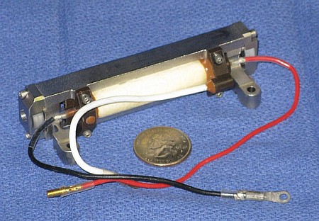
The original application for PFN1 was most likely to be used with the SSY1 laser head (see the section: A Small Nd:YAG Laser - SSY1). The maximum useful energy into the flashlamp is around 14 to 15 J when charged to just over 900 V. Pulse Forming Network 1 shows the assembly with major components labeled. This unit is/was available from Meredith Instruments.
When used without modification, the combination of the 36 uF capacitor and 0.03 mH inductor will result in a 50 to 100 us pulse duration (dependent on other circuit parameters, probably closer to 100 us in practice). This is quite well matched to a Nd:YAG rod. With a well designed cavity, 15 J should be enough to threshold a 50 mm x 4 mm Nd:YAG rod (which is what it apparently was intended to pump) and considerably more than enough for a 25 mm rod.
Note that the capacitor in PFN1 is a very high quality non-electrolytic type. It may be a Polyester film capacitor with an ESR (Equivalent Series Resistance) of around 0.02 Ohm (compared to almost 1 Ohm for a combination of electrolytic photoflash caps with the same uF and V ratings). The extremely low ESR is essential to achieve the required short pulse duration at reasonable efficiency (i.e., maximizing energy transfer to the flashlamp) or at all.
Should you desire to disassemble PFN1 to remount the components in your very own more aesthetically pleasing housing, here is the procedure:
(From Chris Chagaris (pyro@grolen.com).)
This power supply does sound right on the money for a small military Nd:YAG laser, as used in rangefinding, target designators, or illuminators. Typically these lasers are designed to run off of batteries or on-board DC power lines. Typical pulse repetition rates for these systems are on the order of 10 pps and power to charge the cap is usually provided by a DC-to-AC converter, step-up transformer, HV rectifier, PFN, and a parallel trigger circuit. Another much used military PSU operates on the principle of a flyback DC-AC converter.
Your calculations as to the pulse width of the lamp sound just about right. With Nd:YAG's fluorescent lifetime being 230 us, this pulse width would make perfect sense for maximum energy transfer.
The automatic bleeder circuit is something that really should be kept intact even if the useless wiring and that pot are removed. The normally closed contacts of the vacuum relay connect a 10K ohm resistor across the energy storage capacitor whenever the relay's coil loses power. The capacitor will be fully discharged in a couple of seconds. This is an important safety feature!
(From: Richard.)
A diagram of both PFN1 and TRG1 is available in PDF format: (Parts designations for PFN1 may differ from the schematic, above.)
(From: Sam.)
The actual input to the trigger circuit is a bit strange. In fact, I went and checked the actual PCB to make sure the diagram was accurate.
It would seem that you have to apply a high level to the Logic Trigger input to charge C3 (through D3) and then pull it to ground. C3 then powers the circuit long enough to turn the SCR on. A normal TTL signal may be satisfactory. If you're just going to trigger it manually, then start with a 5 or 6 VDC power supply or a battery and see if that works. It may take more voltage.
I used components from Pulse Forming Network 1 and added a line powered capacitor charger and push button operated trigger circuit. A better than 1 pps repetition rate is possible (and considerably more if R1 were reduced in size). Current, the components are sort of strewn all over my workbench - which I definitely don't recommend for safety reasons. Eventually, it will be built into a proper case.
The capacitor charger consists of a 700 VRMS output power transformer, a relic of the vacuum tube age though brand new in its original box. :) I used the low voltage outputs (the 5 V and 6.3 V filament windings, not shown on the schematics) anti-phase in series with the line to slightly drop the the output to about 650 VRMS resulting in just over 900 VDC maximum after rectification and filtering by the main energy storage capacitor (C1). A 300K ohm bleeder resistance discharges C1 in about 30 seconds. The original PFN1 had a relay activated fast discharge circuit using a 10K resistor. Whenever it was de-energized, the resistor was placed directly across C1 discharging it in less than a second. I highly recommend using this if possible.
Unless you have a similar transformer to that Stancor laying around, I'd suggest trying to use something more modern. I doubt you could even buy it today and even if you could, the cost would be ridiculous. One option might be a 230 VAC transformer and a tripler made from 3 diodes (1 kV, e.g., 1N4007) and 2 electrolytic caps (450 to 500 V, probably around 10 uF). This would produce an output that is around 900 V peak. Or, a small dual primary, dual secondary isolation transformer wired to produce 345 VAC (three windings in series) followed by a voltage doubler (2 diodes, 2 capacitors as above).
The trigger circuit consists of a tap off of the bleeder resistance at the 1/3rd voltage point (so about 300 V when the power supply is operating at 900 V output). This charges a .05 uF capacitor which is dumped into the trigger transformer (type unknown - looks like a large photoflash variety) when the push button switch (S2) is depressed. It's possible that one of the tiny units from a disposable pocket camera won't work reliably as drawn. However, you can adjust the size of the trigger cap and/or trigger cap charging voltage to optimize performance for the trigger transformer of your choice. The use of a piezo barbeque igniter is also a good solution if you don't need something fired electrically. :)
I have installed SG-SP1 in a handy aluminum case with a connector to permit any small flashlamp pumped laser head to be easily attached. It may be used as described above or as a general purpose capacitor charger for higher energy PFNs.
WARNING: The AC line input and the energy stored in the PFN can be lethal. An interlock should be included (not shown) to remove input power and bleed off the charge on the energy storage capacitor should the case be opened.
CAUTION: Although the capacitor in the PFN that comes with SSY1 is rated for around 35 uF at 900 VDC, running at this energy may destroy the Q-switch dye cell and possibly the AR coating on the YAG rod adjacent to it after not too many shots. Some samples may survive almost indefinitely but others could succumb in less than 100 shots. I would recommend limiting the voltage for repetitive use to 700 or at most 750 VDC.
(Recall that the SSY1 flashlamp is about 5 mm OD, 3 mm ID, with an arc length of 35 mm. Using PFN1 in SG-SP1, the maximum input energy from SG-SP1 is about 15 J in about 100 us.)
(From: Don Klipstein (Don@donklipstein.com).)
Explosion energy for 100 us is about 1.1 joules times arc length in mm times bore diameter in mm for quartz. EG&G recommends 30 percent of this for good repeated use of quartz (mere thousands of flashes) so I recommend 15 percent of the explosion energy if it is glass.
For a length of 35 mm and a bore of 3 mm, explosion energy would then be 115.5 joules. 15 percent of this is not much more than the 15 joules you're using now.
The capacitance and inductance and voltage (36 uF, 30 uH, 900 volts) sounds about right for this flashtube and flash duration.
If you want to push things, for one thing I would increase the flash duration accordingly. Explosion energy increases with the square root of flash duration. For flashes this short, you get that increase with glass as well as quartz. (This rule holds with quartz to a flash duration up to 10 milliseconds; glass levels off much sooner!)
If you want to push that flashtube, just increase the capacitance and the inductance accordingly. You can probably get away with doubling the capacitance, but that is pushing things.
If you ruin that tube, then I recommend getting a real flashtube from EG&G Electro-Optics Division, which will sell to small time consultants and probably even obvious hobbyists and the like. But they cost about $300 or something like that. But they're quartz and xenon pressure is known (450 Torr unless otherwise specified) and you can get just about any length and diameter almost off-the-shelf. Their catalog items are actually semi-custom parts.
Their catalog has 2/4 and 3/5 mm. (bore/OD) tubes in 1, 2, and 3 inch arc lengths. They also have 4 mm bore 6 mm OD tubes in 2, 3, and 4 inch arc lengths. And all sorts of bigger tubes. One of these should do a good job of increasing the danger of your YAG laser. You probably want the ones designated "low power air cooled".
SG-SP4 still includes the basic PFN1 and trigger output and can drive SSY1 and similar laser heads directly. However, it can also be used as a general purpose capacitor charger for laser heads requiring greater energy input (at up to 900 V).
Before you lament the difficulty in winding the inverter transformer, the design found in the section: Simple Inverter Capacitor Charger Based on HSS1 requires a transformer with a grand total of 32 turns of wire! That circuit can be substituted here for the lazy at heart. :)
Like SG-SP1, it uses PFN1 as the pulse forming network. A bleeder relay (K1) has been added since the values of the resistors in the original voltage divider circuit (R2 to R4) have been increased with a corresponding increase in discharge time to a value too long for safety. K1 will discharge the main energy storage capacitor in about 5 seconds when power is removed.
As shown, SG-SI1 may be powered by a 12 V battery pack and mates directly with the SSY1 laser head. The voltage to which the energy storage capacitor gets charged may be adjusted between near 0 and around 900 V. SSY1 will require a minimum of about 650 V to reach threshold. However, SG-SI1 can easily be adapted for a lower or higher input voltage and/or for other small solid state pulsed lasers, photoflash units, or xenon strobes.
The turns ratio of T1 has been selected so that the voltage on C1 tops off at 900 to 950 V with a 12 VDC input. This is safe for the PFN1 even if the voltage comparator circuit fails to disable the 555 oscillator circuit. As additional protection (especially if your particular PFN has a lower voltage rating for C1), one option would be a string of high voltage zeners (total value selected for your PFN) and current limiting resistor attached to C1 feeding a transistor or SCR to kill input power and set a fault indicator should the normal voltage limiting fail to function for any reason. Increasing the turns ratio of T1 modestly might reduce charge time but then it is even more critical to provide some redundant protection so that the voltage is prevented from climbing above the max voltage rating of C1.
WARNING: Although SG-SI1 is powered by a low voltage source, the energy stored in the PFN can still be lethal. An interlock should be included (not shown) to remove input power and bleed off the charge on the energy storage capacitor should the case be opened.
Note: The inverter portion of SG-SI1 has not been tested.
WARNING: Although SG-SI1 is powered by a low voltage source, the energy stored in the PFN can still be lethal. An interlock should be included (not shown) to remove input power and bleed off the charge on the energy storage capacitor should the case be opened.
I would also recommend adding a fail-safe means of limiting the output voltage on the energy storage capacitor should the feedback circuitry fail for some reason. One simple approach is to have a string of 11 NE2H neon lamps in series with a current limiting resistor across the capacitor. The lamps will turn on at just under 1 KV and provide a load for the inverter reducing the voltage to a safe value until the power input can be removed. (A HeNe laser tube will NOT work in place of the neon lamps as it has a very high starting voltage requirement compared to what is safe for this circuit.)
The unit I used was a Laser Drive model 103-23 HeNe laser power supply brick from an Orion barcode scanner. It runs on 21-31 VDC at under 0.5 A and outputs a constant 3.5 mA from less than 1 kV to about 2 kV and includes a logic input that needs to be grounded to turn the supply on. A HV zener diode and a pair of transistors were added so that the output on the energy storage could be limited to a value between about 500 and 900 VDC (using the component values shown in the schematic). This particular power supply has enough hysteresis in the logic input so that no additional circuitry is needed to provide clean on-off of the power supply's inverter. The voltage climbs linearly to the set value with the power supply turning on every few seconds for an instant to keep it there. With the 3.3 mA output, cycle time for 900 V on the 36 uF energy storage capacitor is about 10 seconds. A HeNe laser power supply that can deliver 6.5 mA would cut this in half.
CAUTION: Since this application is running the HeNe laser power supply in a non-standard way, there are no guarantees about reliability or life expectancy with repeated pulsing via the feedback circuit. It may also have some problems if the series resistors (R1-R3) aren't selected to put the min-max voltage it sees on its output safely within its voltage compliance range. The 103-23 hesitates a bit when starting from 0 V, possibly sensing (incorrectly) a short circuit condition but seems to be happy enough otherwise. However, some HeNe laser power supplies simply won't start into a resistive load at 0 V.
WARNING: Although SG-SH1 is powered by a low voltage source, the energy stored in the PFN can still be lethal. An interlock should be included (not shown) to remove input power and bleed off the charge on the energy storage capacitor should the case be opened.
I would also recommend adding a fail-safe means of limiting the output voltage on the energy storage capacitor should the feedback circuitry fail for some reason. One simple approach is to have a string of 11 NE2H neon lamps in series with a 25K 2 W resistor across the capacitor. The lamps will turn on at just under 1 KV and provide a load for the inverter reducing the voltage to a safe value until the power input can be removed. (A HeNe laser tube will NOT work in place of the neon lamps as it has a very high starting voltage requirement compared to what is safe for this circuit.)
Here is a schematic for a high power xenon strobe unit suitable for pumping a medium to large ruby, Nd:YAG, or Nd:Glass laser rod. (However, this would still be considered small compared to those at the Laser Fusion Facilities of the Lawrence Livermore National Laboratory.)
WARNING: This is only an example. We take no responsibility for either the accuracy or functional correctness of the schematic or any consequences should you attempt to construct this circuit either in its original form or modified in any way.
                                                        L1
     Power         D1   R5                            ::::::
         +-----+--|>|--/\/\--+-----+------------------^^^^^^----------------+
      ||(      |  5kV   5K   |     |                25 uH (est)             |
      ||(      | .5A   25W +_|_    /                                        |
H --+ ||(      |            ___ C1 \ R1  C1-C4: Energy storage              |
     )||( 600  |           - |     /     capacitor bank,          Flashlamp |
 115 )||( VRMS |             |     |     3600uF, 450V (each!)           FL1 |
 VAC )||( 200  |             +-----+                                       +|
 2A  )||( mA   |             |     |     R1-R4: Voltage drop               _|_
     )||(      |           +_|_    /     equalizing resistors,            | | |
N --+ ||(      |            ___ C2 \ R2  200K, 1W                Trigger ||   |
      ||(      |           - |     /                              30kV   ||   |
      ||(      |             |     |   R7               + C5 -        +--||   |
         +-------------------+-----+--/\/\--+-------+-----||---+   ::(   ||   |
      T1       |             |     |  1.8M  |       |   3.9uF  |   ::(   || _ |
               |           +_|_    /    1W  |       |   450V   |   ::(    |_|_|
               |            ___ C3 \ R3     |       |          |   ::(      |
               |           - |     /        \       |          +-+ ::(     -|
               |             |     |        / R8  __|__ SCR1      )::(      |
               |             +-----+        \ 1M  _\_/_ C107D     )::(      |
               |             |     |        /     / |   400V      )::(      |
               |           +_|_    /        |    |  |   4A        )::(      |
               |            ___ C4 \ R4     |    |  |          +-+    +-+   |
               |           - |     /        |    |  |          |   T2   |   |
               |  D2    R6   |     |        |    |  |          |        |   |
               +--|<|--/\/\--+-----+--------+-------+-----+----+--------+---+
                  5kV   5K                  R9   |   R10  |
                 .5A   25W         Fire o--/\/\--+--/\/\--+
                                   (+5)     100      100
Even a properly specified flashlamp may explode and must be operated behind protective shielding or as in the case of a typical laser, fully enclosed in the cavity reflector. Flashlamp cooling must be adequate for desired cycle time.
        |                         |           |
     ---+--- are connected;    ---|--- and ------- are NOT connected.
        |                         |           |
CAUTION: Although this should be operating the flashlamp within spec when run at low duty cycle, it is still what's known as "pushing the envelope". Use at your own discretion.
The capacitor charger consists of a 650 VRMS output power transformer driven by a Variac to provide up to about 450 VDC from a full wave rectifier. The transformer I used is extremely overrated current-wise. A smaller one could be used since the cycle time is so long and the average power requirement is only about 10 W.
A couple of alternatives are also shown in the schematic:
The capacitor bank is a pair of 1,800 uF, 450 V, electrolytics (never used but quite old Mallary "computer grade" units in my implementation). CAUTION: Some means should be provided to prevent the voltage from exceeding the 450 V ratings of C1 and C2. While electrolytic capacitors generally have some safety margin, it is best to obey the rules. Depending on your actual line voltage, the charging schemes described above may be operating close to the edge when set for maximum energy. :)
The trigger circuit is basically the same one used in SG-SP1 (except for part numbers) but since the maximum voltage is lower, it operates from 2/3rds of the capacitor voltage instead of 1/3rd.
D3 and D4 are reverse protection diodes for the capacitor bank (C1,C2) and flashlamp (FL1), respectively. They need to have a voltage rating of at least 500 V and a peak current rating of several hundred amps. However, the continuous current and power ratings can be small since the duty cycle is very low - or zero. I don't know if either of these diodes would ever conduct under normal conditions as the circuit is not likely to be underdamped. I would suggest a 600 to 1,000 V plastic cased diode with a 200 A or greater IFSM rating. They don't need to be fast recovery or other special types. Or, leave them out and measure the residual voltage on C1/C2 and FL1 after a trial shot - if they are both positive, the diodes aren't needed.
The panel meter is calibrated to read 500 V full scale. Of course, it would be really cool to have it display energy in joules. This would make a nice little project in itself. An A/D to monitor the capacitor voltage along with a PIC or other single chip microprocessor, or maybe just an EPROM or Flash based lookup table could do the conversion. Or, even simpler, an analog multiplier configured to square and scale the voltage. :)
A relay connects a high power bleeder resistor to the capacitor bus when power is removed or switched off, the case is opened, or the neighborhood experiences a blackout due to the use of this device) and the capacitor bank is thus automatically discharged. However, even with the relatively low ohm resistor, reaching a safe level still takes 10 seconds or so. A 'Live' indicator lamp (IL2) shows when the voltage on the caps is above about 100 V.
Cycle time is limited by the average power rating of the flashlamp.
WARNING: The AC line input and the energy stored in the PFN can be lethal - especially the energy stored in the capacitor bank! In fact, conservatively, there are enough joules there at maximum voltage (360 J) to kill dead-dead, six large adult humans simultaneously with the power off! Take extreme care and don't assume anything!
With the long pulse duration and relatively high ESR of the electrolytic capacitors, performance won't be as great as with a high quality capacitor. However, it should be quite adequate for basic testing. In fact, the inset photo in SSY1 Laser Head Assembly (photo courtesy of Chad Anderson) was made with just such a setup using a 200 uF, 450 V Rubicon capacitor, charged to around 450 V by a DC to DC converter, and home-built trigger circuit.
HSS1 consists of the inverter, pulse forming network, and trigger circuit.
One beauty of this inverter design is the super simple transformer requiring a grand total of 32 turns of wire. Yes, you read correctly, not the hundreds or thousands of turns you might have expected! :) I didn't believe it the first time I saw the transformer description either. It takes advantage of the flyback pulse generated when the chopper IGBT turns off boosted by the 1:1 autotransformer.
The inverter consists of a CMOS TLC555 timer and IGBT (Insulated Gate Bipolar Transistor). The IGBT is driven like a MOSFET but has output characteristics more like that of a bipolar transistor - the best of both worlds. The output voltage is monitored by one section of an LM339 quad voltage comparator and shuts off the oscillator once full charge is reached. With the components values for the voltage divider resistors (R14,R15,R17,R18) shown, this is approximately 900 V. The circuit should work for voltages up to 1 kV or more by changing the value of the parallel combination of R17||R18. As the voltage decays due to leakage through the trigger circuit and voltage monitor, the oscillator will come on briefly at periodic intervals to top off the charge. With some minor changes, the idling current could be substantially reduced.
The other sections of the LM339 are wired as buffers to accept an inverter ENABLE signal, provide a (low going) READY output signal, and drive a READY LED. The ENABLE input and READY output allow the control logic to turn on the inverter on demand (which is fine for the intended application). (But the internal voltage limiter cannot be overridden.) This reduces the idle current consumption substantially.
The trigger circuit consists of an opto-triac driving a 10 A SCR which dumps a 0.082 uF capacitor charged to about 300 V through the trigger transformer. For manual triggering, these components could be replaced with a pushbutton switch.
The PFN (Pulse Forming Network) as shown was designed to optimally drive a 8358 flashlamp with a 15 J input at less than 50 us. The inverter itself really doesn't care what is used for the PFN except that as designed it charges to 900 V and how long it will take to charge the energy storage capacitor. This one was designed based on a Ko value for the flashlamp of around 12. For the SSY1, use the PFN as specified in the other SSY1 power supply schematics or modify appropriately for your specific flashlamp and pulse width requirements.
Gapped versions of this core may be available. If both halves are gapped, specify 0.2 mm. If you get a gapped piece paired with an ungapped piece then the gapped one should be 0.4 mm.
The primary and secondary are each 16 turns of insulated #20 AWG hookup wire, but wire size is not critical and the secondary could easily be #22. Magnet wire is fine with adequate insulation between layers and between the secondary and the core (3C8 and related ferrite materials are slightly conductive!), and as thick as #18 should easily fit.
Photos and descriptions of Wes's ruby laser assembly and WE-SP1 (as well as of similar units and other home-built power supplies) may be found in the Laser Equipment Gallery under: "Hughes Rangefinder and Home-Built Ruby Lasers".
Note that Wes was never able to get the laser to lase using his first Q-switch driver and original resonant OC. However, by replacing that OC with one from another ruby laser and aligning and locking down the Q-switch prism, the laser fired successfully without using the Q-switch. I suspect that the inability to make it work with the Q-switch was at least partially due to the excessively long discharge pulse (I estimate at 6 ms) which results in insufficient population density in the upper energy state of the ruby for the laser to reach threshold when the Q-switch is in position. Or, perhaps, the alignment was never quite perfect.
Information on aligning the ruby laser optics and Q-switch can be found in the sections starting with: Aligning the Hughes Ruby Laser.
Note: I have changed some of the part numbers so that they are unique (and hopefully corrected some of the minor errors/duplications in the process). The trigger circuit can be found in the next section. The part numbers for D3 and D4 have been swapped compared to the original drawing as it has been pointed out that the device number for D3, NTE504, must be an error. The NTE504 has a peak surge current rating of only 1.5 A. The current through the flashlamp will be in the *hundreds* of amps. So, the first shot would blow that diode to bits. So, I assume the original labeling to be a typo since the NTE542 has a peak surge current rating of 200 A and the diode for the trigger circuit doesn't require a high current rating. The NTE548 which has a 250 A surge current rating might also be adequate but a part with an even higher rating would be better.
The energy storage capacitor value will be 4 x 3,600 uF at 350 V in series with charge equalizing resistors for a net value of 875 uF derated to 1,350 V max. Why these capacitors? Because I got a good deal on eBay!
SG-SG5 will probably be similar to WE-SP1 with the SG-ST1 Q-switch controller. The flashlamp energy will be adjustable, probably with some type of regulation to assure pulse-to-pulse consistency.
Here is a possible set of switches and controls for running the laser:
With the long fluorescence lifetime of ruby - about 3 ms - timing of the Q-switch is not as critical as it is for Nd:YAG with its much shorter fluorescence lifetime (230 us). The Q-switch motor spins at 30,000 rpm or 500 rps for a period of 2 ms. So, if the flash duration is resaonably short compared to 2 ms, there will be a high probability of a decent output energy even if the flashlamp was triggered at random relative to the Q-switch position! Even if the flash duration is as long as 3 ms, half the time, more than 50 percent of the available energy will have been transferred to the rod when the Q-switch is triggered. This is probably the main reason that faulty Q-switch trigger circuits seemed to produce successful results, though I bet the variation in energy due to the timing not always being optimal remained a mystery and was probably attributed to other causes. However, with a proper design, the pulse energy should be quite consistent.
The diagram is available in PDF format:
SG-ST1 consists of several parts:
To obtain a continuous stream of properly timed output pulses, WITH THE HIGH VOLTAGE OFF!, jumper the output of the 555 (pin 3) to TRGIN-H with External Trigger Input selected. (CAUTION: Selecting Internal Trigger Input would short out this signal!) TRGOUT-H will then be a squarewave at one half the Q-switch motor rotation rate where the rising edges coincide with the SCR trigger point.
The advantage of using 555 timers is their low cost and availability even from Radio Shack. TTL or CMOS monostables (one-shots) could be substituted with a slight reduction in parts count.
Note that this circuit will only work where a delay is expected between the pulse from the magnetic sensor and the firing of the flashlamp. As originally adjusted, there is expected to be 0 delay for clockwise rotation of the Q-switch prism. Ways around this are either to run the motor in reverse and delay almost the entire rotation period (but without a PLL or other means of speed stabilization, this may result in too much variability in timing due to the long delay required) or to reposition the Q-switch assembly by loosening the mounting screws (requiring optical alignment.) See the section: Notes on the Q-Switch for details.
The circuit shown in Q-Switch Synchronizer and Firing Circuit for M-60 Rangefinder Ruby Laser and described below is a simple and complete solution that can be used to run it with the addition of a 1,200 V power supply. The only specialized components are the saturable core trigger transformer, which can be easily wound by hand.
When I purchased the laser, it still had its stock flash tube, the FX-103C-3 but was missing the collimator. I use a bank of 12 low ESR electrolytics (Marcon 400 V, 470 uF) to give me a 660 uF, 1200 V capacitor bank. When firing the tube, be sure to use at least 1,000 V across the capacitor bank, this seems to be the lasing threshold for this arrangement.
The synchronizer uses the common CD4528 CMOS dual monostable chip. One of the monostables in the chip is used as the delay element, and the other provides a signal to fire the flashlamp, via the opto-isolator. It is a very simple circuit, but it is very reliable, and will not fire the lamp unless the fire button is pressed. I would also recommend an interlock switch between the opto-isolator LED and the 4528, as a further safety precaution. The circuit around the CS549 is a rectifier and buffer for the sensor, (and also simple inverter) to trigger the delay monostable. Pressing the fire switch activates the monostables by pulling the clear pins high and the first pulse received from the sensor sets the delay running. This delay is set by R3, the 10 turn 200 K variable resistor. When the first monostable delay finishes, the high-to-low transition is sent to the inverting input of the trigger shot monostable, which then pulses the opto-isolator for a short time, and thus triggers the SCR. This discharges the 0.1uF cap into the series injection transformer, and triggers the flashlamp.
The series injection trigger transformer/PFN is reasonably important, so here is a basic description of how the design was coined. I was after about 8-10KV for the flashlamp to trigger, and also a fast-rising pulse. I calculated 24 x 350 V = 8,400 V should be enough turns. I used litz wire because it was lying around, and had a 2 KV insulation but it probably wouldn't do any harm to use normal, well insulated, copper wire either. The core used was a Siemens RM-14 core of N-87 ferrite material. I first wound 24 turns of the litz wire onto the centre of the core, it came to 2 layers, between which I insulated with capton tape. A single turn was then wound over the top of this coil, which was made of 4 sections of litz wire laid flat and soldered together. This was further insulated with capton tape. The core was assembled over the windings without any air gap, so as to saturate quickly when the lamp fired. An additional inductor may also be used in series with the lamp as part of the PFN if you want to try and further tune the pulse shape for the flashlamp (I didn't find that an inductor was required, though). If you find that the lamp doesn't trigger, swap the wires going into the single turn around.
To tune the synchroniser, put an LED in place of the opto-isolator input, and short the 330 ohm series resistor (this will yield a brighter flash from the LED). The motor is spun up with 12 to 15 VDC. This gives about 24,000 RPM, or 420 us/rotation. In a darkened room, bring the LED close to the top of the prism (VERY CAREFULLY SO AS NOT TO HIT THE SPINNING PRISM - THIS CAN DAMAGE THE OPTICS). The triangular glass surface of the prism perpendicular to the motor shaft has been ground, and gives a good surface to shine the LED and look at when adjusting the delay. When the firing switch is pressed and held down, with the LED close to the prism, the prism appears to freeze and I then turned the 200K tuning pot (see schematic) until the prism was frozen about 5 degrees before the resonator would align, to allow for the flashlamp trigger delay, and also for the offset required for the Q-switch to do its Q-switching. I then put the opto back into the circuit and charged the capacitors to 1,050 V. I spun up the motor with 15V, and hit the fire button. A piece of blue paper was the target. It worked first time, discolouring the paper, but it was not very powerful. To further tune it, I kept charging the supply and firing it, while adjusting the 10 turn delay tuning pot between shots. It took about 8 shots to tune it as well as I could. I have to admit that it seems to be putting out two beams for some reason, when it it was tuned well, but I think that this is because I removed the output coupler early on (very dumb thing to do) before managing to get the laser working. It still lases well though.
Less than a dozen small electronic components need to be added to the original circuit (I placed most of them on a 1 square inch mezzanine board) and the thin chrome plated aluminum flashlamp reflector can easily be reformed to enclose the Nd:YAG rod providing for very efficient energy transfer. Thus, the entire uYAG laser can be constructed in a case less than 1/4 the volume of the original MAX camera!
Depending on the design of the cavity optics, less than 5 joules should be sufficient to threshold a YAG rod of this size (1/8th the volume of SSY1). Therefore, depending on your objectives, it may be possible to substitute a smaller energy stroage capacitor resulting in longer battery life and shorter cycle time. Alternatively, for maximum output pulse energy, using a higher quality (non-electrolytic) energy storage capacitor and pulse forming inductor may be desirable. However, I'll leave it up to you to determine the explosion energy and thus safe range of operating energies and pulse durations. See the other chapters on SS lasers.
Circuitry was added to control the 1.5 V to 300 V inverter, sense when the capacitor is fully charged, and fire the flashlamp. The circuit changes were designed to take advantage of the way the MAX operated as part of the camera and to minimize rework to its printed circuit board. Where a new board is to be fabbed, the latter is not an issue but it turned out that this approach was still more-or-less optimal.
Here are descriptions of the control and status signals:
See Modified MAX Flash Unit Schematic when reading the following discussion.
Operation of the OPR signal for RUN and CRUISE is analogous to the original charge push-button of the MAX camera: A TTL high is the same as pressing the button while OPEN is like releasing the button. The addition of a diode (D8) allows a solid TTL low or ground to such enough current out of the drive circuit to kill inverter oscillation.
The OFF signal drives the base of Q5 which similarly shorts out the drive to stop oscillation.
The FIRE signal is capacitively coupled to the gate of the triac, Q6, to discharge the trigger capacitor, C3. This is exactly analogous to the way the original shutter contacts worked.
An additional circuit, very similar to that of the 300 V limiter, was added for the READY status signal. Its input is derived from the energy storage capacitor through the same high voltage neon bulb (IL1) and zener (ZD2) so it turns on at around 300 V. It was found necessary to add a sneak path prevention diode, D9, to block voltage making its way in from the TTL supply and restarting the inverter even if OPR was open.
While for the most part, this power supply will get the job done, it is overly complex. At the very least, a more rational choice of components would result in a much cleaner more reliable design. However, there is at least one problem: If the power transformer in the capacitor charger is really rated at 1,200 VRMS, applying full line voltage to it would result in excessive voltage on the capacitor bank. Thus, a Variac or other means reducing its output voltage or some other modifications would be needed to prevent fireworks.
A suitable power supply for the Hughes ruby laser (or a similar one) using a proven design can be built that is both simpler and includes a driver for the Hughes ruby laser Q-switch as well as additional safety features. See the section: Wes's Ruby Laser Power Supply (WE-SP1).
Of course, if you (or the guy who designed this) had a stock of 220 uF, 400 V caps left over from another project, sure, go for it! In conjunction with typical electrolytic caps, the 120 uH inductor would result in a pulse duration of about 750 us which should be safe for the FX-103C-3 (or equivalent) flashlamp.
And, I hope you like to do lots of soldering!