(From: heru_kuti@yahoo.com.)
Two words VERY GENTLY!!!!! The best way to clean laser optical surfaces is not to dirty them. If you inevitably get it dusty blow it off with compressed dry air. If some dirt remains it is best to clean with a piece of REAL lens tissue and very pure acetone being very gentle on it. If you get it badly dirty, like as if some yahoo from the machine shop touched it before washing his hands, the only course is to really wash it. To do this, first dust off as much as you can, next rinse in warm clean water. follow up by washing with a cotton ball and warm detergent/water solution. (Clean water with CLEAR dish soap works well.) Finally rinse with distilled water followed by pure acetone.
(From: Klaus Dupre (dupre@fee-io.de).)
Sometimes the rod holders are fixed with epoxy glue or other glues. Than you may have problems removing the holders without damaging the rod and/or the holders. You may chip the ends and thus require regrinding, polishing and coating.
There are two methods to remove the glue:
(From: Elliot Burke (elliot@nonamehitide.com).)
Before using aggressive means to undo an Epoxy bond, you might try methyl bromide. This is available as "Milsolve" from Summers Laboratories. It dissolves Epoxy. If you use this stuff, be sure to obtain and read the MSDS. Methyl bromide is much more aggressive than methylene chloride on Epoxy.
Good practice for use of solvents is to soak things in them in a covered container. Rags with solvent in them should be disposed of carefully. At least bag them before they releast all the solvent into your local air. I leave a few windows open.
(From: Josh Halpern (vze23qvd@mail.verizon.net).)
Believe it or not many Epoxys can be "rotted off" if left overnight in methanol, which is somewhat safer to use than methylene chloride.
Where there are adjustments, the wide bore, planar mirrors, and high gain of the typical solid state laser make alignment quite straightforward for once. :) The same basic principles apply as with HeNe and Ar/Kr ion laser alignment (see the sections starting with: External Mirror Laser Cleaning and Alignment Techniques for details) but due to the orders of magnitude more gain, you only need to get close for the system to start lasing. Disks with small holes will be useful to center the alignment beam in the cavity and for IR emitting lasers (like YAG at 1,064 nm), some means of detecting the beam such as an IR sensitive camera and Zapit paper will be needed. Once the cavity is roughly aligned, the Q-switch (if present) is installed and aligned to the beam path. This can still take a long time - hours - especially if you haven't done it before.
Note that Zapit paper is great for this but there are many common materials that will behave similarly including common packaging (anything with dark ink on a light colored cardboard base). Even 5-1/4" diskettes (either the envelope or the diskette itself) can be pressed into service. Now you have a use for those cartons of antiquated storage media. Other magnetic media like data and video tape may also work because they consist of a very thin dark layer on a clear base material. Don't toss those crinkled VHS tapes! :)
The following applies to a typical medium-to-large ruby or YAG Q-switched pulsed laser:
(From: Chris C.)
Typically to align a laser, you set up a reference beam from a HeNe laser through the cavity. With a solid state laser, you may want to ensure the rod is centered on the high reflector and output coupler optics. Then with the OC removed, align the HR to aim the HeNe back into itself. The same is done with the OC.
With a Q-switch (Q-sw), the situation is complicated. What might be advisable if the assembly is simple enough, is to remove the Q-sw from the cavity and align the laser without it. Than, if it lases, at least you know that there is no optical problem with the rod, HR, or OC. And you may be able to just pop the Q-sw components back in while retaining the non Q-switched cavity alignment. Note, this may not be possible unless you at least align the cavity first with the polarizer, as some translation and perhaps off-axis pointing of the beam will result from it. So that means: align initially without the Pockel's cell and Quarter WavePlate (QWP), but with the polarizer.
It is then a matter of figuring out if there is something wrong with the Q-switch, polarizer, or QWP. (Note that all of this assumes that the Q-sw uses this common topology.)
If the Q-sw optics look OK and are clean, (DO NOT clean them unless you really know how to clean laser optics), then reinstall the Q-sw components. (Also note if the Pockel's cell is filled with liquid. It should be. If it is dry, it is probably no good.) Since the HeNe beam is of a different wavelength from the ruby laser, it may be difficult to verify proper operation of the Q-sw using the HeNe. However, if you have access to a 670nm, 680nm, or ideally a 690nm laser diode, that wavelength would be close enough to the ruby's 694nm to use the diode laser as an alignment reference (assuming you can get a reasonably circular and collimated beam). Then you can align the polarizer to Brewster's angle by orienting the polarization of the ref. beam for a P-bounce off the polarizer. Adjust the angle of incidence for a minimum reflection. At that point, with the Pockel's cell still out of the cavity, the beam that passes through the polarizer will pass through the QWP, reflect off the HR, bounce back through the 1/4 wave plate, and be reflected out of the cavity by the polarizer. That is because the two passes through the QWP caused a 90 degree polarization rotation, resulting in a S-bounce off the polarizer, which is a high reflectivity incident condition.
Now there are complexities to getting the Pockel's cell aligned that are deeper than what we are into already. But assuming you can get it close, the situation described above should not be altered by its presence. However, if you can arrange to apply a constant voltage to the Pockel's cell that is identical to the voltage applied by the power supply to produce an output pulse, you should find that the reflection off the polarizer (the reflection of light out of the cavity of the beam that has bounced off the HR) no longer appears, or is effectively gone (it will be very faint). So that is the proper operation of the Q-sw: No voltage on the Pockel's cell=strong reflection of light from the polarizer. Voltage on Pockel's cell=minimal reflection off the polarizer.
If you can get this far, there is a good chance you can run in Q-switched mode now.
If you can get some YAG or ruby laser manuals from other lasers with alignment procedures, do so. Of course, the holy grail would be the manual for your laser.
(From: C. Bollig.)
"Oops... it happened. We moved into our new lab space and one of the Quanta-Ray DCR-11 Nd:YAG lasers got bumped."
Realignment from scratch isn't a trivial job if you haven't done it before. It involves removing everything from the optical cavity and subsequently lining components up with the aid of a HeNe laser. If you hare a real budget, letting the laser manufacturer or a reputable laser service company do it may be best since aside from the safety issues, damage to the laser crystals and optics are quite possible if alignment isn't perfect. But, here are some comments and suggestions along with the risks if you want to play:
(From: David Demmer (ddemmer@physics.utoronto.ca).)
And a word of caution here: These DCR's tend to operate pretty close to the limit of what their guts can handle. Operation anywhere near full power with a misaligned cavity is almost guaranteed to blow up some internal component, such as your YAG rod or Pockels cell.
If you attempt this yourself, you must remember to do all the alignment with the laser "free-running", i.e., not Q-switched. Use some diagnostic aid like Zapit(tm) (burn) paper or a CCD camera to look at your beam profile. Don't Q-switch the thing until the beam profile is perfectly symmetric, and therefore well-aligned.
Why do you think we charge so much to setup and tear down a YAG laser. YAGs have external and internal cooling water. The internal water is deionized (distilled, without minerals or salts that cause ions) also called anionic water. Anionic water doesn't conduct electricity, so it CAN come into contact with electrodes and cause no harm. Our system flows water across the pumping lamp, and YAG rod to cool them, then circulates the heat-bearing water across a stainless steel heat exchanger which couples the heat to cold tap water, and dumps the heat-bearing tap water down the drain. Efficient, eh? I want to get a chiller someday.
"I and a colleague tried several things: replacing the flashlamp, tweaking the front and back mirrors, replacing the deionized water in the closed-cycle cooling system, but none of these steps improved the output."(From: Jim Cavera (jcavera@alcnet.com).)
Try checking the crystal. Nd:YAG crystals are prone to heat-induced, microscopic fractures. Enough of these can drop the output energy considerably or even extinguish lasing altogether. CAREFULLY remove the crystal (no dust or oil, please, or even fingerprints, and be particularly careful of the AR coating that most crystal manufacurers add) and put it under a good optical microscope. What you would be looking for are site inclusions and fractures that cut across the axis of the crystal.
NOTE : this is probably the last thing you would want to check. Try everything else first. Nd:YAGs are simple creatures though, and it sounds like you have everything else pretty well covered.
(From: Rick Fletcher (fletcher@news.uidaho.edu).)
Definitely the last thing! Check the cavity condition (corrosion, algae, etc.) before doing this. Also, make sure you do not have a damaged optic, like a quarter waveplate, etc.
(From: Joshua Halpern (jbh@idt.net).)
One of the things that may be wrong is the Q-switch. Turn the laser to long pulse (Q-switch off) and see if you get full power or near. If so the Q-switch is the problem. The easiest thing would be if the Q-switch delay is set incorrectly. It's just a matter of turning a dial.
Next you need to look. First get some exposed Polaroid film and put it in a baggie. Then hold it in front of the laser for one shot. Hopefully you still have enough power to get a burn pattern. This should be symmetric (I forget whether the JK had a near gaussian or a "doughnut" pattern). If you see ugly striations, you either have a very badly adjusted laser or some burns.
You have probably "misaligned" the laser when you tweaked the lamps. YAGs, expecially the oscillators are better tuned for beam shape than pulse power.
Next remove all the beam tubes and look carefully at the mirrors, rod ends, polarizer and Q-switch for burns. TURN THE LASER OFF FIRST.
You probably will need a dentist's mirror and a small flashlight. Maglites are great for this. The best way is to hold the light at a high angle to the perpendicular and look directly at the component, but you may have to move the light and your head to see this.
Then put a piece of white paper behind the laser head and use the flashlight to illuminate it, while looking through the rod with your dental mirror. This should give you a much better idea about what is going on.
The hint about looking at the cavity is also good.
JK was represented in the US by Lumonics, who appear to have gone out of the scientific laser business, but they may know someone who still does servicing (They are in Ottawa, Canada).
Finally there are lots of folks in chemistry and physics at NIST who operate YAGs and can give you some idea of how to proceed.
Note, also, that rods sold in this condition may have failed other preliminary quality tests including not having the proper percentage or uniform doping or being cut from a portion of the original crystal which had optical defects. Presumably, the manufacturer would not have gone to the trouble to cut them (to the rod shape) if they were total garbage but who knows?
The first comments are for ruby and the second for YAG.
(From: Steve Roberts.)
Sadly, ruby is about the second hardest mineral on the planet to polish. Most commercially available abrasives don't even scratch it and you need a optical grade finish or the rod ends will blow off. A less then perfect finish greatly increases the lasing threshold. A flat takes two lapping rigs (one slightly spherical, one slightly concave) made of a material of slightly less hardness then the ruby, and a lot of different sizes of abrasives. You could start at a local lapidary shop and have them saw the ends, but they must be parallel to within 1/2' or so, then try to lap it down following the instructions in an amateur telescope making book.
By the time you go through all this, including buying a optical flat to check the ends and a HeNe laser to measure parallelism, plus practicing on a couple of glass rods, you could buy the whole head from say Meredith or Midwest in working order for less cost. Your other option is to have one of the laser rebuild companies that do ruby and YAG, such as Kentek, repolish it for you.
(From: L. Michael Roberts (NewsMail@laserfx.com).)
I called a friend. He makes YAG optics. I think most are smallish. Here are some notes for YAG in particular:
He said to get a book on polishing YAG in a lapidary store.
I would bet though, that normal lapidary techniques won't yield anything like 1/4 wave optics. Perhaps the addition of keepers to normal lapidary practice would get you into that realm.
(From: Clive Washingtron (clive.washington@astrazeneca.com).)
A section of the jewelry/lapidary community, those who facet gemstones, may be able to do this - and there are several thousand such people worldwide. Some cutters just turn out 'ordinary' stones but a few of us aspire to high optical quality. Do you have any idea of just how flat the end faces need to be? On a quarter inch facet I could easily achieve 3 or 4 rings so perhaps it would be possible!
(From: Sam.)
Yes, I think it may be possible to achieve sufficient flatness to get it to lase, but probably not to achieve the original performance. By "3 or 4 rings" I assume you mean interference fringes where flatness specs are often in 1/10 or 1/20 lambda. However, all that is needed is a stable round trip path in the resonator to get it to lase, but that could still result in a messed up beam and reduced output power. There is also the issue of applying an antireflection or mirror coating to the rod ends.
One purpose of my strong comments is to discourage people who think they can simply buy a cheap unpolished or damaged rod on eBay and all it will take is a few minutes to grind it flat free-hand using 1,200 grit sandpaper and then polish it (also free-hand) with jeweler's rouge! :)
Stock KTP crystals generally have a cross-section of 2x2 or 3x3 mm, though some commercial DPSS lasers use 1x1 mm crystals. The typical maximum beam diameter at the crystal faces is typically less than 200 um, possibly less than 100 um. To minimize diffraction losses, space equal to the beam diameter should be allowed surrounding the beam so a 100 um intracavity beam would require a 300 um area on the crystal. So, if there is a small undamaged area remaining, repair may be possible using the existing KTP with minimal rework.
The main challenges are:
Where the original holder has no adjustments but assumes the beam is in a particular location, it may be necessary to grind down the sides of the crystal so the clear area can be positioned precisely where it is needed. KTP is relative soft and files designed for metal actually appear to work reasonably well. But make sure to protect the very delicate coated ends.
Two part Epoxy or UV cure adhesive can be used to attach the crystal to the holder. Depending on how many degrees of freedom are available for the holder, the orientation of the KTP may be critical, both in terms of rotation about the optical axis of the laser and the angle with respect to the optical axis.
I've successfully remounted the damaged KTP crystals in a couple of DPSS lasers. On one, the KTP crystal was chipped at one end with about half of the face totally missing. The entire mount had to be fabricated from scratch as the previous owner had lost the original parts (though the mount wasn't very good to begin with, which is perhaps why the crystal got damaged). See the section: Reconstruction of an 80 mW Green DPSSFD Laser. The other was a Uniphase SLM uGreen DPSS laser where the 3x3x3 mm KTP crystal had been shattered by threading a screw too deeply into its mount. Only a small area in one corner was still usable. The KTP had to be filed down so the good area could be centered in the beam but the original holder then could be used.
(From: billyfish@aol.com).)
One of my pet peeves in laser specification is the attempt to get maximum energy out instead of maximum peak brightness (radiance). In most cases, although not all, high brightness is preferred over gross energy. Once energy is stored in the rod, there is only a certain amount that can feed into forming a TEMOO mode. As the energy that can support that mode is used up, there is a remainder that can only couple efficiently to higher order modes. The result is more energy, but with more beam divergence and greater pulse width, ore even multiple pulses.
Single mode performance can be achieved by using a dye Q-switch. Optical quality of the system has to be good. Otherwise, you end up with a single mode, but it may be a poorly shaped one.
The dye Q-switch does its magic by keeping gain slightly above threshold for a long time. This gives the lowest order mode a chance to grow at the expense of higher order modes that have lower gain. Finally, when the dye bleaches, that mode grows in energy, excluding off-axis modes.
A similar effect can be achieved using electro-optical Q-switches. Use a two step process where the first step gets you barely above threshold thereby selecting the highest gain mode. The second step reduces resonator losses to where the selected mode seeds the laser to produce a high energy lowest order mode.
How much variation is there?
Please keep in mind that you are going through two nonlinear processes to get to the 4th harmonic. it is the least efficient process of the the other nonlinear processes, and any instability in pulse to pulse power/energy is magnified by the time you get to the 4th harmonic.
The easy way to tell if this is the case would be to have a dual channel oscilloscope look at the fundamental and the 4th harmonic. If you notice dips in the fundamental at the same time as the dips in the harmonic, then that's the problem. If you are seeing very large fluctuations only in the 4th harmonic in this case, it's probably due to improper phase matching. Try adjusting the angle of the crystal (quadrupler) or the temperature.
"There is a 15% power instability when the laser is working CW, single transverse mode and polarized. The crystal is new, and so are the mirrors and polarizer plate. The power level is OK (13 Watts) but stability is terrible. This is so even without the Q-switch and mode-locker acousto-optics modulators in the cavity."I measured the optical power variation of the pump lamp. Its instability is well below 1%, with frequency components of 60 Hz and harmonics, as expected. It is a new EG&G lamp, clean, and properly installed with correct polarization. The problem is not there."
(From: David Demmer (ddemmer@physics.utoronto.ca).)
My best advice: lasers are simple machines so don't panic, approach it systematically and it will work. Finicky: simple and finicky.
There's only going to be three sources of instability: electronic, optical, and mechanical. Rule out the easy ones - get your electronics shop to have a look at the current to the lamps. If it is steady and the lamp is not in backwards you are OK. If the optical and other mounts are steady, you are OK - they almost certainly are, even if they have crummy adjustments they won't go anywhere unless the system is vibrating.
Optical problems. These usually arise in YAG because it has strong thermal lensing and there are always small fluctuations in the cooling water flow. The trick is make sure that the flow is as laminar as possible and that the intracavity beam is centered in the rod and not too large.
Check the flow tubes around the lamp and/or rod: Are they in good condition? no cracks? held firmly in place? Cracks are hard to see when the tubes are wet.
Are the ends of the rod clean? Sometimes leaks around the rod end seals cause mineral deposits on the faces. This is very tough to check properly without disassembling the lamp/rod housing, but here is a quick-and-dirty.
With the lamps off (!!!) shine a flashlight through the rod while looking through it along the laser axis using a small dental mirror. It should look PERFECT, absolutely NO indication that there is something there. ANY flaw, haze, or whatever which is visible under these conditions will kill you.
Is the rod aligned? Make small (1 to 2 mm aperture) alignment apertures that you can place on the cavity mirrors, and align the laser so that the beam is centered on them. Make similar, though smaller (0.5 to 1 mm) apertures that you can place on the "pot", i.e. the assembly that holds the rod. You must make absolutely sure that the beam is centered on the laser rod. The laser may stop lasing with these in place: this would be a good sign, since it should not if the rod really is centered.
If necessary you will need to do a HeNe alignment of the whole works: mirrors and rod. Don't be afraid to move the pot around to align the laser: it is the only way, and with a HeNe you can always recover from any alignment disaster.
If the beam really is centered and there are still problems, try restricting the size of the intracavity beam: it may be "trying" to go multimode and need a bit of help to keep it TEM00. You may need to reduce the power by 20 or 30% to get it stable, but use the largest you can. Also, if the lamps are driving too hard the thermal lens may be just too strong and the cavity may be getting close to an unstable resonator configuration. Try backing off the lamp current. I know of one laser (Coherent Antares) that will actually stop lasing with too much lamp current.
Above all, there is no point in putting in the mode locker etc. until the laser works really well as an unpolarized cw laser.
(From: Roland A. Smith (see@www.lsr.ph.ic.ac.uk).)
We found cooling water fluctuations to have BIG effect on the system. It originally had the mode locker cooled from the flashlamp supply (ugly) and running a separate small cooler on the mode locker helped quite a lot. In addition we added our own control electronics to the existing temp control. We actually stuck a central heating system heater in the main water bath coupled to a programmable differential controller. This adds heat as necessary to keep things more stable. Do you hear the cooling water controller go "thump .... clunk woosh.... wait .... repeat. If so you're going to have problems.
The water circulation to the mode locker is currently removed. We do have this "thump .... clunk woosh...." system. (Very nice sound effect :) ) However, by changing the secondary water pressure I can have it run almost continuously (only woosh). There doesn't seem to be a correlation between the CW Nd:YAG noise (1 kHz range) and the water temperature control system.=
These systems can be a real bitch. Ours now provides useful service as a door stop. :) Believe NOTHING they tell you.
(From: Mattias Pierrou (mp@optics.kth.se).)
Since your laser components are all new, I suggest that you take a look at the flashlamp and/or your power supply. Some time ago we had stability problems with one of our high power lasers (different kind though - Ar+) and we tracked it down to the old, worn power supply.
(From: Ralph Page (Ralph.Page@Prodigy.net).)
Reading these comments brings back some pretty horrifying experiences from my past. I am not sure I saw the original post but all of the suggestions you noted were consistent with my thoughts. I am really suspicious of the water flow within the pump chamber. Is it possible for you to alter the flow rate/pressure of your cooling source? If you have an alternate to the existing water source or you can alter it simply (flow rate pressure, etc.) you may get a hint about minimizing the instability.
With prices as low as $1.00, serious troubleshooting and repair of a cheap red laser pointer probably isn't worth the effort, time, and expense. However, with the average price of a green DPSS laser pointer still over $150, there could be significant motivation if the warranty has run out, is void due to damage or abuse, or never really existed in the first place. :( But, if there is still a useful warranty, I highly recommend that you take advantage of it!
From the Comparison of Red and Green Laser Pointer Complexity, it is quite obvious that there is a lot more "stuff" inside a green pointer, though not all models are quite this complex. However, even the new generation of green pointers using Multiple Crystal Assemblies (MCAs) rather than discrete crystals and optics, still have 2 or 3 times the number of parts and the need for very precise alignment.
Fortunately, the most common problems are probably still external to the DPSS laser module itself. Better hope so - doing anything inside there is at best a royal pain and probably justified only by its educational experience or laser parts salvage value.
The following photos and diagrams apply to the two typical approaches:
The detailed disassembly procedure will depend on the exact model. A combination of screw, press-fit, and glue holding things together is likely. Non-destructive disassembly may not be possible for some components. See the section: Disassembly and Reassembly/Alignment of the Edmunds L54-101 Green DPSS Laser Pointer for the detailed procedure for the L54-101 model and Disassembly and Reassembly/Alignment of an MCA-Based Green DPSS Laser Pointer. Lower cost models will be more along the lines of the second type, but may be even more difficult to disassemble if it's possible at all. And, as regulatory agencies discover the potential dangers of boosting the power of green laser pointers, manufacturers may be required to assure that they can't be disassembled non-destructively!
Here are the most common adjustments/repairs:
If anything actually got inside the DPSS module, or its components are not even partially sealed, repair may be hopeless since any contamination will likely render it totally inoperable and may result in permanent damage even if cleaning can be performed quickly. In any case, total disassembly of all the crystals and optics would be needed. This will necessitate partial or total realignment of the laser diode, crystals, and optics. In the unlikely event that the laser diode is in a hermetically sealed package (not many, if any, models do it this way due to cost), a total cleaning using proper laser mirror cleaning techniques - followed by realignment - may permit the pointer to be salvaged. However, with most or all units using bare laser diodes, any contamination that reaches the laser diode chip may be bad news indeed. In the latter case, very careful cleaning with pure alcohol or acetone may save it but this has to be done before attempting to power the diode - anything on the facet while powered may be terminal. For pointers using composite vanadate/KTP crystals, much less alignment is needed but access to parts will still be a challenge.
Here are possible problem areas for a pointer that is weak or dead and hasn't been run over by a Sherman Tank:
Of course, if not using the pointer for a few days, remove the battery. Leakproof batteries have been known to leak!
Finally, although the typical green pointer is very well constructed with remarkably precise machining and the use of generous amounts of adhesive, they are still susceptible to shock and impact. And, as the technology matures and costs come down, corners may be cut as well.
I was given one unit that was totally dead after falling onto a hard floor (material not known). The pump diode was butt-coupled (almost touching with no relay lens) to what looks like a CASIX DPM0102 composite crystal, which was secured in place with RTV silicone (essentially bathtub caulk). What must have happened is that the inertia of the crystal and mount at the time of the fall caused the crystal to move ever so slightly, impacting the diode and breaking it into two pieces, the larger of which was still attached to the two bonding wires hanging in mid-air.
If not totally ruined by mechanical shock, alignment may be affected resulting in decreased output power and degradation in beam quality.
So, as preventive maintenance, dump the fancy wooden box that so many of these green laser pointers arrive in and use a well padded case instead. In addition, it might be wise to fasten a lanyard to the pointer so it can be attached to a belt and won't fall on the floor when you bend over. Your pointer will thank you. :)
The construction details are shown in Edmund Scientific L54-101 Green DPSS Laser Pointer. This should help make sense of the procedure below.
The L54-101 uses the same DPSS module as the unit disassembled somewhat destructively in the Laser Equipment Gallery (Version 1.74 or higher) under "Dissection of Green Laser Pointer" and probably many other models. See Internal Organs of Green DPSS Laser Pointer for an annotated photo of the major components.
Here is a detailed procedure that should provide access to everything inside with at least the possibility of reassembly, though putting everything back together with any chance of getting back to a working state with good beam quality will require quite a bit of care, determination, and the prolific use of selected four letter words (see below). :) It would probably be a good idea to have the sequence of photos in front of you while embarking on this adventure. A warning to the squeamish: some of these pics are a bit gory and you may want to send any working green pointers you own to another room for the duration. ;) The case and laser diode driver of the L54-101 are different than those shown in the dissection but all the actual DPSS laser parts are absolutely identical.
The first set of steps deals with basic disassembly of the case:
Note: There is no need to actually remove the driver board if you aren't going to go inside the cavity itself and will only be dealing with the front optics but if there is a need to remove the inner brass barrel of the DPSS module, it's easier without the bulky circuit board in the way.
The next set of steps deals with removing the "rear cavity" components including the pump laser diode, vanadate (Nd:YVO4, and KTP:
Note that the indexing pin goes through the hole in the vanadate plate that's closer to the outer edge and into the center of the three holes in the KTP plate. The outer end of the indexing pin also fits into the laser diode mounting plate so all three components remain more or less aligned (though there is a lot of slop).
At this point, if the problem (if any) was with the rear cavity components (and not the OC mirror), then there is no need to go further and reassembly may be possible without complete realignment - but probably only if all you do is look at the parts! Any replacement or even just regluing of vanadate, for example, will almost certainly result in a large enough change that this won't be possible.
The next set of steps deals with removing the OC mirror and front optics:
That's everything! Admire your pile of green laser pointer parts. :)
CAUTION: If both the rear cavity components and OC Mirror are moved, a complete realignment will probably be required as described below. However, if only the rear cavity components or the OC Mirror are moved (but not both), then only they would need to be realigned.
The procedure for reassembly (or original assembly at the factory) and alignment would be something along the lines of the following:
Since it is unlikely I can find a replacement pump diode unless from a similar pointer that died for some other reason, I put everything back together, aligned the DPSS module for maximum output (what of it there is!) and a clean TEM00 beam, but didn't touch the alignment of the output optics, which appeared to be close enough. So now I have perhaps the World's weakest green DPSS laser pointer producing about 0.2 mW on a good day. Not knowing the ratings of the pump diode, I don't dare increase the current beyond the 400 mA peak produced by the driver at the original setting of the pot (about 200 mA average current at the 50 percent duty cycle). Even at 0.25 mW, the pointer is quite usable since 0.25 mW of 532 nm green has about the same brightness as 2 mW at the typical 650 nm red pointer wavelength. And, it's guaranteed eye-safe. :)
A detailed diagram of the internal construction of a typical MCA-based pointer is shown in Typical Green DPSS Laser Pointer Using MCA. The procedures below are based on this pointer.
The first set of steps deals with basic disassembly of the case:
Note: There is no need to actually detach the driver board if you aren't going to remove the laser diode but there is less risk of damaging the diode's leads while working if there is no bulky PCB hanging off of it.
The next set of steps deals with removing the pump diode:
A spacer and the pump focusing lens may come out as well. There may be an orientation (front-to-back) of the focusing lens. On the pointer in the diagram, the aspherical side was facing the diode.
The next set of steps deals with removing the output optics and MCA. For the following which require unscrewing three pieces, it may be necessary to use a vice and pliers, or two pairs of pliers to get enough torque to break the glue bond locking them in place. As above, use some soft material to prevent damage to the brass and don't squeeze too hard! I found that pieces of rubber from a bicycle inner tube worked well as cushions.
CAUTION: The mirror coatings on the MCA are very fragile and will peel off if given the slightest excuse. It is really best to leave the MCA in its holder with the expanding lens mount screwed in place.
At this point you have a box of green pointer parts. :) However, if the disassembly operation was done with reasonable care, it should be possible to restore the patient to perfect health. A new diode (5.6 mm can with cover would work) or replacement MCA can be installed if needed. Here is the procedure for reassembly and alignment - confirmed to work. A means of powering the pointer guts outside the case will be needed. This can be a battery holder for the 2 AAA cells or a regulated 3 V power supply.
WARNING: Without the IR-blocking filter in place, there can be enough IR leakage at both 808 nm and 1,064 nm to be a vision hazard. This is most significant for the 1,064 nm which is both invisible and collimated like the 532 nm green. The use of proper laser safety goggles is highly recommended especially for those procedures like the expanding lens alignment requiring the beam to be pointing vertically and where it's direction can change suddenly while adjusting the lens position.
Pump diode installation:
Note that while the original pump diode may have been a 5.6 mm type without a cover, it should be possible to use a commercial 150 to 500 mW 5.6 mm can diode with a cover in its place. Roithner has one that might be suitable.
There are now two possible procedures for aligning the MCA with respect to the pump diode and optical axis. The first doesn't require fancy equipment but may not result in best performance. It may also result in maximum frustration. The second requires a 5-axis micropositioner (X, Y, Z, yaw, pitch) with some sort of gripper to hold the MCA mount but should result in maximum power and nearly perfect beam pointing direction. A laser power is desirable when peaking output power. (It can just be a photodiode and multimeter on its mA range.)
Basic MCA alignment procedure:
MCA alignment procedure using micropositioner:
Output optics installation and alignment:
Final assembly:
I was given a very dead green laser pointer to analysis, autopsy, or anything else I pleased. It is described in the section: Anatomy of an Inexpensive Green Laser Pointer. A detailed diagram of the internal construction of a typical MCA-based pointer is shown in Typical Green DPSS Laser Pointer Using MCA. I used the basic procedure I developed for this type of pointer (see the previous section) to nearly completely disassemble and reassemble it. However, there was a very significant complication in that the pump diode was severely mangled and was definitely beyond life support.
The original owner had decided that the beam shape wasn't perfect or fuzzy or something (you'll see why shortly) and the beam was erratic so he removed the driver PCB and DPSS module from the case for inspection and cleaning of the switch. Being unable to find any obvious cause of the poor beam shape, he attempted to reassemble the pointer but the driver PCB caught on the power button or something along these lines causing one of the feed-through leads of the naked 5.6 mm can pump diode to be yanked loose. A similar diode is shown in Laser Diode With No Cover. The post to which the feedthrough lead was attached (the far one in the photo) ripped the bonding wires from the top of the laser diode chip resulting in a certifiably dead laser diode. But this represented an irresistible challenge as the diode appeared undamaged otherwise. So, here's what I did:
The first thing was to stabilize the diode lead so the same thing wouldn't happen while working on the pointer. So, I positioned the damaged lead in approximately the correct position and used slow curing Epoxy to secure it in place.
Had the bond wires been ripped from the post rather than the diode chip, it might have been possible to reattach them to the post either with solder or silver Epoxy. Unfortunately they ripped from the top of the chip. So on to Plan B. I installed the diode package in an IC socket along with another pin which had a single strand of #36 wire soldered to it. This was then positioned so it could be soldered to the post with its end just touching the top of the 0.5x0.5mm laser diode chip.
At first, I positioned the tip of the wire expecting to use a dab of silver Epoxy to attach it to the diode chip. But my first attempt resulted in a mess and a totally shorted diode. So, after wiping away the mess and soaking the diode in acetone, I applied the tiniest amount of silver Epoxy to the tip of the wire and then pressed it down so the blob of silver Epoxy just contacted the diode chip. This appeared to work and the diode lased at low current so I let it sit overnight.
Note that in addition to the original trauma, this diode has been dropped more than once, stepped on, fingered, covered in silver Epoxy and cleaned off, and still survived at least somewhat. Some laser diodes are tough. :)
(For more photos and other approaches to this sort of miracle repair, see Colin Kaminski's 808 nm Laser Diode Dissection Page.)
Next day, I soldered some thin hookup wires between the diode and driver so it could be tested without applying excessive stress to the diode leads, which despite the Epoxy were still not that sturdy. Even with the Epoxy securing them, it's still not the same as the original glass to metal seal!
For initial testing, the diode was installed loosely with its retaining ring so it could be positioned for optimal orientation (recall that vanadate is polarization sensitive). Applying power, there was immediate green light, though no where near the power it should have been. Adjusting orientation helped some but it was obvious that during manufacture, alignment must have been done on the output optics only after the diode was secured. Adjusting the diode position - just given the tolerances of the machining - resulted in the beam going all over the place and there was no way of doing this precisely. Even if a good setting was found, tightening the retaining ring messed it up. But even if accurate positioning was possible, it wouldn't have helped. When the brightness was best, the beam was way off to one side with a bad shape. This was probably how the pointer was shipped. Great quality control! When centered, it was barely visible.
At least the diode was working so I reinstalled the driver board, added some additional Epoxy to stabilize it with respect to the diode, and reinstalled and aligned the output optics. I had to increase the current to around 300 mA to get the output to settle down. At 260 mA, it was erratic until the DPSS module warmed up, from use or body heat. The beam wasn't too bad but the expanding lens had to be way off center to get the beam through the output aperture, and then it shot off at a 5 degree or so angle to the pointer. This was unacceptable!
Further disassembly - unscrewing and removing the brass cylinder with the expanding lens - revealed the underlying cause: The MCA had been glued into its holder at a significant angle so the raw beam was shooting at an angle rather than parallel to the optical axis. To compensate for this, the expanding lens had to be offset so far that the beam became distorted, and this was probably the cause of the original messed up beam shape. The MCA (which appears to be seomthing between a CASIX DPM0101 and DPM0102 (what might be called a DPM0101.5 if there were such a thing as a standard product) held in place with some white RTV silicone (bathtub caulk!) so it was easily pried out. Reinstalling with some 5 minute Epoxy resulted in a somewhat better aligned beam, though the power was still very low (maybe 0.2 mW). So, perhaps the MCA wasn't quite positioned correctly.
I wasn't yet happy so I totally redid the alignment one more time. This time I removed everything after the pump focusing lens including the MCA and MCA mount. First, the MCA mount was glued in place aligned with the pump diode facet so that the crystal could be correctly oriented for optimum pump absorption. Then the MCA was carefully placed in the mount, and with power applied, carefully positioned for maximum green light while confirming that the beam was reasonably well aligned with the optical axis. Then, with the pointer clamped in a vice pointing up, the mount for the expanding lens was installed and the expanding lens was pushed around until the beam shot out perfectly straight up, and glued in place with 5 minute Epoxy. While the Epoxy was curing, the collimating lens assembly (essentially, the rest of the pointer) was screwed in place to confirm that the beam was fairly well centered in the output aperture.
While the power is still low but adequate (maybe 1 mW), the beam shape is now quite good and the output lines up well with the pointer optical axis. A bit of instability is back but the increased power and better beam shape makes up for that. :)
The only major casualty was the IR-blocking filter which got crunched when it popped out and landed on the floor. :( If anyone has a spare kicking around, please contact me via the Sci.Electronics.Repair FAQ Email Links Page..
(From: Steve J. Quest (Squest@cris.com).)
The Laserscope is a frequency doubled Nd:YAG - 532 nm (green) quasi-CW at about 57 watts maximum average power (kick ass power, eh?). It is a Q-switched, krypton arc lamp pumped, deionized water cooled system. Arc lamp pumping energy is about 4.5 kW average. It sucks 30 A of 208 V 3-phase. It uses a KTP doubling crystal.
My major application is commercial advertising. "Just follow the green laser beam in the sky to the XXYY company". When we take it to cities that have never had an outdoor laser operate there before, it causes GREAT excitement! The collimated static beam is visible literally for hundreds of miles! The worlds largest bug zapper, mosquitoes are attracted to the beam, and are instantly dessicated for at least the first few hundred feet of beam length I'm aware of, possibly farther. :) Very buggy areas it literally rains dry/dead mosquitoes for a time when it first comes on.
For $53,000 you too can own a Laserscope. They've come way down in price. :) The lowest you can get one for (non-working, severely in need of repair) is about $5,000.
The KTP oven wiring is also below:
(From: Sonicguru (cgraber@fwi.com).)
The Laserscope KTP oven pin-out is as follows:
Most Laserscopes are not wired for both TEC operation. They usually use only the top TEC and the thermister is on the bottom TEC for temp feedback. One unit had a TEC get damaged and switched the leads to lower TEC to allow for continued operation with no apparent issues. It is still smoking the skies somewhere in Asia. (-;
To replace the original controller, use an Oven Industries 5C7-350 driver and follow their wiring and set-up instructions included. The driver was $80.00 or so last time I ordered any.
There is nothing special to be done during cleaning. If you are familiar with laser optics, the standard once over swipe method works fine. The only problem is the KTP - the crystal is so small, it's a real pain to clean. Also, when taking the KTP out, be very careful when putting it back in the mount as it is very easy to put too much torque on the mounting screws to damage the crystal. A rule of thumb: When you see the spring loaded screws get tight, turn them no more than an addition 1/4 to 1/2 turn, then pick up the mount, and turn it on it's side over a soft clean surface (optic gloves are best) and lightly tap the mount to make sure the KTP doesn't move around (the last thing you want is the KTP to work free of the mount and end up loose on the base plate - I have seen this happen to a laser before!).
In all honesty i think an amateur may be better suited to align a Laserscope than a someone who has been working on argon ion or other non-SHG lasers for a few years. Most guys who know lasers, but don't know Laserscopes, go to tweak everything they can for most green out. This is DEFINITELY NOT the way you want to do things. The IR laser must be adjusted for maximum performance and the doubling crystal must be adjusted for maximum conversion into the green. These are two separate fundamental systems, and need to be treated as such. There is, of course, interaction. But the two objectives must be kept in mind throughout the entire process.
To perform a complete alignment from scratch, take out the KTP and Q-switch. If you have an alignment optic, things will be made much easier on you. A typical optic is a 5 to 10% OC. If you have one, put it in place of the mirror closest to the Q-switch (hence forth referred to as mirror 'A') and walk the laser to provides the most output using the adjustments on mirror 'A', and the other back mirror (mirror 'B').
At this point, install the Q-switch and turn on its voltage but not the gate pulse. This will put the laser in hold off mode. Dip the Q-switch as usual to get minimum output from the optic after this is done, I'll normally go back and readjust the mirrors a bit with power (24 V) turned off to the Q-switch, as some are manufactured with no parallel/perpendicular faces, causing the beam to distort some.
Next, you replace the output coupler mirror with the normal flat HR. It is convenient to have a second power meter for the rest of the alignment. Leave one power meter behind optic A and place a second one in front of the green output coupler. Once the KTP crystal is in place you will not adjust any optic mount other than the KTP crystal and the 'B' optic. I normally turn back the angle alignment screws on the KTP most of the way, then use my hand to physically move the mount till I see a flash of strong green light (at about 28 amps of lamp current, and NO Q-switch), then use my other hand to drive the screws in till the mount stays stable. At this point you should double check the beam's position on the KTP by looking in the small orange filter glass on the mount, center the beam as necessary. The alignment procedure is similar to walking in an laser, a movement you make on the 'B' optic will require a complementary move on the KTP angle adjustment mount. Before you adjust the 'B' optic, adjust the KTP as you have just put it in the laser for max green out of the green OC adjust one axis of the 'B' mirror mount for max IR from the power meter behind mirror 'A'. Go back and make a complimentary move on the KTP looking for max green from the green OC. Repeat till no more gains can be made in green power, then move to the second axis. Repeat this overall process two or three times.
if you would like to REALLY tune in the laser, it is permissible to make small adjustments to the 'A' mirror after this initial alignment is complete, but in no case should you turn the optic adjustment more than about 1/4 turn (on the 'A' mount) - otherwise you may hit the side of the KTP, causing thermal fracture.
Keep in mind that when ever you move a cavity optic you are always looking for gains in IR, when you adjust the KTP you look for gains in the green output.
Next step would be determining the fold back point, in Z-folds this may be as high as 40 something amps, keep in mind than you can go this high, but it will obviously decrease the life time of the lamps, and optics (not catastrophicly, but none the less, a reduction in life will be seen) the power supply on these lasers is capable of 6 kW continuous, as long as this is not exceeded (and it shouldn't be) you should not have any problems. Normally, after maxing out the current, I'll go back and do a quick realignment.
The only other adjustment that are left at this point are the crystal temperature and Q-switch. Use a multimeter to monitor the crystal temperature (the test points read in ohms). It should be around 700 to 800 ohms, but I have seen some lasers that are hundreds of ohms off. Turn the trim pot on the crystal temperature controller in small increments while monitoring the power.
At this point it is safe to turn the Q-switch on: Apply 24 volts, and enable the gate pulse generator. on the systems with the external gate pulse generator, RA3 controls the RF power, this may need to be adjusted up slightly if the laser is putting out a lot more power than it did originally, RA2 controls the repetition rate. With doubled YAGs (or any other Q-switched laser) there is a definite sweet spot where maximum average power will be reached at a certain Q-switch repetition rate. This is normally arounds 20 to 25 kHz. However most laser light show guys turn this pot all the way up to get maximum repetition rate, so that the beam looks that much more continuous when scanned at high speeds. This will cause a reduction of no more than about 10% of average power.
(From: Kevin Criqui (usenet@kce.com).)
I've been collecting information about what is required to modify a Laserscope KTP/532 for show use. What I have so far is:
All Z-folds are capable of putting out far more than what they are rated for. They should put out at least 30 W, and a decent one should do around 40 W. I have personally seen one that was really smoke'n - doing 55 or 56 W.
These lasers are adjusted for medical use so that their output is just enough to achieve rated power, although all of the components are capable of much more. Basically, all you do is turn the current up on the lamp until you don't notice any significant increase in optical power (you need a power meter for this, you can't do it visually). this is called the fold back point, and it is safe to run your laser at this threshold. This normally happens at around 36 to 40 amps for a Z-fold (a few amps lower for an L-fold). Generally, these lasers are set at 28 to 32 amps at the hospital. If you use a multimeter to look at the voltage on the two test points on the lamp power supply (it unbolts and swings out to you, the test points are normally blue and red, and on the same side of the supply as the lamps cable, power in and all that good stuff) if memory serves me correctly 100 mV is 1 A of lamp current. If your unit is putting out, say, 6 W, it should be doing in the ball park of 30 W when Q-switched. And, if your laser came straight from a hospital and hasn't been adjusted for maximum power, it should do a fair bit more than that when cranked up...
The Q-switch module does all the first pulse suppression. Its control input only tells the Q-switch driver circuitry to supply gate pulses, and allow the laser to turn on.
CAUTION: On the Laserscope or any Q-switched high power YAG (or other SS laser), don't think you can get away with blanking it (as you might want to do for laser show applications) by using the gate to the Q-switch. Some people have tried and quickly found out that it's the quickest way to destroy your optics. If you blank very quickly with your Q-switch, there is no way to get effective first pulse suppression, and you end up with giant first pulses drilling all your optics, starting with the most expensive ones. :( Use other means for blanking like an external galvo.
The first pulse suppression on the early mods of the Laserscope Q-switch drivers (the units with the gate pulse circuitry mounted on a board exterior to the RF section) is kinda iffy. If you are thinking of using it for blanking, don't do it very fast (i.e., don't use it for blanking during a show, but turning the beam on and and off during a show, or for alignment, etc., is OK). The newer Q-switch modules have far better first pulse suppression, and I have been told by the manufacturer that you can blank up to a few hundred hertz with the Q-switch enable input, but I have not done this personally in a Laserscope type system.
There is a heavy transformer in the bottom of the unit which is an isolation transformer to keep electrical noise from the laser and power supply from getting into the hospitals electrical system. I have seen many of these fail, and they are about 140 pounds of dead weight. First thing I normally do after bypassing the computer on a Laserscope is tearing out that tranny. It's not needed unless you plan on doing laser light shows in a hospital surgery. :)
The schematic for modifying the Laserscope DPSS medical laser to run without the use of the built in computer can be found on Skywise's Laser Reference Page.
(From: Spankey Lee (spankey@eece.unm.edu).)
"Here is the wiring cheat sheet for the ALE power supply originally drawn by some cool guy but redrawn by me so it is easier to read. I built this from my drawing and it works except I added a bunch of led's to mine to show the states of the switches. See Control Panel 1 for Laserscope ALE Power Supply.
A WORD OF CAUTION!!!!!!!!!: DO NOT adjust this laser when it is operation. Major adjustments while the KTP is in the cavity can damage optical components, even if the Q-switch is off. Adjusting the cavity while the Q-switch is on is tantamount to playing Russian roulette with your KTP and optics!!!!! I have seen many a system damaged by such actions, especially by someone who is new to lasers, or new to frequency doubled YAGs.
FYI there isn't much reason to look for a manual for this beasts, as they were all designed for hospital technicians. no real info that is of any use. The service manual did have some information about changing optics, etc., but someone with some familiarity of laser shouldn't really need this. There was also some info on the working of the recirculator, and other items, but again, nothing to write home about. The laserscopes are designed fairly well, you should basically just be able to 'turn em on' after they have been in storage for a while.
As a general rule of thumb, L-folds are capable of around 30 W max, maybe a small bit more if you get a good one. Z-folds are capable of as much as maybe 65 W, but to be realistic expect 40 W or so max. Air-cooled units can NOT be run in all locations continuously (obviously this is dependent on your ambient temperature - January in upstate NY on an outdoor gig is obviously a much easier environment to dissipate heat than a rave in an un air-conditioned warehouse in Florida during August.
L-folds have about 40% lower divergence than Z-folds. If you buy an older unit (before 1988) make sure it has an ALE power supply in it. (It's quite obviously marked, and it's at the end of a 10 foot long 1/2" diameter piece of RG8-U that goes to the head). If you can't find an ALE, but rather what looks like an OEM power supply covered with Plexiglas, BEWARE: Those are ihouse built switchers and they not only fail left and right, but you have to be able to fix them yourself - they can't be sent out for repair.
Also you should NOT really pay attention to high power outputs. There isn't a lot of difference between 60 W and 24 W in most venus. There was a time when I figured 'hell yeah, crank it up till she can't do no more', and as a general rule of thumb optics do NOT last long when run like that. A 20 W'er will be a lot cheaper than a 60 W'er, and a unit run at 'spec' powers will last a lot longer than one cranking out max power. That might not mean much if you're going $50 kilobuck gigs and want as many photons as you can get, but if you aren't doing big shows, $1,200 for KTP and $600 for a mirror adds up pretty quick.
Cooper has been out of business for years.
Once you've seen one Lasersonics YAG laser, you've seen them all. If you pop the top cover you'll find a sticker for who really made the laser head for Cooper under contract, but most of those companies have been bought out and died by now.
The best you can do is pop the side door and find the nameplate on the 19" rack arc lamp PSU, and try and get a manual from that company, usually its ALE. Unless for some odd reason you have one made with a external igniter module not built into the PSU, once you master the small terminal strip on the side of the PSU you have the laser under control.
Here is the typical rundown on an older Trimedine or Cooper YAG laser:
The YAG rod is kept at optimal temperature without cavity corrosion by a deionized (DI) water system flowing through a heat exchanger. The cooling water flow to the heat exchanger on the hospital side of the loop is regulated by an on/off solenoid to keep the cavity at about 90 °F to 95 °F. It has one arc lamp pumping a very short short extremely multimode high divergence cavity, usually with a intracavity Risley prism to ensure mode control. The cavity is not Q-switched and is too short to do anything useful with except produce unbelievable amounts of highly dangerous 1,064 nm CW power, often at levels up to double what its rated for by the manufacturer. It gets launched into a 300 micron or larger diameter fiber.
The lamp current is from 1 A to maybe 35 A at about 165 volts.
Make sure you buy a pair of OD9 or better goggles designed for surgery use at 1,064 nm and use them whenever you have this beast energized watch out for the lamp ignite pulse, its on the order of 35 kV at couple of amps. I cannot stress enough how major a eye hazard a yag laser is!
Keep the DI cooling loop and flow and cover interlocks, they are there for good reasons, just using tap water will ruin a rod and pump cavity faster then you think, often on the order of a few seconds.
For God's sake if you do not have previous experience with high power 1,064 nm light at these power levels, get some guidance and professional help.
A big medical service company like Laserlabs or East Coast might be able to sell you a manual, but expect to pay dearly for it. Lamps and some parts might come from Kentek lasers or another similar YAG parts specialist.
Here are two approaches assuming that a small HeNe laser (the A-Laser) is available. The first one uses the ruby rod exit holes as the initial alignment axis and then reference everything else to those but requires the removal of the HR prism and aiming the A-Laser in from each end. The second can be done without removing any optics or moving the A-Laser but aligning to the ruby rod may be more difficult.
Both require a means of aiming the A-Laser precisely through the RLA optics. Usually, this would mean bolting or clamping the A-Laser to your lab bench and mounting the RLA on a three-screw lab jack or something similar so that its height, side-to-side position, and pitch angle can be adjusted. A basic design can be found in the section: Simple Adjustable Optics Platform. The distance between the A-Laser and closest end of the RLA should be no less than 12" so that the alignment of the reflected spot from the HR/OC can be accurately set.
Photos of the C315M and C415 construction (and dissection of the C315M) can be found in the Laser Equipment Gallery (Version 1.94 or higher) under "Coherent Diode Pumped Solid State Lasers".
Pin 1 is at right facing the laser head near large amber LED. This agrees with the cable numbering.
                               Connection            Signal Direction
 Pin   Internal Function       X for yes  PCB Function   <- or ->  Controller
-------------------------------------------------------------------------------
  1                                   LD Current Control    <-
  2  Shorted to pin 6 (some units)    LD Current Set/Limit  ->
  3  LD anode (+, case of LD)      X  Protection/LED Enable <- LD+ drive
  4  LD cathode (-)                X                        <- LD+ drive
  5  LD thermistor                 X  10k pullup to +5      -> LD temp sense
  6  Shorted to pin 2 (some units)    LD Temp. Set-Point    -> LD temp ref.
  7  Common, jumpered to pin 23       RES Temp. Set-Point   -> RES temp ref.
  8  RES thermistor                X  10k pullup to +5      -> RES temp sense
  9  Lower LD TEC+                 X                        <- L LD TEC+ drive
 10  Lower LD TEC-                 X                        <- L LD TEC- ret.

 11  * Heater under Stop 4
 12  Upper LD TEC+                 X                        <- U LD TEC+ drive
 13  Upper LD TEC-                 X                        <- U LD TEC- ret.
 14  * Heater under Brewster Pate      KTP Temp. Set-Point  -> KTP temp ref.
 15  KTP TEC+                      X                        <- KTP TEC+ drive

 16  KTP thermistor                X  10k pullup to +5      -> KTP temp sense
 17  KTP TEC-                      X                        <- KTP TEC- ret.
 18  RES TEC+                      X                        <- RES TEC+ drive
 19  RES TEC-                      X                        <- RES TEC- ret.
 20                                   LEDs Return           -> LED control

 21  * Heater 2 under Output Lens                 LED Power <- DC input
 22  BP thermistor                 X                        -> BP temp sense
 23  Common, jumpered to pin 7     X  Temp sensors, set-point + PD circuitry.
 24  PD Anode                      X  Output Power Set-Point -> Power sense
 25  PD Cathode                    X  +5 for pullups, set-point circuitry, PD.

 26  * Heater under Stop 3.
 27  * Heater 1 under Output Lens.
 28  * Heater common (except heater 2 under Output Lens).
 29  * Heater under Turning Mirror 2.
 30  * Heater under Turning Mirror 1.

* Factory use only: Allows for installation. removal, and alignment of
  associated optical component.
Note: The C215M laser head is very similar to that of the C315M but lacks the RES TEC (pins 18 and 19) and the upper LD TEC (pins 12 and 13). The RES thermistor is also not present but its pin (pin 8) is connected to the LD thermistor (pin 5) internally. The P3 pot and associated components for the RES temperature set-point (pin 7) are also missing on some samples, though the PCB pads are there.
Versions of the C315M made after some time in 1997 have a digital running time meter consisting of a PIC12C508, 24C021 EEPROM, and (32,768 Hz probably) crystal. Info on the PIC and related parts can be found at: PIC Programmer 2, 16C84, 12C508, etc. Page. Older versions are functionally identical in other respects but lack the time meter. The PIC and EEPROM keep track of how much time the laser diode is actually driven. A continuously repeating serial bit stream with the time code is output via an IR LED when the laser diode is off. The present challenge is to decode this 8 to 10 character data! It doesn't appear to be standard RS232. See the section: Deciphering the C315M Laser Head Serial Datastream.
Schematic of C315M Laser Head PCB (Common Wiring) shows the circuitry associated with laser operation and Schematic of C315M Digital Running Time Meter shows the circuitry only present on newer versions of the PCB. The two PCBs are shown in Older Version C315M Laser Head PCB (Note: PCB in photo is rotated 180 degrees from normal orientation) and Newer Version C315M Laser Head PCB. There may be minor differences in component values depending on PCB revision. It wouldn't surprise me if some resistors are select-on-test. It would be useful to compare values on a few units. The letters on the presets seem mostly fairly obvious but some may be German as Germany is where these are manufactured:
The wiper on P1 represents the LD current set by the controller with a calibration of 1 V/A. But the controller doesn't drive it directly. Rather, it provides a voltage between 0 and about 4.7 V to pin 1. As a result of the resistance network on the head PCB of which P1 is a part, 0 V from the controller results in some small current to the diode while 4.7 V from the controller results in the current limit for the diode.
Note that the settings for P3 and P4 are not the actual values used once the laser stabilizes but only the center values for the operating point search routine of the Coherent Analog Controller. However, unless they have been changed from their factory settings, the reference voltage and sensor voltage corresponding to these pot settings will probably be fairly close once the laser stabilizes. DO NOT touch the settings of any pot other than P6 unless you know for sure someone has already messed with them!!!
The LD, KTP, and RES temperature sensor pullups are on the PCB. It is almost certain that the set-points are where the output voltage of each temperature sensor with pullup is equal to the output voltage of the corresponding adjustment. So, if we know the behavior of the thermistors, we can predict the correct temperatures for each components. Even if we don't, the settings will enable the correct temperatures to be maintained either manually by comparing the adjustment and sensor output, or with a closed-loop controller. Based on experience with the Coherent 532, the temperature for the sense or set-point will be approximately: 20*(2.5-V)+25 °C.
Pads U and O - may be "Under" and "Over" for KTP temp - adapting to cases where the optimal KTP temperature is outside the standard range?
It should also be applicable to C215M and C415M systems (including running the C215M laser head on a C315M controller) subject to the differences in their DC input power requirements and laser head wiring. The user interfaces are the same. See the section: Differences Between the C215M, C315M, and C415M.
It is assumed that a suitable startup sequence is used including a delay between Power On and Laser On, and pulsing of the Power Set line. If all you have is a gooped reset widget with a pushbutton, build or otherwise acquire a proper control panel or autostart adapter. Though no damage is likely to result, behavior can be somewhat random and strange without proper startup sequencing.
A multimeter and/or monitoring PCBs are desirable to be able to check some of the voltage levels on the User Interface Connector and laser head, though most tests can be performed without electronic test equipment. However, a laser power meter capable of handling at least 125 percent of the maximum output of the laser is highly desirable if there is an issue with the power level and stability. It should be set for 532 nm if wavelength sensitive. As an example, with the Coherent LaserCheck, make sure the attenuator is in place (1 W range) and hold the wand about 1 foot (0.3 meter) from the laser output oriented so the small reflection of the beam back to the laser just misses the output window. Press the button for several seconds to get an accurate reading.
Of course, a complete Compass Diagnostic Unit (CDU) would make troubleshooting much easier. The most important things to monitor would be the TTL status signals on the User Interface Connector, the laser diode control voltage and current signals on the laser head, and the laser output power. The LEDs will instantly identify any fault conditions and the laser diode signals enable the health of the laser head to be easily determined. See the info near the end of the section: Compass-M Laser Control Panels. If all you have to test is a single laser head and controller, such luxury may be excessive, but if you're testing multiple lasers, the benefits of a CDU are self evident.
Here are a list of the common symptoms, more or less in the order in which they may occur, with possible causes and solutions:
Initial power up problems: When DC power is applied to the controller, it should immediately generate +5 VDC available at pin 11 of the DB15 User Interface Connector and pin 25 of the laser head connector (either end of the cable). (For the laser head, pins are numbered starting at the far right.) The interlock (pin 1 of the Interface connector (a relay on most C315M and C415M controllers) is normally wired to run off of this source but could also use an external source of +5 VDC with its return to pin 9 of the Interface connector or pin 23 of the laser head connector.
Remove anything attached to the DB15 User Interface Connector and check for +5 VDC between pin 11 (+5 VDC) and pin 9 (Digital Ground).
Check for +5 VDC between pin 1 (Interlock) and pin 9 (Digital Ground) of the Interface connector.
It's conceivable that pin 7 could be high without pin 12 being high and correcting any cooling problems will take care of that. Power cycling the laser should then result in correct operation once it has cooled sufficiently.
Lasing problems: There should be green output shortly after the yellow LED on the laser head comes on, and then gradually increase to approximately 50 percent of the selected output power within another 30 seconds to 1 minute. Then, power will fluctuate as the controller goes through its seach routine. After another 2 or 3 minutes, the power will drop back to a lower level and then gradually ramp up to somewhat above the selected power with the Ready LED/signal coming on. Finally, during the next 30 seconds or so, the output power is fine tuned and should stabilize at the selected power to within 1 or 2 percent. Ready may flicker a bit before the power fully stabilizes.
No green output at all is usually bad news. The controller should attempt to ramp up pump current until it sees about 50 percent of the specified output power or hits the current limit, whichever comes sooner.
Look for a green glow *inside* the laser head via the output window. (Turn the lights out if necessary.)
WARNING: Do this from an oblique angle to prevent the possibility of being hit in the eye with the beam should it decide to come on suddenly or if there is invisible IR emission.
Laser shuts down: Normal shutdown is accomplished by disabling (low, 0 V) Laser On or Power On, or removing DC input power. If the laser goes off on its own, there is a problem with the setup, less commonly with the laser head or controller.
Beam quality problems: The normal appearance of the beam from a C315M laser is a nice Gaussian TEM00 with a very faint ghost beam usually roughly above it at a 1 or 2 degree angle probably due to reflection from the AR coatings of the output window.
According to someone at Coherent, high frequency near 100% amplitude oscillation is what they call "spiking" and is a very common failure mode for the C215M and C315M laser heads after many (i.e., 20,000+) hours of operation. So, laser heads with earlier manufacturing dates are more likely to suffer from this malady, but of course newer ones that were run continuously could as well. The cause may be KTP damage (gray tracking) or something else in the intracavity optics. In any case, there's not much that can be done other than possibly running the laser at a power level where it isn't present. On some heads this means lower power, on others it's higher power, or it may simply mean fine tuning the power level to keep the lasing mode in the sweet part of the gain curve. I've seen occurrences of oscillations on several C315M laser heads for brief periods as the controller was changing the TEC and RES temperatures during initialization. But these lasers always stabilized single frequency at any power level I tried. Possibly, they only occurred near the tails of the gain curve and the laser would normally not settle there. So, a laser head that produces occasional oscillations during initialization may not need to be assigned to flashlight duty if it behaves after it has stabilized.
This procedure may take awhile to converge but doesn't require knowing the original factory settings on the laser head PCB (which doesn't even need to be present). A faster procedure which takes advantage of this information is provided in the next section. However, don't expect anything in the way of long term stability or near optimal efficiency. And without individual temperature regulation, each of the 3 TEC settings affects the other 2 so adjustments will be far from intuitive.
Two samples of the C315M I checked had thresholds (without doing anything to the TECs) initially (laser at ambient conditions) of about 600 and 700 mA, respectively, and produced more than 10 mW at an Amp or so. Of course, without TEC drive, power was very unstable and it wouldn't be advisable to run them for any length of time without active cooling of the pump diode. Temperature tuning of the pump diode using its TEC reduced the threshold by about 30 to 50 mA for both lasers. A third sample - possibly damaged - had a threshold over 1.3 A under similar conditions and no amount of fiddling with all of the TEC currents would bring it down substantially. However, I've heard that this could be normal and acceptable behavior without active temperature control and locating the "sweet" spot by random fiddling may be imposible where the optimal conditions aren't close to those at ambient temperature. (However, I've since declared that particular head beyond hope.)
There should be an optimal TEC current setting for maximum output but without feedback, this will depend on diode current. However, this setting should be fairly independent of the KTP and cavity TECs.
If this hasn't been totally confusing, the one conclusion that should be drawn is that doing the adjustments based on the factory settings will be a whole lot easier especially where the optimal KTP and cavity TEC settings aren't near room temperature! There is so much interaction that making any sense of what's going on is a true challenge.
Be happy if this procedure results in 75 percent of rated power at 1.75 to 2 A. The precision needed for optimal performance has to maintain all three TECs to within less than 0.01 °C! There is no way to achieve this without most excellent temperature regulation. But at least it will have proven that the laser head is reasonably healthy and obtaining or constructin a suitable controller will be worthwhile.
In addition to a proper laser diode driver, three adjustable power supplies for the TECs: 0 to 3 VDC at 1 A or so for the diode and cavity (RES) TECs; 0 to 200 mV at 100 mA MAX for the KTP TEC and a low current 5 VDC supply for the laser head PCB will be required.
A DMM or VOM will be needed to check factory settings and monitor temperature sensors and laser diode current.
The next set of steps will attempt to maximize output power within safe limits.
Be happy if this procedure results in 75 percent of rated power at 1.75 to 2 A. The precision needed for optimal performance has to maintain all three TECs to within less than 0.01 °C! There is no way to achieve this without most excellent temperature regulation. But at least it will have proven that the laser head is reasonably healthy and obtaining or constructin a suitable controller will be worthwhile.
Initial turn on: 0.599 V. Climbed up to 1.8 V smoothly within 5 seconds. Held at 1.941 V for about 1 minute. Then slow climb to a stable 3.121 V and holding.
Note: If pin 1 is not connected, the Analog Controller will appear to start through its search routine but will get stuck in an infinite loop with output power varying at 1 or 2 Hz and there will be no response to the power set command. However, no damage appears to result to either the controller or laser head. When the laser diode is off, the voltage on this pin will be slightly lower than whatever previous value it had.
Depending on the setting of P1, For a diode with the smallest Imax of 1 A (P1 fully CCW), the LD current can vary between about 0.29 and 1 A; for for a diode with the highest Imax of 2.95 A (P1 fully CW), from 0.86 to 2.9 A. The smallest increment of current change (1 D/A step) for any particular laser head will be around 1/100th of the difference between the lowest current and Imax for the particular diode.
Values during warmup not measured but should be predictable from Schematic of C315M Laser Head PCB (Common Wiring). With the laser diode off, this pin measures 0 V regardless of the voltage on Pin 1 so it must be actively shorted to the Common inside the controller.
Laser diode: Pin 3 (+) to pin 4 (-). Initial turn on: 1.1 V smoothly climbing to 2.529 V within 5 seconds, then slow creep over 10 minutes to a rock solid 2.805 V. Current with DMM in series with pin 3: 1.825 A. Note that since the actual laser diode doesn't drop more than about 2 V, the remainder is due to the resistance of the internal wiring, mostly from the traces on the ceramic substrate and a bit from the bonding wires. Another unit showed 2.64 V between pins 3 and 4 but only 1.95 V at the diode itself.
Based on my measurements of more than 50 C315M laser heads at around 100 mW output power, the current reading of 1.825 A probably means the diode is quite healthy. It is toward the lower end of the range of operating currents for those tested. Typical diode specs (engraved on diode) for one of these laser heads are: 0.70 A lasing threshold for green output, 1.75 A operating current at rated power, and 2.43 maximum (probably current limit setting). See the section: Typical C315M Pump Diode Current.
Internally, pin 7 is connected to the Common trace on the ceramic substrate and via that, to pin 23.
Lower diode TEC: Pin 9 (+) to pin 10 (-). Initial -7 V erratic; after warmup: 2.268 V.
Upper diode TEC: Pin 12 (+) to pin 13 (-). Initial: -4 V erratic; after warmup: 0.849 V.
Internally, pin 14 also goes to the heater under the Brewster plate mount. The other end of the heater is connected to pin 28, apparently through a hidden via.
Internally, pin 15 also goes to solder pad under the third stop.
Internally, pin 17 also goes to the solder pad under the OC Mirror.
KTP TEC: Pin 15 (+) to pin 17 (-). Initial swing: +/- 1 V erratic; after warmup: 203 mV.
Resonator (Cavity) TEC: Pin 18 (+) to pin 19 (-). Initial: 10 V erratic; last five minutes of warmup was a slow increase from 1.130 V to 1.165 V.
Internally, this is Solder Melt for the portion of the Output Lens area closest to the output aperture (HTR2): Factory use only. Current applied between this pad and pin 27 enables the Output Lens to be aligned. No external connection.
Internally, pin 23 also goes to the solder pad under the KTP TEC, cavity cover, and Output Stop. There are also heating elements for Stops 1 and 2 on the horizontal portion of the cavity cover accessible via traces on top of the cover. (Stops 1 and 2 are suspended from the cover.) Pin 23 is connected via the Common trace to pin 7.
When connected to a DC current meter, the sensitivity of the PD is typically around 6 uA/mW. For one C315M laser head I tested, 630 uA corresponded to 100 mW.
Internally, pin 30 goes to the solder pads under Turning Mirror 1, Beam Sampler, and Turning Mirror 2.
More on the solder melt operation can be found in the section: Factory Alignment of Compass-M Laser Heads.
Additional notes
Thus, it's possible to determine a safe current limit without opening the case assuming the head PCB is intact and the P1 (ILD) pot hasn't been touched. Apply +5 VDC to pin 25, +4.7 VDC to pin 1, and the return to pin 23. (Using +4.7 VDC for both pins 1 and 25 should be close enough or generate the +4.7 VDC with a voltage divider consisting of a 300 ohm and 4.7K ohm resistor.) Measure the voltage between pin 2 and pin 23. This will be the diode current limit with 1 A/V calibration. For example, if you measure 2.40 V, then the maximum current is 2.40 A.
If using the Coherent Analog Controller, the current limit can also be determined by measuring the voltages on pins 1 and 2 once the laser has stabilized. For heads where the resistances in the P1 pot circuit match the Schematic of C315M Laser Head PCB (Common Wiring), Imax will be equal to:
                               1 + (0.4802 * 4.7)
        Imax = V(Pin 2) * [-------------------------]
                            1 + (0.4802 * V(Pin 1))
And the percent of Imax will then be: Iop/Imax*100. This is probably the most useful single parameter in determining the diode's health and life expectancy.
This equation has been accurate with nearly all of the C315M heads for which I've taken data, almost 100 at this point. It failed with only a single C315M-100 and a single C315M-150 so it's possible that some heads - have different resistance values in the P1 pot circuit. For those units, R8 was 20K instead of 75K so the 0.4802 in the equation above needs to change to about 1.65. I discovered this discrepancy because I have an Excel spreadsheet that automatically calculates Imax based on both the search current (Is) and operating current (Io) of each laser tested. Is and Io usually differ significantly but the calculated values of Imax should of course be the same. Most of the time, they match to within better than 1 percent. However, for ID# 150-3, the error was almost 8 percent. I then used an ohmmeter to check resistance values on the head PCB and found the rogue R8. Later, I found another head, 150-4, with a similar value for R8. I rather suspect that the C315M-100 with the 20K R8 was really destined to be a C315M-150 but didn't quite make it in the output power versus diode current department. And, the lone C215M-20 that I actually checked behaves still differently. For that head, the magic parameter needed to be set to 0.236. R8 was the standard 75K but R9 was around 1.1K.
I have constructed a breakout box with a switch to select between pin 1 and pin 2, along with a pair of jacks for meter probes so that I can monitor the LD control control and resulting current on any C315M lasers I test. This is part of my custom C315M controller-to-head cable assembly that also allows adjustment of the output power (P6) pot without removing the head connector. Although I'm currently just using a switch with some 1K ohm isolation resistors, it would be best to add a high impedance op-amp buffer to each input with the switch selecting between the two op-amp outputs. This would reduce loading and prevent any possibility of switching transients affecting the laser diode current control.
Once pin 1 and pin 2 voltages has been measured, it's a simple matter to plug then into the equation above to determine the diode current limit.
From various units that were opened *and* where the scribed vales were visible and legible, here are some typical values:
  Head        Threshold     Operating     Maximum
  ID#        Current (A)   Current (A)   Current (A)
-----------------------------------------------------
 100-X1         0.57          1.63          2.25
 100-1          0.78          1.67          2.65
 100-X2         0.62          1.70          2.45
 100-X3         0.70          1.75          2.43
 100-X4         0.83          1.83          2.37
 100-24         0.86          1.85          2.41
 100-X5         0.85          1.88          2.57
 100-X6         1.04          1.97          2.49
 100-X7         0.71          2.08          2.55
 100-X8         1.28          2.22          2.50
 100-X9         0.87          1.79          2.23
 100-X10        0.76          1.75          2.27
 100-X11        0.82          1.88          2.30
The Head ID#s are arbitrary except for 100-1 and 100-24 which are the same units that appear in the table of measurements, below. The order started out being by increasing operating current but after X8, I decided to just add them at the end. :) I was able to test several diodes removed from the laser heads but still in their case with GRIN lens:
           Threshold (A)    Power Output (mW) at a current of (A):    Slope
   ID#    Marked  Measured     1.00 1.25 1.50 1.75 2.00 2.25 2.50   Efficiency
-------------------------------------------------------------------------------
 100-X6    1.04     0.97         26  232  470  700  910 1125* --       0.89
 100-X8    1.28     1.22         --   28  232  469  701  919 1130*     0.89
 100-X10   0.76     0.70        226  440  649  860*  --   --   --      0.94
 100-X11   0.82     0.85        119  334  529  754  960*  --   --      0.90
The measured threshold current may be lower than the labeled value since this is the threshold for the diode, not for green lasing (if that's what the markings on the diode really mean). There may also be a +/-10 percent measurement error. When my LaserCheck starts smoking due to the high power, I tend not to leave it in the beam too long. :) Those values marked with "*" were estimated. I wasn't sure that these diodes were healthy but based on the thresholds being close to the marked values and the slop efficiency of about 0.9 W/A for both, my conclusions are that they are. (I had been using them to test a C315M that was weak. Its case had been cleanly cut off using a Dremel rotary tool so the diodes could be replaced easily. However, I have to assume now that there is indeed something wrong with the laser cavity or optics, not the diodes.)
In fact, thea relatively high thresholds for all these diodes suggests that they are capable of a lot more than the 1 W or so that corresponds to the marked maximum current. A threshold of 0.7 A is more typical of a 2 W diode with a 200 um stripe.
And one that had its cover removed so there was no GRIN lens, just the raw diode:
          Threshold (A)    Power Output (mW) at a current of (A):     Slope
  ID#    Marked  Measured     0.75 1.00 1.25 1.50 1.75  2.00 2.25   Efficiency
-------------------------------------------------------------------------------
 100-Y1    --      0.50        180  360  540* 720* 900* 1080* --       0.72
There were no markings on this particular diode. I don't know whether the lower slope efficiency is due to a tired worn diode or whether it is not the same type of diode as the others. Powers marked with "*" were estimated.
When new, many samples of the C315M-100 can probably produce 150 mW or more without exceeding the maximum current rating of the diode. (At least one unit I was testing did so when I accidentally set the P6 output power pot too high!) As they are run, the pump diode gradually degrades so that over several thousand hours at rated power, the required current will creep up towards the maximum value. When it exceeds the maximum value, the controller will be unable to achieve full output power.
However, from what I've seen testing many surplus C315M lasers, very weak pump diodes are relatively rare. So causes for low output power may be more likely due to contamination on the optics resulting in either lower power out of the laser cavity or stabilizing at a lower power level due to increased scatter from the beam pickoff to the photosensor.
The following table shows the measured pump diode current for a batch of surplus C315M heads. Except for head ID#s 100-Y1 and 100-Y2, they were all run on the same Coherent Analog Controller. (There can be a slight variation in output power set-point - perhaps a few percent - using different controllers even though they should have identical specs. There can also be a similar variation from run to run as slightly different "optimal" settings are found by the controller.)
Head ID# 100-Y1 was missing the head PCB and had to be tested on an ILX Lightwave LDC-3900 laser diode controller rather than with the Coherent Analog Controller. Thus, there is no value for Is. Head ID# 100-Y2 was also tested in this manner because it's lower LD TEC was open and had to be bypassed, so I was afraid the Coherent Analog Controller might be unhappy. See the section: Powering the C315M with the ILX Lightwave Model LDC-3900.
All heads were set for an output power of between 100 and 105 mW (except the 50-1 which was set at 52 mW and the 150-1 which was set at 162 mW). Setting the power more precisely than 5 percent is difficult with the small somewhat difficult to access P6 pot.
The current was monitored by installing a 0.1 ohm precision resistor in series with the laser diode anode (pin 3) of the head connector and reading the voltage across it. Thus, the conversion would be 10 A/V. A pair of 1K ohm resistors isolated the sense resistor leads from the DMM to prevent damage to the pump diode or controller due to accidental shorts or bad connections.
                  Is            Iop
  Head          Search       Operating
  ID#         Current (A)   Current (A)
----------------------------------------
 C315M-50:
   50-1          1.46          1.69

 C315M-100:
  100-1          1.77          2.15
  100-2          1.73          1.96
  100-3          1.57          1.85
  100-4          1.56          1.93
  100-5          1.82          2.04
  100-6          1.42          1.83
  100-7          1.59          1.73
  100-8          1.35          1.77
  100-9          1.63          2.04
  100-10         1.88          2.19
  100-11         1.66          2.03
  100-12         1.83          2.03
  100-13         1.75          2.08
  100-14         2.20          2.20
  100-15         1.75          2.09
  100-16         1.74          2.35
  100-17         1.76          2.07
  100-18         2.09          2.21
  100-19         1.41          1.80
  100-20         1.77          1.82
  100-21         1.58          1.97
  100-22         1.87          2.30
  100-23         1.76          2.11
  100-24         1.76          2.02
  100-25         1.57          1.91
  100-26         1.63          1.86
  100-27         1.31          1.75
  100-28         1.35          1.74
  100-29         1.69          2.26
  100-30         1.90          2.13
  100-31         1.60          2.06
  100-32         1.23          1.53
  100-33         1.78          2.44

  100-Y1         ----          1.88
  100-Y2         ----          2.00

  C315M-100 Iop: Minimum - 1.53 A, Average - 2.00 A, Maximum - 2.44 A

 C315M-150:
  150-1          1.49          1.93
The ID#s are arbitrary and their order does not mean anything. But in general, it does appear that heads with earlier manufacturing dates (which I didn't record unfortunately) tend to have slightly higher operating current (Iop), but it's not that much on average. This might be expected to be due to a harder and longer life but it turns out that other factors may be more important. My assumption was that a lower operating current implied more headroom on the pump diode but it turns out that the actual current limit for each diode can vary from slightly under 2.0 A to over 2.6 A depending on the particular sample of the C315M. There is more on this below.
Head ID# 100-1 had to be opened because the second stop (just after the OC mirror) had fallen off and was blocking the beam path. It now works fine, minus this stop, and can produce at least 120 mW. So, it is now my demo unit with a Plexiglas cover. Although the operating current has increased by almost 500 mA compared to the original value, it's still way below the maximum. (Actually, the increase isn't as bad as it appears since the measured current was at 106 mW for this laser.) I assume the increase is due to age and use but whatever trauma caused the stop to fall off could also have been at least partially responsible. (I have another C315M-100 head that had both the first turning mirror and output lens fall off but appears healthy otherwise. There is a lot of green but it doesn't go anywhere including the monitor photodiode. This will require a 6-axis positioner to remount the mirror at least as it is difficult to access and the movement of the beam is counterintuitive due to the double reflection. So regluing by hand isn't an option - I tried!)
Head ID# 100-24 also had to be opened, in its case because the second turning mirror had fallen off. It's now reglued with 5 minute Epoxy (positioned by hand to shoot the beam cleanly through the output stop) while the laser was powered) and works fine. It's operating current has increased by less than 150 mA from the original value (at 100 mW, current above was measured at 105 mW).
What can be inferred from the data above is that the search current isn't necessarily a good indication of a head's health. In other words, a head with a high search current can still have a relatively low operating current. But a low search current relative to the operating current would imply that optimal LD, KTP, and RES are probably close to ambient. And there is even one where both currents are identical - it's just a coincidence. Really! :) From a cold start, the search current seems to be almost identical if a head is powered up at different times. However, it can vary significantly if restarted when warm. This isn't surprising given that the search current is determined by being set so the output power is between about 40 and 50 percent of the set-point based on the power monitor voltage. Operating current may also differ somewhat depending on initial conditions. And, if the output power is adjusted via the P6 pot, the Iop may differ substantially next time the laser is powered up.
Note the similarity between the C315M-50 and C315M-100 currents. This suggests that that not surprisingly, the -50 doesn't have different construction but is probably just a derated -100, though possibly one that would be marginal or have insufficient headroom at 100 mW, though they may have a lower power pump diode. Or units that just have the power turned down or a different value resistor installed to limit the maximum power setting. :) Similarly, this appears to also be the case (in reverse) for the C315M-150 - that these are simply very lively -100s selected for their high power. I've seen a sample of a C315M-100 easily do 150 mW and that unit wasn't notable in any particular respect other than that it was one of the lower current units listed above. The one true -150 actually produces 162 mW at the 1.93 A current listed above. This current is lower than for many of the -100ss at 100 to 106 mW.
Here is another batch of Compass-M laser heads tested with more complete data that includes the voltage on Pin 1 after the laser stabilizes. Imax was then computed via an Excel spreadsheet based on the equation given above. All were tested on C315M controllers except for the C215Ms where Is is not specified, though not necessarily the same one.
                 Is           Iop        V(Pin 1)     Diode    Percent
  Head         Search      Operating     Control     Current   Current  Output
  ID#        Current (A)  Current (A)  Voltage (V)  Limit (A)   Limit   Power
-------------------------------------------------------------------------------
 C215M-10:
   10-101        -           1.000        2.720       1.285     77.8%     10
   10-102        -           1.028        3.730       1.153     89.1%     10
   10-103        -           1.050        3.650       1.144     88.3%     11

 C215M-20:
   20-101      0.950         1.020        3.260       1.216     83.9%     22

 C215M-50:
   50-101        -           1.328        2.530       1.754     75.7%     52

 C215M-75:
   75-101      1.120         1.420        2.950       1.920     74.0%     76
   75-102        -           1.750        3.990       1.955     89.5%     77

 C315M-50:
   50-101      1.457         1.781        3.820       2.047     87.0%     54
   50-102      1.393         1.731        3.730       2.018     85.7%     52
   50-103      1.370         1.370        2.500       2.028     67.6%     52
   50-104      1.215         1.505        2.870       2.061     73.0%     45
   50-105      1.535         1.810        4.100       1.986     91.2%     53
   50-106      1.632         2.020        4.610       2.047     98.7%     52
   50-107      1.577         1.976        4.430       2.058     96.0%     50

 C315M-100:
  100-101      1.700         1.940        3.568       2.329     83.3%    102
  100-102      1.650         2.020        3.156       2.616     77.2%    105
  100-103      1.821         2.168        3.752       2.521     86.0%    104
  100-104      1.418         1.782        3.334       2.232     79.8%    101
  100-105      1.687         1.842        4.140       2.008     91.7%    101
  100-106      1.735         1.825        3.522       2.209     82.6%    106
  100-107      1.465         1.923        3.797       2.219     86.7%    104
  100-108      1.254         1.550        3.289       1.958     79.2%    104
  100-109      1.730         2.010        3.670       2.370     84.8%    102
  100-110      1.360         1.783        3.164       2.306     77.3%    106
  100-111      1.779         2.280        4.420       2.378     95.9%    105
  100-112      1.477         1.804        4.100       1.979     91.1%    101
  100-113      1.103         1.530        3.280       1.936     79.0%    106
  100-114      1.230         1.570        2.881       2.146     73.2%    103
  100-115      1.286         1.630        2.925       2.209     73.8%    101
  100-116      1.753         2.229        3.944       2.509     88.8%    105
  100-117      1.286         1.710        3.285       2.161     79.1%    104
  100-118      1.386         1.875        3.704       2.198     85.3%    103
  100-119      1.596         1.755        3.513       2.128     82.5%    102
  100-120      1.500         1.869        3.350       2.334     80.1%    105
  100-121      1.630         1.870        3.690       2.198     85.1%    103
  100-122      1.990         2.050        3.980       2.294     89.4%    103
  100-123      1.565         1.990        3.820       2.287     87.0%    103
  100-124      1.780         1.940        3.300       2.445     79.3%    106
  100-125      1.270         1.710        3.740       1.992     85.8%    104
  100-126      1.380         1.870        4.020       2.079     90.0%    104
  100-127      1.350         1.720        3.320       2.160     79.6%    106
  100-128      1.790         2.150        4.160       2.336     92.0%    104
  100-129      1.610         2.030        3.730       2.369     85.7%    104
  100-130      1.460         1.665        3.290       2.103     79.2%    104
  100-131      1.670         2.080        3.430       2.560     81.3%    108
  100-132      1.423         1.847        3.130       2.403     76.9%    105
  100-133      1.620         1.990        4.120       2.176     91.4%    105
  100-134      1.560         1.990        3.670       2.346     84.8%    102
  100-135      1.565         1.928        3.870       2.197     87.8%    104
  100-136      1.242         1.581        3.540       1.907     82.9%    103
  100-137      1.385         1.739        3.600       2.076     83.8%    106
  100-138      1.579         1.971        3.250       2.507     78.6%    107
  100-139      1.120         1.386        3.270       1.756     78.9%    104
  100-140      1.300         1.654        3.340       2.069     79.9%    103
  100-141      1.640         2.160        4.340       2.281     94.7%    103
  100-142      1.479         1.916        3.590       2.291     83.6%    102
  100-143      1.790	     2.150	  4.160	      2.336	92.0%    101
  100-144      1.660         1.990        4.120       2.176     91.4%    102
  100-145      1.850         2.280        3.930       2.572     88.6%    103
  100-146      1.450         1.750        2.490       2.596     67.4%    102
  100-147      1.680         2.130        4.190       2.303     92.5%    105
  100-148      1.330         1.690        3.340       2.114     79.9%    105
  100-149      1.040         1.800        2.840       1.819     72.6%    106
  100-150      1.530         1.940        3.820       2.229     87.0%    102
  100-151      1.300         1.670        3.130       2.173     76.9%    103
  100-152      1.300         1.710        3.410       2.112     81.0%    107
  100-153      1.716         2.100        3.720       2.576     81.5%    105
  100-154      1.600         2.030        4.110       2.223     91.3%    101
  100-155      1.597         1.928        3.640       2.285     84.4%    102
  100-156      1.010         1.220        2.830       1.684     72.4%    102
  100-157      1.770         2.150        4.070       2.370     90.7%    105
  100-158      1.400         1.820        3.150       2.359     77.1%    102
  100-159      1.160         1.540        3.430       1.895     81.3%    105
  100-160      1.285         1.553        3.140       2.017     77.0%    104
  100-161      1.495         1.918        3.380       2.381     80.5%     96
  100-162      1.269         1.676        3.790       1.936     86.6%    102
  100-163      1.550         1.865        3.340       2.333     79.9%    106
  100-164      1.254         1.680        3.990       1.876     89.5%    132
  100-165      1.712         2.020        3.850       2.309     87.5%    112
  100-166      1.610         2.050        3.810       2.360     86.9%    103
  100-167      1.570         2.100        3.780       2.430     86.4%    103
  100-168      1.119         1.423        3.050       1.880     75.7%    103
  100-169      1.167         1.413        3.170       1.825     77.4%    104
  100-170      1.116         1.407        3.210       1.803     78.0%    108

 C315M-150:
  150-1        1.579         1.928        2.910       2.620     73.6%    162
  150-2        1.860         2.631        4.220       2.810     93.6%    155
  150-3        1.617         2.070        3.820       2.482     83.4%    155
  150-4        1.500         1.789        3.520       2.300     77.8%    160
  150-5        1.590         2.210        4.140       2.409     91.7%    159
  150-6        1.421         1.883        3.770       2.182     86.3%    162
  150-7        1.483         1.929        3.120       2.515     76.7%    153
  150-8        1.747         2.270        3.990       2.535     89.5%    161
  150-9        1.445         1.989        3.340       2.488     79.9%    162
  150-10       1.282         1.721        3.540       2.076     82.9%    155
So, a more accurate estimate of health might be to say that anything under 4 V on Pin 1 is in good shape and those close to or under 3 V are in really superb condition. Or by Percent Current Limit, roughly 90% and 75%, respectively. Note that the output power values are NOT the maximums but what the P6 pot was set at. So, if all the heads were set at exactly 100 mW, the currents would have to be adjusted downward by between 10 and 20 mA per 1 mW of the excess. And 100-164 was set really high at 132 mW by the user, so its health is a lot better than it appears based on %Imax.
150-1 looks like it could run at 200 mW well below its diode current limit, but I don't know if the optics would survive. Also, since the LD TEC setting is optimized for the rated power, it might need to be changed to provide the proper cooling at the higher diode current. So I am not going to try! Confirming previous suspicions, the diode current limit, while at the high end compared to the typical C315M-100, isn't so high as to suggest that it's a different model diode (though it might have been specially selected).
150-2 is running quite close to its diode current limit, which is a bit higher than the current limit of any of the C315M-100s I've tested. It outputs approximately 180 mW at the current limit. However, while it passes all the basic tests, this laser was later found to have a severe mode problem and in particular, does not run single frequency at all, ever, and exhibits wild high frequency output power fluctuations. See the section: Coherent C315M Laser Heads - Mode Problems. I later found a C315M-100 that had a similar malady.
150-6, which has plenty of headroom on the diode, was subsequently found to have a problem with "ringing" - the output power would often not stabilize at all, or not stabilize in a reasonable amount of time. This problem was missed originally. See the section: Coherent C315M Laser Head - Does Not Reliably Stabilize.
And, as with the other C315M-50, the values are very similar to those of the typical C315M-100. I had to open this one to repair the bonding wires as the diode was electrically open. Not surprisingly, the construction was identical to that of a C315M-100 of similar vintage. Taken together, these further confirm that C315M-50s are probably just mediocre C315M-100s, though possibly with a lower power (possibly also specially selected) pump diode.
And, no, that's not a typo. The C215M-75 is physically similar to a C315M except that some or all are in a higher quality case and lack the RES TEC and its associated set-point pot (though the RES temperature sensor is present) and upper LD TEC. It will still run on the Coherent C315M Analog Controller though I don't know if the efficiency and stability are equal to what they would be with the proper controller). This particular sample of a C215M-75 could also pass as either a tired but still healthy C315M-100 or a very lively C315M-50.
There were also a few weak heads:
                 Is          Imax
  Head         Search      Maximum         Output
  ID#        Current (A)  Current (A)   Power at Imax
------------------------------------------------------------------------------
 C215M-75:
   75-W1        1.78        1.955           75 mW      Open R10 on head PCB

 C315M-100:
  100-W1        1.86         2.25           75 mW
  100-W2        2.00         2.66           68 mW      Open R10 on head PCB
  100-W3        1.73         2.20          107 mW
  100-W4        2.00         2.54           36 mW
  100-W5        2.33         2.65           70 mW
  100-W6        1.98         2.37           28 mW      Doughnut beam
  100-W7        1.97         2.20           93 mW
  100-W8        1.60         1.97          102 mW      Open R10  on head PCB
  100-W9        1.66         2.39           99 mW      Unstable at 100 mW

 C315M-150
  150-W1        1.70         2.61          145 mW
I had originally thought these all probably had weak pump diodes or some other internal problem. But I have now determined that the problem with 100-W2 and 100-W8 was a defective resistor on the head PCB. On, 100-W2, R10 has been replaced and this laser head now easily achieves full power. 100-W8 was originally very weak (power not recorded) and then run with an external pot and 120K ohm resistor providing the same voltage as would be provided by P2, which is where the current and power numbers, above, came from. R10 on this laser head has now been replaced and it too operates well. See the section: Coherent C315M Laser Heads - Weak Lasing 1. Possibly 100-W1 has a similar problem but I no longer have access to it for testing.
100-W4, 100-W5, and 100-W7 behave more normally but just appear weak. So, they may indeed have tired pump diodes or slightly contaminated optics.
100-W3 is included here because although it can produce over 100 mW with optimal conditions at the current limit, it will not reliably stabilize at or above 100 mW using the Coherent Analog Controller. There would probably be no problem on the LDC-3900 but I no longer have access to this head either.
100-W6 had an interesting beam profile in that the center was missing! This was traced to contamination on the first turn mirror. Indeed, the inside surface of the output window also had excessive scatter. Perhaps hermetic seals aren't all they're cracked up to be. :)
100-W9 was behaving somewhat like it had an open R10 but this was not the case. It appeared as though the setting of the TL pot (P2) was not quite correct but even when adjusted slightly, the laser would not stabilize in the 100 to 106 mW range, jumping over it and confusing the Coherent Analog Controller algorithm. Here is some data after adjusting P2:
                Is           Iop        V(Pin 1)     Diode    Percent
  Head        Search      Operating     Control     Current   Current  Output
  ID#       Current (A)  Current (A)  Voltage (V)  Limit (A)   Limit   Power
-------------------------------------------------------------------------------
  100-W9      1.660         2.392        4.610       2.424     98.7%     99
              1.508         2.130        3.878         "       87.9%    103
              1.491         2.254        4.225         "       93.0%    110
              1.600         2.320        4.410         "       95.7%    125
While the 103 mW output power could be obtained under some conditions, it wasn't consistent. From full power off, output power would usually jump from below 100 mW to over 110 mW suddenly, thus confusing the controller algorithm and resulting in an infinite loop. So I have left P6 set for 110 mW where it seems to be happy, at least for now.
Head 75-W1 actually produced more than 100 mW at times but will not stabilize at any power level on a C215M controller, and only sporadically on a C315M controller. But when run on the LDC-3900, it would easily do more than 75 mW at 1.5 A in a stable manner with no indication of any abnormal behavior. There was a lack of solder on one end of the surface mount 120K ohm resistor to the P2 (LD temperature) pot. When that was repaired, its health was restored and is now labled 75-102, above.
    C315M TEC   - Pins +   0.25 A   0.5 A    1.0 A    1.5 A    2.0 A
 --------------------------------------------------------------------
  Cavity (RES)  18 to 19      3 V   4.7 V      8 V     10 V      -
      KTP       15 to 17    0.6 V   1.2 V      -        -        -
    Upper LD    12 to 13      -     1.2 V    2.5 V    3.5 V      5 V
    Lower LD     9 to 10    2.8 V   4.7 V    7.5 V     12 V
Next, is the only measurement done on the C215M laser head's single LD TEC:
    C215M TEC   - Pins +   0.25 A   0.5 A    1.0 A    1.5 A    2.0 A
 --------------------------------------------------------------------
       LD       9 to 10       -       -        -        -      2.5 V
There's only one entry because I only did a test at a single input voltage just to see if there would be any problem driving both of the C315M LD TECs in parallel from the C215M controller. :) I would assume that the KTP TEC characteristics should be similar. The C215M laser has no RES TEC.
In all cases, heating the specified item was accomplished with the polarity shown because it was easier to check for cooling on the bottom plate. (I couldn't confirm polarity for the KTP - too small - but based on the arrangement of pads on the TEC, should be the same. This has since been confirmed by connecting the TECs to a commercial driver and verifying correct closed loop behavior.) The fact that some voltages are equal at the same current is just a coincidence.
Note that I have removed any reference to measured TEC resistance as this is not a reliable indication of TEC health. This is due to the generated voltage confusing the reading if there is any temperature difference between the two sides of the TEC. Suffice it to say that the measured resistance for the C315M TECs in at least one direction should be very low, probably under 1 ohm. I've seen two cases where the lower LD TEC was defective and reading between 30 and 200 ohms, resulting in an "Open TEC" error when attempting to drive it on the LDC-3900. Bypassing that TEC would allow the system to run on the LDC-3900, but only if on a really good forced air-cooled heatsink since heat had to flow by conduction through the dead lower TEC. However, I do not know how such a condition could arise other than due to a random failure, possibly exacerbated by running the laser under extreme environmental conditions. The LD and RES TECs should be capable of handling several amps without damage, more than could be applied by either the Coherent Analog Controller or LDC-3900.
If an LD or RES TEC is damaged inside the head, it would be virtually impossible to repair as they are under the ceramic head PCB. Removing the head PCB requires breaking ALL of the connections to the outside world. ;( The KTP TEC is on top of the PCB, but if it needed to be replaced, that would likely alter the cavity alignment.
Here are typical C315M TEC resistances measured using a Fluke DMM with the head at room temperature and unpowered for a long time. "Pos" and "Neg" refer to the DMM lead polarity with respect to the lower numbered pin. Results using DMMs from other manufacturers, and even Fluke models will likely differ:
                             Reading (ohms)
    TEC                        Pos     Neg
--------------------------------------------
 Upper LD  Pins  9-10           15      -9
 Lower LD  Pins 12-13            7      -4
 KTP       Pins 15-17          2.8     2.3
 RED       Pins 18-19           23     -14
These readings indicate there is some voltage generated by the TEC so they only make sense for comparison purposes.
If one of the TECs appears damaged, hope it is actually a problem on or under the head PCB.
Coherent Compass-M User Interface Signal Monitor: This PCB has a DB15F and DB15M and goes in-line between the Analog Controller User Interface connector and the control panel cable (or Autostart widget) as shown in Photo of Coherent Compass-M User Interface Signal Monitor. It has 10 LEDs which show in order from left to right:
Except for the +5 VDC and Interlock, all signals are buffered with an 74HCT240. (A 74LS240 may also work on some controllers as long as the Power On and Laser On inputs have less than 1K ohms to GND in the off state. However, on one controller, the Ready LED came on prematurely with a level of 1.1 V so perhaps the drive on that signal at least really is whimpy.) The LEDs have internal current limiting resistors so there isn't much on the PCB! For normal operation, this widget doesn't do much other than confirm what you probably already know. So other than being able to say your system has a light display, it isn't a "must have" but does come in handy for diagnosis if the system doesn't start reliably or at all, or the controller shuts down unexpectedly.
C315M Laser Head Signal Breakout Adapter: This PCB has a DB25F and DB25M and goes in-line between the Analog Controller laser head connector and the laser head cable as shown in Photo of C315M Laser Head Signal Breakout Adapter. It provides separate headers for conveniently attaching a DMM or oscilloscope to monitor most of the drive and sensor signals on the C315M laser head. There are separate headers for LD drive signals; LD, KTP, and RES temperature signals; and power monitoring signals. LEDs confirm the presense of DC input and 5 VDC. Jumper plugs may be removed to install a meter to monitor the current to the LD or any of the TECs. (Change connections with power off ONLY!)
The CDU provides for:
The laser head connector on the custom wiring harness allows for adjustment of the P6 laser head pot while the laser is powered so that maximum output power can be easily and quickly adjusted.
The C315M Laser Head Signal Breakout Adapter could also be installed in-line with the laser head connector, but its added features would only be required for really advanced troubleshooting.
For the basic tests of pump diode health, a DMM will be required with access to pins 1 (pump diode control voltage), pin 2 (Pump Diode Current, 1 A/V), and Pin 23 (Common). A permanent setup with isolation resistors (for protection) is recommended.
For the dynamic stability tests, both a Scanning Fabry-Perot Interferometer (SFPI) and medium to high speed photodiode connected to an oscilloscope are desirable. However, either one of these would likely catch most instances of non-single mode operation or output oscillation.
If the laser will not stabilize at full power, label it for further testing but the maximum power may need to be derated.
Any laser head which runs with %Imax of greater than 90 percent when set to 101% of rated power (a bit more if set higher than this) may be considered unsuitable for certification as a full power laser.
Most of these lasers have a low intensity ghost spot, usually above the main beam due offset by a few degrees, most likely to the not quite perfect AR coating on the output window. This is normal.
Constant or nearly continuous spurious modes will mean that the laser is essentially useless where a single frequency output is required.
Occasional evidence of spurious (ghost) modes at certain power levels may not necessarily mean the laser is useless, but could drastically limit the allowable power settings and may also mean that the probability of stabilizing with a single frequency output may be low enough to be annoying, at the very least.
If an SFPI is not available, the next test is probably sufficient to catch most instances of non-single frequency operation, except for very low level additional longitudinal modes, which are generally of little consequence except for the most demanding applications.
Occasional evidence of high level oscillation at certain power levels may not necessarily mean the laser is useless, but could drastically limit the allowable power settings and may also mean that the probability of stabilizing with a single frequency output may be low enough to be annoying, at the very least.
Constant or nearly continuous oscillation will mean that the laser is essentially useless where a constant output power is required.
Occasional oscillation at certain power levels may not necessarily mean the laser is useless, but could drastically limit the allowable power settings and may mean that the probability of stabilizing with a clean output may be low enough to be annoying, at the very least. However, if there are stable points, with about $2 in parts, it is possible to work around the spiking behavior and adjust the laser for pure SLM in near real-time. See the next section.
The first one below isn't really a repair but a workaround. However, it is also the only procedure for resurrecting a cantankerous Compass-M laser that can be performed by mere mortals, and not the robots used to assemble these wonders. Even Coherent doesn't consider Compass-M lasers to be repairable.
Fortunately, because spiking is almost always associated with MLM operation of Compass-M lasers, testing for SLM does not require a $10,000 Scanning Fabry Perot Interferometer (SFPI) or other fancy test equipment. In fact, all the parts for the circuit can be found in a reasonably well stocked junk drawer, or for about $2 from an electronics distributor. The circuit attaches to the monitor photodiode output of the laser head and consists of two parts:
The reason a simple AC detector works here is that low frequency (kHz rate) spiking is often, if not always, associated with major MLM behavior in Compass-M lasers. This is not true for solid state lasers in general since the gain bandwidth of lasing mediums like Vanadate is typically 100s of GHz and the cavity lengths are short with multi-GHz FSRs. So, beat frequencies between longitudinal modes are generally in the GHz range, which would be more challenging to detect (at least inexpensively). However, this approach will probably not detect a second low level (1 or 2 percent) mode, present in a few Compass-M lasers. But these are not generally of major concern. I've never seen one of these lasers operating stably (without spiking) when additional modes having significant amplitude were present.
Interestingly, Adlas DPSS lasers including the DPY-315II and DPY-425II (as well as others), which were the predecessors of the Compass-M series, apparently had spike detection built into their hardware/firmware and were smart enough to automatically avoid regions of the search space where spiking was present. Of course, those lasers might also require an hour or more to lock, but that's another story. :)
No modifications to either the C215M or C315M laser head, or Coherent Analog Controller are required. The circuit attaches to 3 pins on the laser head PCB: +5 V/REF (pin 25), Common (pin 23), and Output Mon (pin 24). (See Schematic of C315M Laser Head PCB (Common Wiring).) However, the connections could be made to the umbilical cable by simply scraping off the insulation and soldering to the 3 wires. With my C315M Diagnostic Unit, it simply plugs in-line with the 5 pin header for pins 21 through 25. I knew there was a good reason that the relevant pins were on a separate small header. :) See Schematic of Sam's Compass-M Spike Detector and Adjuster Prototype and Photo of Sam's Compass-M Spike Detector and Adjuster.
Using this approach, I am able to reliably adjust a C315M-150 with spiking problems to run at over 210 mW (!!) with absolutely pure SLM. Once adjusted to be well within the range where the LED is off, it generally remains stable forever, or at least as long as I've been willing to watch. It may also be more likely to return to pure SLM after power cycling, but this isn't guaranteed, so readjustment may be required. However, the spike detector is an absolutely reliable way of detecting problems, so this really does enable an otherwise useless laser (for holography or similar SLM applications) to be used without much hassle.
One minor disadvantage of adding an offset to the monitor photodiode signal is that it also changes the output power slightly. Another related issue is that the initial search power may not be quite the same as it would be normally, at around 50 percent of the set-point power. But the difference is minor and that search value was no doubt arbitrary in any case. However, a possible alternative that would eliminate both of these concerns might be to use the RES temperature sensor signal (pin 8) instead of the photodiode monitor signal (pin 24) as the modified variable. That would also force the point at which the laser stabilizes to change, with KTP temperature ending up at a different value, but without any effects on output power. (The monitor photodiode signal would still be used for MLM detection.) Implementation of these changes is left as an exercise for the student. :-)
What is not known is for how long a laser in this condition will continue to have usable stable points especially if run at higher power levels, and how much calender time affects spiking behavior. The particular C315M-150 head appeared to be pure SLM a few years ago but seems to have decayed simply sitting on the shelf. However, I can't rule out the possibility that the spiking was simply missed in previous tests, since the laser still may stabilize pure SLM.
The laser resonator and optics, and laser diode are on separate platforms soldered to the baseplate of the metal case. Aside from a few wires, there is nothing else between them but photons.
Note that even with the rigid construction of the case, some relative movement between the LD stack and laser/optics stack is unavoidable when stress is placed on external parts of the laser head, and this may result in power fluctuations. It doesn't take much movement to cause a detectable variation in output power due to a change in pump beam alignment. On most units, it's no more than a fraction of one percent from force applied by hand to one side. However, on some, it may be more severe, perhaps a few percent. For constant stress, as would occur when attaching the laser head to a heatsink, the controller will compensate for any variation that might occur. Even if changing the force applied on one side, the power may dip or rise, but then return to the original value after a few seconds. However, I don't know what will happen if the laser were subject to constant vibrations.
The upper and lower TECs differ for both the LD and RES stacks. The top one has 142 large elements while the lower one has 254 smaller ones. Thus, for the same current (where they are in series), the thermal (cooling or heating) capacity of the lower TEC is about 60 percent higher than for the upper one. For the LD TEC stack this would make sense since it has to remove both the heat of the diode and the waste heat generated by the upper TEC since a TEC is only about 30 percent efficient. For the RES REC stack, the thermal load consists of the absorbed power in the YAG rod and the waste heat from KTP TEC. The only TEC failures I've seen have been of the lower LD TEC (probably because it is normally driven much harder than the RES TEC due to the heat load) resulting in an inability to maintain a stable LD temperature. A resistance measurement of a defective lower TEC will typically show 50 ohms or more after the temperature has equalized, rather than the very low resistance that is normal. It's possible to drive only the upper LD TEC if the lower one is electrically defective since both sets of connections exit the laser head. With the baseplate maintained at a low enough temperature, the thermal conductivity of the bad TEC should be sufficient to allow the laser to run, possibly even at full power. However, I don't know if the Coherent controller will survive if the defective TEC were bypassed with a shorting jumper. I had tested a laser head with this problem on my LDC-3900. It was capable of the full 100 mW of output power - just barely - with forced-air cooling of the baseplate headsink. And this, only because ambient in my basement/lab is on the order of 18 °C! Unfortunately, if the TEC is actually broken in half, there is essentially no way to run the laser at all as (1) the thermal conductivity of a broken TEC is small and (2) the alignment of the pump diode will be messed up. In this case, it may be best to remove the pump diode entirely (see the section: Replacing the Pump Diode in a Compass-M Laser Head) and come up with a way to somehow mount it on an external TEC (maybe upside-down) or use some other means of pumping the laser.
While the laser head is fairly robust and the act of removing the cover itself won't damage it, accidentally dropping the entire thing on a concrete floor when it slips out of your hand will likely result in something that rattles or clunks when shaken, and this is generally not a good thing! Also, of course, any dust that gets inside will degrade performance and there is essentially no way of cleaning the critical optics of the laser cavity. So, keep the cover off for as little time as possible and/or have a see-through replacement ready.
Once the cover is removed, it would be possible to install a Plexiglas replacement so the interior action would be visible. In fact, the interior photos of the C415M were taken with a most excellent Plexiglas cover in place. :)
All components inside the laser head that must be precisely aligned are either mounted via low temperature solder directly to a large ceramic plate, or soldered to a raised ceramic platform which is itself soldered to the large ceramic plate. Resistance heaters under each component enable its solder to be selectively melted to enable precise positioning, then frozen in place almost instantly when current is removed. Access to the terminals for each heater are via a combination of edge pins (most of which don't exit the laser head) and/or contact strips which may be probed during the manufacturing process. Coherent calls this type of solder blob mounting scheme "PermAlign" and it is used in some of their other lasers including the Verdi (up to 10 W green!).
In the factory during final assembly, there were probably a forest of computer controlled multiaxis positioners and current driver probes for adjusting and tweaking alignment.
However, there would appear to be general problems with the solder sticking reliably on both the C315M and C415M as some samples I've acquired were dead due to internal parts falling off the solder blobs. Examples were the YAG crystal assembly and Stop 1. There was even one where the entire "roof" (cavity cover) of the C315M had broken loose. With a properly soldered joint, this shouldn't happen even with significant G forces including those created if the laser head was dropped onto a hard surface (and there was no evidence of such trauma on any of these lasers). Other parts should fail before the solder. In most cases, there was obviously less than complete "wetting" of the two surfaces and only a small area looked like it was even marginally bonded although the solder did flow and match the contours and texture of the piece that came loose. For optics like the OC Mirror where glue was used to attach them to a sub-platform, the glue tended to fail rather than the solder.
CAUTION: Under no circumstances should significant current be applied between any pins or pads associated with the solder melt heaters unless the selected component is being held using a multiaxis micropositioner and the laser is powered so that alignment can be checked. If this isn't done, alignment will be lost forever! Furthermore, unless the component had already fallen off, the alignment has almost certainly not changed (the glue and solder that is used is very rigid). It's unlikely anything will benefit from tweaking.
The following applies to the C315M ONLY. The C415M solder blobs are controlled in a similar way but the pins differ and there appear to be many direct connections that would require removing the head cover to access. Coherent 315M Laser Head PermAlign Heater Connections shows the wiring and which areas are affected.
The gold traces on the ceramic substrate on which the laser is constructed opposite pins 11, 14, 21, and 26 to 30 (pin 1 is on the right facing the laser head) are associated with factory alignment of some of the optical components. (Note that only those for pins 26 to 30 are connected through to the outside.) There are also several gold surface traces on the main ceramic substrate for the laser and on the cavity cover for other optical components. Visual inspection shows these to be attached to serpentine structures - electric heaters - for melting the low temperature solder that holds certain crystals and optics in place. The heaters are either under the large ceramic substrate on which laser resonator and output optics are constructed, or under the sub-platforms soldered to the top of the substrate on which the component sits. The measured resistance between pin 28 (common to most of the heaters) and each of the pads or traces except one ranges from 2.2 to 3 ohms. The Output Lens area has two heaters in series so one of them does not connect to pin 28. Applying about 2 amps to each of these melts the solder in a few seconds. Removing the current allows the solder to freeze almost instantly. Take care not to go much higher than 2 A as the bonding wires will melt. :( Here is a summary:
Main laser substrate:
Note that only the traces for pins 26 to 30 are actually connected through to the outside (via wire bonds from pads on the ceramic substrate to the connector pins). There are pads for pins 11, 14, and 22 but no bonding wires. Why any outside connections are provided is a mystery since activating any of the heaters with the cover in place is guaranteed to destroy the laser.
Cavity cover (not in photo):
The ceramic of the laser substrate and cavity cover is highly heat conducting - it's very difficult to use a modest power (e.g. Weller) soldering iron to melt even the low temperature solder unless very near the tip of the iron. It's almost impossible to melt normal solder (used for those components like the temperature sensors that aren't designed to be movable). The heaters have no trouble because they are in immediate proximity on the opposite side of the ceramic from the solder blob involved. Originally, I assumed this might be beryllium oxide (BeO, a known carcinogen). But someone asked Coherent and they replied that it is aluminum oxide, which is harmless.
Taking advantage of this solder melt technology would seem to be the best way of allowing optics to be aligned. If there is enough solder already present, then it can just be reflowed. But if additional solder is needed, use low temperature (e.g., 93 °C) solder and some liquid flux. However, I do not know for how long the current can be applied before bad things happen to nearby components. For example, leaving the current on long enough to melt the solder under the massive Nd:YAG Assembly may result in the HR mirror falling off as well. It's definitely a quick and easy way to remove any of the other optical components. However, thus far, I've been using glue to reinstall components that may require significant time to align. I do intend to try it out for the Brewster plate, and for the OC mirror if that is needed.
I've seen various C315M laser heads where one or more of the major optics had broken off. There was even one where the TECs supporting the entire optics platform had broken in half. Needless to say, that one was hopeless. There was another where just the LD and its TEC had become detached. And another where the entire optics platform had come loose from the baseplate but was otherwise mostly intact (the Beam Sampler and laser diode mounting plate had also become detached). It did produce a green beam just powering the laser diode once the parts were reinstalled. But without temperature control, it wasn't very strong or stable. I've seen the vanadate crystal break loose on a C415M head.
The most common are where a single component has broken loose.
If these lasers heads are dropped (argggggh!!!) or bumped, or possibly for no reason at all, one or more of the internal optics or other parts may pop off. Major damage like the entire optics platform coming free is almost certainly either from being dropped, or possibly melting of some of the low temperature solder holding things together should a TEC or its control loop fail (though I have no proof of this).
Realistically, unless a miracle occurs, the only chance of relatively easy repair will be with components outside the actual laser cavity - beyond the output mirror (e.g., not under the roof in the C315M). Initial alignment isn't needed since there will be a green beam when the pump diode is powered. A 6-axis micropositioner is highly desirable but not essential for most of these. The major exception is Turning Mirror 1 (see below) although even that can probably be done without one.
The following applies directly to the C315M and C415M. I assume it also applies to the C215M but haven't confirmed this.
See the section: Getting Inside a Compass-M Laser Head for access to the interior. After opening the laser, inspect for damage to optical components as well as the numerous wire bonds connecting the exterior pins to the ceramic laser substrate, and between various components like the photodiode sensor. These are very fragile and likely aluminum wires which can't be soldered back in place even if a soldering iron with a super fine tip is available. Removing the remains of the bonding wire and installing a thin jumper wire is the only practical repair option.
One of the lasers I opened had about 50 percent of the bonding wires between the input pins and ceramic substrate broken, possibly due to the two optics (Turning Mirror 1 and Output Lens) that were bouncing around inside. Remarkably, the optics were relatively undamaged. I jumpered to the pins using fine wire and solder. The optics, especially those inside the cavity that can't be cleaned, must be protected from solder smoke (i.e., vaporized rosin) when doing any soldering in the laser. Soldering to the remnants of the bonding wires isn't possible because they are aluminum. I then reinstalled the optics using the procedures described below. That laser appears fine except that the lower LD TEC has a high resistance, possibly the original problem that caused it to be taken out of service. Bypassing the defective TEC allows the laser to operate producing about 35 mW at 1.5 A pump current without any optimization of LD, KTP, and RES temperatures. Since the LD TEC now has a lower voltage drop, I haven't attempted to use the Coherent Analog Controller, just the LDC-3900. It would probably be fine but I'm not willing to risk damage to the controller.
When replacing any component prior to Turning Mirror 2, the laser head will have to be powered by a laser diode driver, not the Coherent Analog Controller. This is due to the fact that for these components, the output of the photosensor is affected and will totally confuse the controller, likely causing it to shut off. (For components beyond the photosensor, the Analog Controller can be used.) It is only necessary to drive the laser diode at relatively low current (just above green threshold) for most of these procedures. However, temperature control is still necessary if powering it for more than a minute or so to prevent overheating, but with care, this can be open loop if no TEC controller is available.
In most cases, the component will fit on the original mounting surface where the break occurred relatively close to the proper position. However, this alone probably won't be sufficient for acceptable alignment. Thus, active alignment while powered will be needed.
Some means of rigidly holding the component will have to be provided if using a micropositioner. Both the micropositioner and laser head should be mounted so they can't move with respect to each other. Even if positioning by hand, an extension "handle" may be desirable to enable more more precise adjustment. The holder or handle can be attached either with glue or a mechanical gripper. Suitable glues include windshield sealer or Duco Cement(tm), or a very small dab of 5 minute Epoxy or UV cure adhesive. A gripper can be constructed from a material like aluminum or plastic. It can either be spring loaded or use a screw for tightening its grip.
However, care must be taken with all these approaches to assure that only minimal stress is applied when releasing the glue or grip so as not to disturb the bond permanently mounting the component after the repair is complete.
My custom built rig consists of a 3 degree of freedom tilt/rotation platform mounted on a 3-axis XYZ platform. See Six-Axis Alignment Platform for Coherent Compass-M Lasers. The XYZ platform is a castoff since it has a non-standard hole pattern and won't mount on a normal optical breadboard. The baseplate is a 3/8" thick piece of anodized aluminum from some long defunct laser system, model unknown. My only concession to real optics breadboard widgetry is the tilt/rotation platform, which is a Newport PO46N-50 on extended loan since the other microprositioners I have don't include the needed rotate adjustment. The gripper was made from a small alligator clip soldered to a brass screw for mounting. Spring force holds the optic but an 0-80 screw which can be tightened to open the jaws and release its grip. The jaws were reformed and then padded with heat-shrink tubing to fit the optic. The gripper is mounted on some bits of aluminum chassis hardware which provide additional degrees of freedom for initial setup. The inset shows a closeup of the gripper holding the output lens during final alignment with only the pump diode and its TEC being driven. This same gripper will work for any of the optics. It was quite easy to reinstall the Turning Mirror 1 and Output Lens in a C315M head that must have been dropped. Note the temperature readout of the LDC-3900 - 42.35 °C. The actual temperature is around 20 °C but the 10K ohm pullup resistor on the laser head PCB is in parallel with the sensor so the readout is screwed up. Temperature regulation works fine but it would be possible to determine C1/C2/C3 parameters for the "Steinhart-Hart Equation" used by the TEC controller to correct this.
Replacing components outside the laser cavity:
Here are notes for each of the components outside the laser cavity (not under the "roof" of the C315M). These do not require super precise alignment:
Once the proper position of the component has been determined, unless otherwise noted, use a thin layer of 5 minute Epoxy or UV cure adhesive (if to sub-platform) or solder melt (if to substrate) to secure it permanently. Since the alignment of these components is not nearly as critical as with optics like resonator mirrors inside the laser cavity, the slight change during curing shouldn't affect alignment significantly. However, it would also be possible to take advantage of the solder melt technology to fine tune the alignment at a later time if needed. Glue can also be used in place of solder melt between the sub-platform and substrate but this may preclude future alignment using the solder melt technology.
Where two or more components have fallen off, start with the one closest to the laser cavity. If both turning mirrors have fallen off, they will have to be aligned at the same time for best output pointing accuracy and beam quality.
Once the glue has cured, temporarily set the lid in place and confirm that the laser still operates normally. Then, either tape it all around, fasten it with Epoxy or low temperature solder, or replace the metal lid with a see-through Plexiglas cover.
Since the integrity of the laser cavity isn't compromised by a failure of components outside the cavity, spec'd performance should be achievable once the repairs are made. With a bit of experience, an hour start to finish is reasonable if no micropositioner is required. And it is well worth the effort.
Replacing components inside the laser cavity:
For the C315M, access to the components under the "roof" will be required. (The C415M head has no roof. I don't know about the C215M.) To remove the roof, use a soldering iron to heat it near the solder attaching it to the substrate. Go along both sides, back and forth. Eventually, the entire roof will become hot enough so it can be removed, hopefully without falling apart entirely. Take care not to smash the green-blocking (red) filter between the pump diode and HR mirror. It is very fragile. The laser will work without the filter but stability might be reduced. If a component fell off under the roof, it may have damaged itself and other components while bouncing around. So, inspect for scratches, cracks, and dings on the YAG and KTP crystals, mirrors, and Brewster plate.
Here are some notes on replacing specific components:
Note that any replacement of components inside the laser cavity other than Stop 1 is likely to alter the optimal temperature set-points, possibly dramatically. Therefore, the laser may not stablize and achieve spec'd output power using Coherent Analog Controller even if everything is in tip top shapte. Adjustment of the head PCB pots may be needed. While this is possible in principle, working backwards from settings determined using something like the ILX Lightwave LDC-3900 laser diode controller, it's a additional complication.
I'd say that replacing any components inside the laser cavity other than Stop 1 is probably not justified if the objective is simply to have a working laser. Full spec C315M heads, at least, are readily available and very reasonably priced nowadays ($300 or less, Winter 2004). Figure on spending several hours to replace something like the OC mirror even if the required micropositioner setup already exists. Having said that...
A procedure basically similar to the one below should work for the HR mirror. However, this will be much more difficult for several reasons. See the next section. The Brewster plate can just be reglued taking care that it is flush with its angled mounting bracket. However, the KTP requires temperature control during final alignment (described below).
The objective of the initial alignment was to get the orientation of the OC mirror close enough so that the pan and tilt range of the Newport stage (see the previous section) would include the lasing condition. Install the OC mirror on the gripper and adjust is as squarely as possible to the C315M's optical axis leaving enough adjustment range both ways in pan and tilt.
Both of the OC mirror surfaces appear to be planar. The one with the more obvious coating mask faces into the cavity. (If you're not sure which one is which, you'll have to try both ways and pick the one with a higher output power for a given pump current. It may lase both ways but going through the AR coating for green - not IR - will reduce power, probably dramatically.)
Since the mirror coatings of the OC are nearly transparent to the red HeNe laser, it can be left in place for all steps of the alignment procedure. There is just enough reflection to do the last step of initial alignment - centering the reflected beam in the Output Stop.
This sounds trickier than it really is but take your time. The closer the initial alignment is, the more likely that subsequent steps will be easier to accomplish.
For my laser, it was at first impossible to get any green lasing. I was at the point of giving up but decided to inspect the KTP since there was a bright point of red light (from the alignment laser) on one surface. At first I thought it was just a spec of dust. But close examination revealed a ding or crack in the surface. And, it was large enough that part of the intracavity could indeed have been blocked. No wonder there was no green light! I don't know if the damage was caused by the OC mirror bouncing around inside the cavity or if the damage was the cause of the laser being removed from service originally.
So, with the tip of my trusty Weller soldering iron heating the solder holding the KTP crystal on its ceramic carrier to the TEC, I used a pair of tweezers to lift it free. Once the damaged KTP was no longer in the way, there was almost immediate IR lasing, made visible with an IR detector card placed between the OC mirror and Turning Mirror 1. I hadn't even attempted to readjust the alignment using the HeNe laser. It was very easy to get a nice clean beam IR. And, poking a KTP crystal from a Uniphase uGreen laser into the intracavity beam resulted in immediate significant green light even though its orientation was far from optimal. I also tried a traditional 2x2x5 mm AR coated KTP crystal, and this also worked like a charm without careful alignment.
I removed the KTP from a certifiably dead C315M head and after careful cleaning, was able to obtain green light when it was just placed in position. Since the cross-section of the C315M KTP is only about 1x1 mm, it is a bit more difficult to orient it. Also, the optimal orientation in the C315M isn't nearly parallel to the optical axis of the laser but at a 5 or 10 degree angle. One thing is obvious: Reasonably precise alignment of the KTP will be required for best results. I don't know if best results can be achieved if this is done after the OC mirror is glued in place but since I only have a single adjustable gripper setup, there will be no choice. That may be possible since the OC mirror is either planar or very close so adjustment of the KTP orientation would not significantly affect cavity alignment. In fact, in the way of confirmation, the angle of the KTP can varied with little effect on cavity alignment - the mirror orientation for best lasing doesn't change - though of course, the amount of green light does vary due to changes in phase matching.
Nect, I glued the OC mirror with slow setting Epoxy for maximum rigidity and strength. This should survive if further alignment is needed using the solder blob melt technique. Since there was no practical way of monitoring the IR power, I did the gluing with the KTP in place and aligned for maximum green. After completely curing, the alignment doesn't seem to have changed significantly.
Next I used the same positioner to align the KTP for maximum green output. This is complicated by the desire to be able to find the optimum settings for the LD, RES, and KTP temperature. With the KTP in the jaws of the gripper and not in contact with the TEC, this obviously won't work. So, what I did rough alignment without worrying about the KTP temperature, then lifted the KTP so some silver Epoxy could be added, and did final alignment with the silver Epoxy providing a low thermal resistance path to the TEC. Any change to KTP alignment also affects the optimal settings of all the temperatures so optimizing alignment was somewhat frustrating and I'm sure it's not quite the best. Fortunately, this isn't as critical as mirror alignment and can be partially compensated with the temperature settings. In the end, the output power was about as good as before gluing both the OC and KTP.
I kind of doubt being able to achieve total success in terms of full output power. On the LDC-3900, it's doing about 10 mW at 1.5 A of pump current. This would mean that 20 or 30 mW rather than 100 mW may be the maximum at the diode current limit. The beam is nice TEM00 with minimal scatter but part of the problem may be contamination or slight damage on any or all of 8 intracavity optics surfaces. I've attempted to clean those that are accessible but there are 2 - the back of the YAG rod and the HR mirror - that can't be reached. The health of the pump diode is also not known.
Speaking of cleaning: Just having the box open allows enough dust to land on the optics that output power declines with time. This is most of a problem with the outer surface of the Brewster plate (which can easily be dusted off with a cotton swab) but also affects the other optics (which have to be cleaned using a solvent with the "drop and drag" technique.
Rather than replacing the "roof", which would be a pain to align and glue, I made a little opaque cover for the photosensor to block most of the light coming in from above, and put some strips of black tape on the cover so its reflectance would be reduced. On the Coherent Analog Controller, it behaves more or less normally except for a some quirks. For one thing, there are certain ranges of the P6 pot where the output will not stabilize at the correct value, at least not consistently. This may be due to the laser tending to jump from around 18 mW to something much higher, rather than increasing smoothly and monitonically with increasing pump power. There is also a range of pump power where the output tends to decrease. This may be due to a damaged pump diode, or simply to the way the modes and temperatures of the LD, KTP, and RES interact. So, in the "ramp-up phase" following power-on or a new power setting, as the controller ramps up pump power, the output jumps through the narrow error window of acceptable power. The controller then seems to be confused and either doesn't realize the power is too high, or is never able to bring the power back down enough, possibly because it never reduces pump power during the "ramp=up phase" of the procedure. And, what it eventually does is attempt to remedy the situation by increasing pump current still further. I'm also not sure if it recognizes the current limit setting for the pump diode and wasn't about to find out that it didn't so I never let the current go higher than 2.5 A, which was already above the current engraved on the pump diode for this laser head 2.37 A! (Though this discrepancy could have been measurement error.)
When it did stabilize, output power was as high as 36 mW at 2.3 A, and 21 mW at 2 A. So, it could still be useful as a C315M-20.
The correct reflection will move in the same direction as the mirror. The reflection that goes through the mirror and bounces off its flat surface will look similar but will move in the opposite direction.
I'm attempting replace the HR mirror on a C315M laser head that has lost the entire KTP assembly including the TEC and temperature sensor. So, mirror alignment will be performed with the IR beam. Then, a platform with a normal AR coated 2x2x5mm KTP crystal will be installed at least for testing. However, from preliminary experiments, it's already clear that this won't be nearly as much fun as for the OC mirror.
After spending a fair amount of time trying to do this in the same manner as the OC mirror, I concluded that going in via the output aperture was way too confusing. So, I removed Turning Mirror 1 by melting its solder blob (which worked really well!) and then drilled a small hole through the case wall so the alignment beam could enter directly. Now the reflection could at least be located and adjustments to the alignment laser and to the HR mirror were easier to interpret. However, available space for adjustment of the HR mirror is way too small without a ganiometer-type positioner which would put the center of rotation at the mirror. So, I then removed the Nd:YAG Assembly by melting its solder blob (which also worked really well!). Now, there is plenty of space for adjustment. I then removed the Brewster plate assembly in a similar manner since I was always suspect of its cleanliness given the difficulty in getting underneath for cleaning. Finally, after removing most of the C315M's organs, not only was it easier to see the reflected alignment beam, but IR lasing was achieved almost immediately once the YAG assembly was placed in position. Though, I do wonder if I had just been missing it before as the IR transmission through the OC mirror was rather weak. I was only convinced lasing was for real by placing a 2x2x5mm KTP crystal inside the cavity and getting some green light. Not a whole lot but at least it was lasing.
I have now aligned and glued the HR mirror, but was not able to use the solder melt technique because there wasn't enough solder remaining (I had cleaned both surfaces to get a closer fit). Just adding low temperature solder wasn't sufficient; flux is likely needed. So, I used slow curing Epoxy. I figure that if this doesn't retain alignment over time, I can use the solder melt technique on the OC mirror to touch it up. The OC mirror has its full complement of pristine solder in place. However, so far - several days later - the alignment is holding.
As I proceed with this exercise, it's becoming more and more obvious that cleaning of the optics is the biggest pain since they are so small and in cramped quarters. But as we all know, a 10:1 difference in output power can be due to a barely noticeable film of contamination on a single surface! And, there are 8 surfaces in all for this laser!
Next will be to position the Brewster plate and secure it using the solder melt. Then, to meticulously clean the HR mirror and adjacent YAG rod end and secure the YAG Assembly with Epoxy - I don't want to heat the area of the HR mirror since this might throw its alignment off. Or, maybe try a piece of AR/AR vanadate or something more exotic in place of the YAG rod as an experiment. :)
This procedure should more properly be called "swapping" the pump diode since I don't know of a source for replacements in the cute gold plated box. :) (However, it might be possible to just replace the C-mount style laser diode inside the cute gold plated box but the cover with the GRIN lens would have to be carefully aligned before gluing it back in place.) The most likely situation would be where two laser heads are available - one with a damaged resonator and the other with a bad diode. The following should be done under the cleanest conditions possible. A clean room or glove box would be ideal but at least don't do it in a dusty basement. :) ESD precautions should be followed.
Although I have not succeeded in using the complete procedure below, I have swapped the diode boxes in a C315M with no trouble in achieving alignment. Whether this works in all cases though is not known. It's possible that the GRIN lens is not guaranteed to have the same alignment to the actual diode so the beam comes out precisely perpendicular in all cases. That would be bad.
CAUTION: The more serious problem is accomplishing this transplant without collateral damage. Vibrations from the drilling, filing, or grinding may result in internal parts falling off. The clearances are tight between the diode and green-blocking (red) filter so that it is easily smashed which may pop off the HR mirror behind it and there is no room to install a shield thicker than a piece of paper. If you drill too deeply, the hex heads of the diode mounting screws will be damaged requiring that they be drilled out. And, if doing this, the diode may be pushed in resulting in the the smashing described above. My first attempt resulted in all of these problems rendering the C315M head only good for parts. So, only attempt the following as an absolute last resort!
Technique 2: For each laser head, use a high speed rotary tool (e.g., Dremel) with a cutoff wheel to slice away the front plate of the laser head case near the sides and bottom. This may result in much lower vibration and less risk of damaging internal components during the initial part of the surgery. Holes can then be drilled in the plates off-line so that future diode replacement would only require removing tape from the holes and the use of a hex wrench. After the transplant is completed, the plates can be easily re-installed with shims and adhesive.
Technique 3: For each laser head, remove the entire laser assembly by heating the laser head on a hot plate just until the solder holding it to the baseplate melts and then lift it out. Of course, all the external connections will need to be reattached when surgery is complete but this eliminates any issues of vibration trauma. No further details on this procedure are given. :)
CAUTION: For the following, DO NOT go any higher than necessary as the solder used to assemble the TECs may melt! This could be anywhere from 138 °C to 225 °C depending on type.
Note: I kept the LD assembly intact and wired up a cable adapter to an LCD-3900 laser diode controller so it could be used for testing of C315M diodes. The TECs were wired in series and the on-board 10K thermistor temperature sensor was coated in Epoxy for protection. A CPU heatsink with fan was added, though forced air cooling would only be needed for continuous operation.
CAUTION: Don't place the ceramic components directly from the hot plate to a cold surface as they may crack!
Next step: Remove the cover on each laser head as surgery will be required.
Patient #C315M-100-H-GG1: Stop 2 fell off and is blocking beam.
Stop 2 was found to be wedged in the corner between Turning Mirror 1 and the case wall. Stop 2 appears to be largely superfluous so I decided not to reinstall it unless there was an obvious impact on performance. Since I intended to install a see-through Plexiglas cover on this laser, the lack of Stop 2 would also allow the interior of the laser cavity to be more visible. The function of Stop 2 may be to help suppress stray light to the power monitor photodiode so I felt confident it wouldn't matter that much. However, when attempting to power the laser head without Stop 2, it was unable to stabilize with wild power fluctuations until the controller finally shut down. At first, I thought this was due to the lack of Stop 2 affecting the photodiode response but then noticed that one of the laser head PCB pots had fallen off, probably during the semi-violent efforts to remove the cover. Fortunately, it was sitting in plain view on my operating table, a.k.a., workbench. :) Once the pot was soldered back in place, the laser performed normally reaching 120 mW at well below the diode current limit and easily being set for 106 mW.
A piece of 1/8" Plexiglas was gut to just fit the top of the laser head and taped in place with clear transparent mending tape. It looks quite nice and performs well.
Conclusion: Patient cured.
Patient #C315M-100-H-GG2: Turning Mirror 2 fell off.
After opening the patient, repair was quite straightforward, not even requiring a micropositioner. The laser could be powered up fully without this optic in place since it is after the power monitor photodiode. So, a test was first performed to confirm that Turning Mirror 2 could be positioned by hand. Then, 5 minute Epoxy was used to secure it, just aiming the beam cleanly through the Output Stop and holding it in place while the glue cured. A Plexiglas cover was installed to allow for future observation. :)
Conclusion: Patient cured.
Patient #C315M-100-H-GG3: Turning Mirror 1 and Output lens fell off.
At first, I thought that this one would be almost as easy. However, the first attempt using the same basic procedure failed miserably as it was (1) almost impossible to hold the optic in the cramped space where it is located and (2) the effect on the beam is somewhat counterintiutive and confusing since the beam reflects off of Turning Mirror 2 before passing through the Output Stop and exiting the laser. Therefore, I was forced to put together my operating suite, um, micropositioner rig as shown in Six-Axis Alignment Platform for Coherent Compass-M Lasers. With this setup, repair of the optics was quite easy. However, further diagnostic tests (not normally covered by the Patient's health insurance!) revealed that about 50 percent of the bonding wires between the PCB pins and ceramic laser substrate had broken, possibly due to the two optics bouncing around inside helped along by the shipping company (name withheld). These were repaired by jumpering and soldering using very fine wire. Then a further discovery: The lower LD TEC was high resistance, nearly open but not quite. Since there is no way to repair it, the only treatment is to do a bypass - install a jumper to short across the lower LD TEC and hope that the single upper LD TEC is capable of cooling the pump diode at the operating current. It seems to work well enough on the LDC-3900 if the baseplate is kept cool enough but will not stabilize at full power on the Coherent controller.
Conclusion: Patient will have to limit activities to being power using LDC-3900, no more Coherent controller for it, at least not at full power! :)
Patient #C315M-100-H-GG4: Turning mirror 2 fell off.
Same treatment as for Patient #C315M-100-H-GG2, above.
However, several months later when in for a routine checkup, Patient was found to have very low and variable output power on Coherent controller, not putting out more than 20 mW at the diode current limit. While initial suspicions focused on internal contamination, this seemed unlikely. Even though the laser head cover had been removed to fix the original fallen off parts problem, it was well sealed following the procedure. The behavior appeared more like one of the temperature settings was incorrect. To test for an incorrect LD temperature setting due to a bad resistor (most likely since this has happened on other C315Ms, see the next section), an external pot was substituted for P2 but this didn't help immediately, though it was apparent that something unrelated was changing as the output power was gradually increasing to 70 mW and would stay there even when going back to the original P2 pot. However, the output power would not stabilize fully even if set at only 50 mW. The laser head was then tested using the LDC-3900 on which it was easy to get more than 100 mW at only 1.85 A (well below the diode current limit of 2.12 A) without any serious optimization. When put back on the Coherent controller, Patient #C315M-100-H-GG4 was back to its old self, running at 105 mW on only 1.65 A, similar to its vital signs in past examinations, and has now worked fine over three days and a dozen power cycles. I suspect a problem with the RES set-point or RES TEC, probably a bad connection on the head PCB or an intermittent wire bond inside, but a close inspection didn't show anything.
Conclusion: While the original problem has been cured, the patient will be monitored periodically and/or asked to return if there are any major changes in performance.
See the section: Replacing or Reinstalling Compass-M Laser Head Components for additional information on the surgical techniques used for these lasers.
Patient #C315M-100-H-W1: 75 mW at 2.25 A. Weak but stable.
Laser medical insurance refused to pay for any tests.
Conclusion: Patient instructed to take it easy on the photons and not attempt to run at full power. Output power was set to 70 mW using the P6 head PCB pot.
Patient #C315M-100-H-W2: 68 mW at 2.66 A. Weak and variable.
Although initial testing suggested that this patient might have a weak pump diode, more extensive (and costly for Laser Medical Insurance!) testing on the C315M Diagnostic Unit suggested that this was not the case and probably not even something inside the laser head. It was possible to get a stable 100 mW at less than 2.00 A of pump current on the LDC-3900 without much fiddling. This would normally indicate a healthy laser. What tipped me off to this anomaly was some peculiar behavior when using the Coherent Analog Controller: The output power peaked during the initial ramp-up *before* the search routine got started and output power at a particular diode current seemed to go down after that. And, it seemed to be a struggle to get 60 mW at 2.5 A even though during the initial part of the search phase, more than 65 mW was produced on some runs. Since the search routine doesn't touch the LD temperature, my suspicion was that for some reason, the LD temperature is not being specified correctly by the head PCB. The optimal setting on the LDC-3900 is around 12 °C which seems a bit low but not unreasonable. What I've discovered so far is that R10 on the head PCB (see: Schematic of C315M Laser Head PCB (Common Wiring)) which is supposed to be 120K measures over 400K on the bad head and is around 120K on 3 other heads. So, the P2 pot which sets the LD temperature is set correctly but the high resistance R10 results in a lower than correct input to the controller. While the pot does have an effect, the voltage is less than half of the correct value. In fact, it appears as though R10 on this head was either repaired or modified as there are actually a pair of SMT resistors piggybacked and the solder job isn't great (though that's not the cause, at least not directly). (I later discovered that many C315M laser heads have the piggybacked arrangement and several had open R10s.)
Transplant surgery was performed with the organ donor being an obsolete 1 GB SCSI disk drive. :) The patient has recovered nicely, easily achieving more than 100 mW on the Coherent controller after adjusting the LD temperature set-point for best (lowest) Iop. This requires a interative approach since there is no way to disable the automatic power control on the Coherent controller. Thus, adjusting the P2 pot once the laser has stabilized doesn't affect diode current or output power directly. So, P2 must be turned a bit and the power set button is pressed to repeat the ramp-up phase of the algorithm. Vital stats:
                        Is            Iop
                      Search       Operating      Output
   C315M-100-H-W2   Current (A)   Current (A)     Power
 ---------------------------------------------------------
       PreOp           2.00       2.66 (Imax)      68 mW
       PostOp          1.68       2.21            105 mW
However, for some unknown reason, the diode current at 100 mW isn't quite as low as on the LDC-3900 where 105 mW was achieved at about 2 A. The LD temperature on this patient does appear to be more critical perhaps than on other C315Ms.
Conclusion: Patient cured but will be re-evaluated in 6 months.
Patient #C315M-100-H-W3: 107 mW at 2.20 A.
This one is not really very ill, just a bit tired. The only reason it is listed here is that achieving full power reliably using the Coherent Analog Controller is not possible. When set to 100 mW or above, the power may never stabilize when started from a complete shutdown despite the power actually going up as high as 107 mW at times. It may actually be more a peculiarity of the controller algorithm rather than a very sick laser head.
Patient #C315M-100-H-W4: 36 mW at 2.52 A. Behavior is normal in all respects except for being very weak. In fact, while it will run on the Coherent Analog Controller, the control panel power level pot has to be set no higher than 50 percent for the output to stabilize, about 32 mW maximum.
Conclusion: Patient appears content to run at low power. No extreme measures called for. Followup visit scheduled for 1 month.
Patient #C315M-100-H-W5: 70 mW at 2.65 A. Weak but stable. Tests using LDC-3900 show no unusual behavior.
Conclusion: Patient instructed to take it easy on the photons and not attempt to run at full power. Output power was set to 65 mW using the P6 head PCB pot.
Patient #C315M-100-H-W6: 28 mW at 2.37 A. Weak but stable with doughnut shaped beam. This patient behaves normally except for the extreme weakness and the unusual beam shape. However, R10 was found to be open resulting in excessive diode temperature but external control of diode temperature had little effect. This overheating may be the original cause of the malady. Aside from that, everything is fine. :) There may also be internal damage inside the laser cavity under the roof. For now, the patient will be allowed to run at low power since cavity surgery is generally very expensive and risky.
Update: Bad news. Patient #C315M-100-H-W6 has now taken a turn for the worse and is very weak (around 1 mW at max current). Further overheating may have been the cause. Arrangements are being made..... A post mortem reveals that the missing center was due to dirt on the first turning mirror. In fact, there is evidence of contamination on most visible optical surfaces, source unknown. Optics cleaning resulted in an increase in output power to almost 4 mW. Similar contamination is most likely present on the optical surfaces inside the cavity and may be the primary cause of the low power. Further findings may be available after partial dissection (i.e., removal of the cavity cover).
Patient #C315M-100-H-W7: 93 mW at 2.18 A. Slightly weak but stable. R10 was found to be open but tests using LDC-3900 show no unusual behavior.
Conclusion: Patient instructed to take it easy on the photons and not attempt to run at full power. Output power was set to 90 mW using the P6 pot.
Patient #C315M-100-H-W8: weak and hot, no data available. Based on admitting physician's experience, R10 on head PCB was tested and found to be open. Using an R10 substitution device (pot and 120K ohm resistor), patient was found to be otherwise healthy, easily achieving 102 mW. R10 replacement surgery was successful.
Conclusion: Patient has been cured.
Patient #C315M-100-H-W9: 99 mW at 2.39 A. Consistent power above 100 mW could not be achieved even at the current limit of 2.42 A. Behavior was similar to that of having an open R10 but this was not the case. Adjustment of TL (P2) pot was attempted and was highly successful with peak power reaching 130 mW and beyond but stable behavior in the 100 to 106 mW range could not be obtained: During final ramp-up, the power tends to jump from below 100 mW to above 110 mW very quickly, confusing the controller algorithm. Output power was set to 110 mW for the time being. This is reached consistently on more than one Coherent Analog Controller.
Conclusion: Patient is happy with boosted output power but will be re-evaluated at periodic intervals. The cause of the unstable behavior is under investigation.
Comments: Out of more than 65 undamaged C315M laser heads tested, only 6 or so were incapable of being set at or above rated power. Of these, two had open R10s and have either been cured or will be shortly. Two others had open R10s but weren't so lucky. This string of bad R10s is interesting as this resistor dissipates so little power that an electrical cause for its failure in four units is ruled out. It must have been a bad batch of surface mount resistors or trauma in installing them. For some reason, a number of heads have a pair of resistors piggy-backed to form R10, no doubt soldered in by hand. Patient #C315M-100-H-W1 may be called back in for testing if possible to rule out a similar problem.
Rather than attempting some heroic treatment options on the others, output power for each head was set slightly below the maximum. Patients #C315M-100-H-W1 and #C315M-100-H-W3 were sent home. Patient #C315M-100-H-W4 is under observation.
Patient #C315M-150-H-W1: 145 mW at 2.61 A. Although a peak power of over 160 mW has been seen during initialization, this patient will not stabilize above about 145 mW. Pump diode temperature (P2) and KTP center point (P4) were adjusted without noticeable improvement. There are no other anomalies to suggest that this is anything other than a tired laser.
Conclusion: Patient instructed to take it easy on the photons and not attempt to run at full power. Output power was set to 125 mW using the P6 pot. At this power level, it is running at a comfortable 86.3% on the diode.
Patients #C315M-100-H-OT1 and #C315M-100-H-OT2: Open LD TEC. These lasers will not run with stable output on the Coherent Analog Controller but should work on a third party or home-built controller if the upper LD TEC is driven and the baseplate temperature is maintained low enough. Patient #C315M-100-H-OT1 has been tested on the LDC-3900 and can achieve and maintain 100 mW if the baseplate is on a large heatsink and air-cooled at an ambient temperature of less than 20 °C.
Conclusion: This is a chronic problem with no cure. However, with special care, these lasers can still live nearly normally, just not on the Coherent controller.
Next step: Remove the cover on each laser head as surgery will be required.
Patient #C315M-100-H-NL1: OC mirror popped off.
At first, I attempted to power this laser and orient the OC mirror by hand hoping for a miracle. Well, no miracle occurred. So, perhaps a year later after constructing my Six-Axis Alignment Platform for Coherent Compass-M Lasers, I decided to do battle with this one. The complete description can be found in the section: Reinstalling the OC Mirror on a Compass-M\ Laser Head. The long and the short of it is that in addition to the popped OC, one surface of the KTP crystal was dinged and scratched, so there was no chance of any green light by replacing only the OC mirror. Afterthe KTP was replaced, this laser could be at least partially restored, though its output power is low.
Conclusions: Condition weak but stable.
Patient #C315M-100-H-NL2: HR mirror popped off and KTP TEC broke in half.
If only the HR popped off, replacing it would be similar to the procedure for patient #C315M-100-H-NL1, above. However, with the entire KTP assembly unusable in its present form, this would be considerably more complicated. The KTP TEC (or what was left of it) is soldered to the baseplate but heating with my Weller iron was unable to free it. In addition, the wire connections (2 for the TEC and 2 for the temperature sensor) are soldered with normal solder making it difficult to remove them without cutting. Thus, chances of swapping the undamaged KTP assembly from a DOA C315M laser head is slim to none. What I may do is install and align the HR for maximum IR power, and then install a normal piece of AR coated KTP. The laser will no longer have the fabulous C315M single mode specs but would still operate at close to rated power.
Conclusions: Further work needed.
Patient #C315M-100-H-NL3: Entire laser substrate assembly broke free. DOA.
This one became a show and tell unit, though some of its organs did make their way into other repair jobs, being replaced with unusuable organs that look acceptable. :) The diode's GRIN lens and green-blocking (red) filter were smashed, and coatings on the HR mirror and YAG rod were scratched. But, the KTP, OC mirror, turning mirrors, and output optics survived mostly unscathed.
Patient C315M-150-H-2 (ID# C315M-150-2) returned to the Hospital with the complaint of spurious longitudinal modes appearing at all times and all power levels. There was also mention of higher order spatial modes - TEM02 at times but this was never confirmed. It had passed the basic battery of tests a few months ago and given a clean bill of health but now was exhibiting these very unusual symptoms for Compass-M lasers.
So, the more expensive Scanning Fabry-Perot Interferometer (SFPI) and output scope tests were ordered. The SFPI was custom built for Sam's Coherent Compass-M Laser Hospital. See the section: Sam's $2.00 Scanning Fabry-Perot Interferometer Indeed, with the benefit of this advanced equipment, problems were immediately apparent with Patient C315M-150-H-2. See Comparison of Healthy C315M Laser and One With Mode Problems. The top photos are of the SFPI display, with a span of roughly 2 FSRs of the SFPI (each about 7.8 GHz) across the screen so a single mode laser would still appear with 2 peaks on the display. The FSR of the C315M laser cavity is about 3 GHz. Thus, if it were operating with stable multi-longitudinal mode output, there would be 4, 6, or a higher even number of stable peaks. The bottom photos are of the corresponding output power, with a scale of about 10 us per division horizontally. Zero power for all displays is 2 divisions from the bottom of the screen.
The left pair of photos is for laser ID# C315M-150-1, a normal well behaved middle-age volunteer, tested as part of this study to provide a baseline for the records. It shows a clean peak which translates to being rock-steady when viewed in real time. There is negligible noise and no ghost peaks. While this was made after stabilizing, even during the initialization and ramp-up with very erratic power variations, at any given instant, these lasers are almost always clean single frequency. The output power shown in the bottom photo is flat-lined, which is good.
But for Patient C315M-150-H-2, the sad story can be read by even someone who has never seen a laser before. The middle pair of photos is at full power while the set on the right is at about 10 percent power (with the display scaled appropriately). Although there is a dominant main peak, even this is rather noisy. But there are also at least two lower intensity "ghosts". They are much less intense (meaning they aren't present all the time) and weaker being about 50 percent and 15 percent of the main peak. They are also not stable, appearing to possibly be sweeping over a range of a few GHz. The relative intensities of all the peaks would also vary over time.
Significant oscillation could clearly be seen in the output power. At 150 mW, the p-p amplitude in this case is about 40 mW (I've seen more than 75 mW p-p at times); at 15 mW, it is about 8 mW p-p. The frequency is typically between 10 and 25 kHz and varied slowly, suggesting a thermal, possibly alignment, issue. As can be seen, the p-p amplitude of the power variation could exceed 50 percent of the average. A smaller random fluctuation at low frequencies is also present, though swamped by the high frequency oscillation in the photos. Healthy C315Ms show virtually no noise or fluctuations in output power once stabilized. Unlike human hearts, flat-line behavior is desirable in a CW laser. :)
Because the relative intensities of the ghost peaks seemed to be decreasing with time, on a hunch, as an additional test, the laser head heatsink was allowed to get a bit warm (by turning off the fan). Eventually, the spurious peaks virtually disappeared, reason unknown but possibly due to a change in alignment. However, this would not be an acceptable long term cure.
Up until this point, of all the C315M lasers I've known, only one other one had a non-single frequency problem that anyone is aware of. But, on that unit, there were just certain "bad" spots where the power would stabilize but the laser would continuously switch between two stable (clean) longitudinal modes. Changing power to a higher or lower setting would result in normal single frequency operation. But on this laser, the ghost modes are present at all power levels. In fact, they may even be worse at very low power. Of course, not everyone who acquires a C315M (or C215M) laser requires it to be single frequency or tests for it. So, there could be other sick ones out this non-single frequency spiking behaviour a known failure mode for high mileage C215M and C315M lasers (though this isn't widely publicized).
I have yet to reproduce the TEM02 complaint but perhaps it's there all along in the form of a subtle lumpiness in the beam profile which I'm missing.
About six months after testing Patient C315M-150-H-2, SFPI and output scope tests (now performed on a more routine basis due to reduced costs) revealed that a C315M-100 laser head (Patient C315M-100-H-150) had very similar problems, but only at output power levels above about 85 mW. Below 85 mW, everything was normal - flat lined. Above 85 mW, oscillations with positive and negative pulses at around 4 or 5 KHz appeared with a p-p amplitude of 100 percent or more of the average power - at 100 mW, the output was pulsing between around 50 and 150 mW. It wasn't always present since whether oscillations occurred apparently are somewhat dependent on where on the gain curve the laser is lasing. But when they were present, the results would be devastating for almost any critical application. However, when restarted cold one occasion, there were no oscillations present once the laser had stabilized, though there were clearly transient oscillations during the final ramp-up. Another time, they were present during the transients and after the laser first stabilized, but then died out after a few minutes. These never show up in well behaved C315M lasers. So, it might only occur when the initialization algorithm settles in on some specific peaks of the the optimization function. Or, perhaps, the laser head the way the laser head was bolted down on the heat sink was slightly different resulting in a tiny change in an already marginal internal alignment. Or maybe the phase of the moon.... :) A few months later, patient 100-161 came in with similar behavior but above about 75 mW.
And a patient from another batch of C315M-100s who wished to remain anonymous exhibited spiking behavior transiently during initialization, mostly at low power. But it always stabilized at the 100 mW level without incident. This behavior has become more common but doesn't seem to result in any long term problems.
Patient C315M-100-H-150 was told to simply ease off on strenuous activities and report back in six months. :) Interestingly, this is one of the oldest C315M laser heads I've ever seen with a manufacturing date of 1997. Patient C315M-100-H-161 was given similar advice.
Conclusions: The non-single frequency operation and noise in the output power makes these lasers eligible for long term paid laser compensation. :) They will continue to be studied but a cure is unlikely. So, some non-critical applications may need to be found where a lot of light is needed but the quality of the light is unimportant.
Patient C315M-150-H-6 (ID# C315M-150-6) had passed basic tests several months ago but has now returned with a complaint of "Ringing" printed on the heatsink. I assume this meant that the power was oscillating and not stabilizing reliably. While that behavior is similar to what happens with the typical weak Compass-M laser being set at too high a power level so that the pump diode reaches its current limit with insufficient output power, in this case, there is a great deal of headroom on the diode, being at only 86.3%. So, pump power is not the problem.
Further tests were approved by the laser's health insurance provider including a SPS (Startup and Power Set) scan. This test monitors the power fluctuations during initialization and also permits various adjustments in real-time so that their effects can be recorded.
For reference, C315M DPSS Laser Startup Followed by 25, 60, and 100 Percent Power Settings shows normal SPS scan behavior. Following the initial search routine, the output power drops back and then rises with normal wild fluctuations but then once it exceeds about 110 percent of the set power, it quickly settles down and is then virtually constant. This plot also shows 3 restarts at varying power levels.
However, the SPS scans for this laser are quite remarkable. For example Unstable C315M DPSS Laser SPS Scans - Startup at Full Power is the typical behavior from a cold start while the composite plot Unstable C315M DPSS Laser SPS Scans - Startup and Restart shows the same laser run from a cold start, followed by some fiddling with the P4 and P5 laser head pots, followed by a restart to full power which ends with continuous oscillation in power. It was possible to get it to stabilize by turning the pots, but a subsequent run using the new setting would behave no better than it was originally. There was no combination of P4 and P5 pot settings that resulted in noticeably improved behavior. Sometimes, though, the laser would start out oscillating but then twitch a bit and settle down as shown in Unstable C315M DPSS Laser SPS Scans - Startup and and Eventually Stabilizing. And, finally, one where the laser is particularly unstable during the search part of the initialization, but settles down without incident: Unstable C315M DPSS Laser SPS Scans - Startup with Instability During Search but Normal Final Output.
Another test was ordered to check for other problems. A Scanning Fabry-Perot Interferometer SFPI was used to confirm single frequency operation and at the same time, for clean (low noise) output power. It passed both of these tests with flying photons.
Conclusions: After an extended conference, it has been decided that this laser head will be derated to a C315M-125. There is plenty of reserve on the pump diode - it will be running at only about 76 percent at 125 mW. Where the laser head is to be driven from a home-built or third party controller, it may be fine at or beyond full power, but confuses the Coherent controller at high power.
Patient #C315M-100-H-DD0: DOA - Patient's heart (pump diode) killed by defective Coherent Analog Controller. See the section: Single Point Failure Mode of the C315M Analog Controller. The remains have been preserved for possible future diode transplant.
Patient #C315M-100-H-DD1: DOA - Entire laser platform broke free of case. While the pump diode itself was good, the GRIN lens was destroyed. Awaiting a donor GRIN lens from dead diode. The HR mirror is beyond hope but while the YAG rod was slightly scratched, it may still be somewhat usable if the lasing spot is carefully selected. Other optics and TECs still good and available as donor organs.
Patient #C315M-100-H-DD2: DOA - Entire laser platform as well as pump diode mounting bracket broke free of case. The green-blocking (red) filter was smashed and had to be removed (a filterectomy was performed). The mounting plate was reattached with silver Epoxy and with pump diode alignment, there is some green lasing though it seems somewhat weak. However, since only the pump diode is being powered due to the lack of a case and head PCB, it's possible that conditions are far from optimal.
Patient #C315M-100-H-DD3 and #C315M-100-H-DD4: DOA - Lower LD TEC broke in half allowing pump diode GRIN lens to the smash green-blocking (red) filter. The patient is awaiting the invention of a suitable repair procedure.
Patient #C315M-100-H-DD5 and #C315M-100-H-DD6: DOA - HR mirror broke off. DOA. Available as organ transplant donor.
Patient #C315M-100-H-DD7: DOA - LD platform shifted position probably from overheating and melting its solder attachment smashing green-blocking (red) filter and breaking HR mirror off mount. DOA. Available as organ transplant donor.
Patient #C315M-100-H-DI1: Intermittent pump diode due to bad solder joint and/or loose feed-through on diode package. The laser would run for a short while if the negative pin on the diode was pressed just so but would not stay on. Heroic attempts at removing pump diode without damaging laser failed miserably with the green-blocking (red) filter being smashed and the HR mirror breaking loose. The laser is now available as an organ donor (organs have been removed to storage) but pump diode was rushed to emergency surgery and is now recovering. The front plate with the GRIN lens was removed using a knife blade revealing a C-block diode screwed to the case and a bad solder connection between the tab and the positive terminal. This was cleaned up and resoldered, the diode was cleaned with acetone, and the front plate was replaced in the original position aligned via the residual solder originally holding it in place, then secured with Epoxy. Diode vital signs:
           Threshold (A)    Power Output (mW) at a current of (A):    Slope
  ID#     Marked  Measured     1.00 1.25 1.50 1.75 2.00 2.25 2.50   Efficiency
-------------------------------------------------------------------------------
 100-X11   0.82     0.85        119  334  529  754  960*  --   --      0.90
Patient #C315M-100-H-DO1: Pump diode arrest on this lone C315M-50 while running on Coherent Analog Controller. Shortly after final ramp-up, diode went open with no sign of recovery. Open diode confirmed on LDC-3900. Exploratory surgery revealed loose bonding wires to external pins on laser case. Jumpers were soldered from pins to traces on ceramic substrate resulting in an instant recovery. Cover was Epoxied back in place. No cause has been found except that perhaps too few bonding wires were present for high diode current.
To rule out a Controller problem, I also powered the laser head on a laser diode driver but was unable to obtain any green light even at a current of 2 A. This was necessary since I had as yet not confirmed that the controller was operational. Later, it did successfully power a like-new C415M-200 head at 217 mW.
Conclusions: Patient weak but stable. Futher diagnostic tests may be preformed in the future.
Next step: Remove the cover as surgery will be required. However, on a C415M head, this is not as obvious as with the C315M as the cover is actually recessed into the case providing no easy way to scrape away at the solder to remove it. Heating the entire head until the solder melted might have worked. Or, it might have melted other things as well. What I finally did was to drill a small hole near one corner and then use an awl to pry up the lid. This worked very well. Since I was intending to replace it with a Plexiglass cover anyhow, the slightly damaged lid was no problem.
Once the lid was off, the problem was obvious: The vanadate crystal assembly had popped loose and it was rolling around inside. I no longer had a Coherent Analog Controller for the C415M so I powered up the pump diode using a laser diode driver. With the vanadate crystal sitting approximately in the original position, there was a bit of green light at around 1 A. So, I temporarily glued it using 5 minute Epoxy. It would be a simple matter to pull it free and reposition it if the exact orientation was really critical (which I doubt), or use the solder melt technology to position it precisely in the future. Until I have access to a proper controller, nothing more will probably be done as I don't know what reasonable values are for the pump current and have not even determined the C415M head wiring yet. Unless a flock of these show up, it will probably never be done.
This patient can be viewed in the Laser Equipment Gallery under "Coherent Diode Pumped Solid State Lasers".
Conclusions: Further study required.
Note: The following is far from complete due to a total lack of available documentation. In particular, there is currently no procedure for aligning the electronics associated with the fine cavity control (D-AMP, Phase, and Offset.). What is present are basic tests to identify major problems, idenfication of which pots can be safely turned, setting output power, and optimizing LD and KTP temperature.
A complete set of schematics of the C532 laser is available. I will provide this upon request if contacted via the Sci.Electronics.Repair FAQ Email Links Page.
 J4   J6
 Pin  Pin  Function                  Description
----------------------------------------------------------------------------
  1    8   Interlock Return          Jumper 1 to 2.  (Must be present when
  2    9   Interlock                  power is applied.)
  3    7   EO                        Mode stabilization loop AC monitor
  4    6   LD Temp                   LD Temperature (°C) = (-V * 20) + 25
  5    *   Analog Ground             See Note 1.
  6   10   Ground
  7    -   CDRH 5V Supply            +5 VDC to external equipment
  8   25   Alignment Mode            (Not implemented)
  9    -   Fan On (jumper to pin 5)
 10    5   LTPWR-                    Output Power Status (low = good)
 11   11   KTP Temp                  KTP Temperature (°C) = (-V * 20) + 25
 12   12   LDI                       LD Current, 1 A/V (Note 4)
 13   13   LDIM                      LD Max Current, 1 A/V (Note 4)
 14        Output Adjust             0 to +5 V decreases output power on
                                      the -100/200 and -400, but increases
                                      power on the -100 and -50 (and probably
                                      lower power lasers).  But all run at max
                                      power when this pin is unconnected.
 15   15   Interlock Fault-          Goes low if interlock chain opened
  -   16   Fan Power                 +5 VDC (from controller)
Notes:
Only three things are needed to power the laser:
Optionally, a 0 to +5 V signal applied at J4-14 or J6-14 can be used to control output power. 0 corresponds to maximum output power. The "Output" pot adjusts sensitivity. It may not be a good idea to go totally to zero output power - there appears to be a small amount of hysteresis.
LTPWR- is a status signal that is low as long as the actual output power is within a few percent of the specified output power. This signal should always be low when the laser is on unless the light loop is not regulating due to insufficient diode power (LDIM is set too low or the laser diode is weak or damaged). The only time it might go off unless there is a fault is at times during warmup if LDIM is set only slightly higher than is needed for the specified output power.
After a 15 to 20 second delay, the laser diode should come on (LD-OFF LED on controller board goes off) and there should be laser output at nearly if not full output power. During warmup, there may be some fluctuations but far fewer than with many other DPSS lasers including the C315M and C415M or (GASP!) older Transverse lasers. :) If the light loop is active, the only time the output power will change is if the pump diode current limit is reached where the cavity parameters are fluctuating during warmup - the optimal operating point may not be reached for 15 or 20 minutes.
If the LD_OFF LED does not go out after 30 seconds or so, double check your connections! If the LD_OFF LED never comes on, the is probably a power supply problem. If the laser goes on and off (with the LD_OFF LED also going off and on), the 12 VDC power supply may be underrated or faulty. If laser output is weak or non-existent, either someone has played with all the internal adjustments, there is an electronics problem, or the pump diode is weak or dead. Unfortunately, the latter appears to be quite common in high mileage C532s. And many C532s with time meter readings of several thousand to more than 10,000 hours (off scale) are now showing up on the surplus market.
Switches and knobs:
A toggle switch selects between Output power (percent) setting and the rotary switch setting.
Indicators and test jacks:
The control panel can attach to either the J4 user interface connector or to J6 on the C532 controller PCB via appropriate cable adapters. C532 Demo Laser with Transparent Cavity Cover and Control Panel shows an end-view of an OEM C532 which has had its aluminum cavity cover replaced with one of clear Plexiglas to allow the green photons inside the laser to be seen. It is attached to the control panel before labeling (which is likely to happen just after pigs start flying, if then). But I think the green-tone power knob adds a touch of class. :) The DPM display shows LDI with the laser running at medium power. This particular C532 has a weak pump diode so 2.36 A is much higher than would be the case with a totally healthy laser. But it does produce 85 mW at 3.0 A, the LDI Rated value; and 100 mW at 3.3 A, still well below LDIM. DC power is provided by a small switchmode power supply (not visible in the photo). Yes, the laser is sitting on a mat of antistatic bubble wrap. :)
The DPM I used is a 3-1/2 digit jumbo LED type from Marlin P. Jones set up to have a full scale sensitivity of 2.000 V. Decimal point selection is done by grounding the appropriate LED through a current limiting resistor (normally on the DPM PCB but that can't be used with the selection scheme employed for the control panel). This DPM is no longer in the MPJA catalog but they do have at least one inexpensive LCD DPM that could be substituted with few or no changes to the circuit. However, any DPM can be used that runs off of +5 VDC with a common power and signal ground connection. (CAUTION: Many inexpensive DPMs must have isolated power - they would have to run off a battery or an isolated power supply to be used here.) An LCD meter is actually preferred since it will draw much much less current than an LED meter (e.g., 3 mA instead of 175 mA with all segments active) and only 150 mA is available from the J4 user interface connector on the end-user C532. So, an external +5 VDC supply might be required for an LED DPM when the control panel is attached to J4. In fact, some versions of the C532 may not have +5 VDC available at all. So I added a connector for an external +5 VDC power supply. Note that the input impedance of the DPM in the schematic is 12M ohms with input resistors selected to produce a full scale sensitivity of 2.000 V. If a DPM having a different input impedance is used, the voltage divider resistors for LDI_M, LDIM_M, OE, and +5_M will have to change slightly.
The -5 VDC supply for the LM358 op-amps is provided by an ICL7660 (same as the MAX1044 and LTC1044) DC-DC converter IC. The current requirements are only a couple of mA. An alternative is to construct a simple DC-DC converter using a 555 timer running at about 10 kHz to drive a 1:1.2 ferrite transformer, fast recovery diode, and filter capacitor. A suitable core can be salvaged from the inverter of a disposable camera flash or from a variety of other sources.
In the end, what I did was use a MAX233 (a dual RS232 receiver/transmitter which runs on +5 VDC) salvaged from an obsolete circuit board just for its built-in DC-DC converter. (For a datasheet, go to Maxim Homepage and search for "MAX233".) Almost any IC from the MAX220-249 family could have been used but the built-in charge pump circuit of the MAX233 doesn't require any external capacitors and thus is a very simple solution. A zener regulator was used to drop the -10 VDC output to -5 VDC. The MAX233 draws a bit more current than chips like the MAX1044 designed as DC-DC converters but it was also free and immediately available. :) Since there is also a +10 VDC output, I added another zener to provide regulated +5 VDC to the output power pot since depending on whether the end-user or OEM C532 is being tested, the voltage available from the laser itself, though labeled +5 VDC, may differ by 1/2 V or more.
A custom cable adapter is needed for both J4 and J6 anyhow, so I used a common inexpensive male DB15 connector rather than the VGA-style HD15 on the control panel itself. The connector for J4, of course, has to be a male HD15. Unfortunately, although VGA cables use this same connector and thus might be appropriate for salvage from a dead computer monitor, many if not most will be missing key pins (not just wires, but the actual pins). However, this connector is available from major electronics distributors.
IMPORTANT: The only electronic adjustments that should be attempted initially are using the pots along the edge of the controller PCB where the cavity connections are located. These are identified in C532-200 Controller PCB Top View. The other pots probably shouldn't be touched. It is believed that the C532 can be tested and set up for output power using only 3 adjustments: LD TMP (Laser Diode Temperature), KTP TMP (KTP Temperature), and PHOTO (Light Feedback Reference). The only other pot that may need to be adjusted is LDIM (Laser Diode Maximum Current) to reduce diode current to a safer value during adjustments if the light regulating loop isn't able to keep the diode current to its rated value or lower. The final two pots - OUT ADJ and D-AMP should also probably not be touched. OUT ADJ controls the gain of the Output Adjust input which should be left unconnected for testing. D-AMP sets the amplitude of the dither signal used for fine resonator stability/mode control.
To get inside the non-OEM C532, remove the top pair of screws at the output-end and the bottom pair of screws at the connector-end. Then, the top with the electronics comes off and can be flipped over while still connected to the cavity.
Be careful about squashing wires and pots when reinstalling it.
For versions other than the C532-200 (or identical C532-200/100), the controller PCBs differ slightly. Lower power versions are somewhat shorter while the stretch C532-400 is about 4 inches longer (though 2 inches of that is simply filled with vias to keep the PCB fab process happy - or maybe so the designers would have space for, uh, improvements. :) However, the circuitry is nearly identical for all versions with changes mainly to accomodate the different power requirements. And the adjustments are in similar locations. All but "LIGHT GAIN" are clearly labeled.
The functions and adjustment procedure for the LD TMP, LDIM, PHOTO, and KTP TMP pots are described in more detail below.
The following are located elsewhere on the controller PCB and generally shouldn't be adjusted if they haven't been touched already:
The functions of the pots related to resonator stability/mode control (D-AMP, Offset, and Phase) will probably NOT affect output power in a dramatic way where the laser is running at decent power, not just above threshold (a few percent, not a factor of 2). Thus, leave them alone!!!
Note that since all the pots are multiturn types with no hard end-stops, labeling their original position isn't possible. It would be better to measure their resistance settings and write these down before touching anything! This can be done without removing the pots or even the PCB by just measuring across the appropriate accessible component pins that connect to the pot pins with a DMM (refer to the schematics).
For LDIM, LD TMP, and KTP TMP, making a record of the original settings by measuring their corresponding monitor signals on J4 or J6 would also be desirable.
The good news is that the only piece of test equiment needed for basic testing and adjustment is a DMM, though setting of output power precisely will eventually require a laser power meter, and the mode stabilization adjustments will require an oscilloscope.
Check the jumper JP4. This selects between current mode and light mode. If it is in the current mode position, power down, and move it to light mode.
If when operating in light mode, the LDI and LDIM readings are nearly the same and varying the LDIM pot changes LDI, then it is likely that the diode is being driven as hard as is allowed but for some reason, the laser output is not up to the specified setting. Note that because of the way the circuitry is designed, LDI may be slightly less (maybe 0.1 A) than LDIM even when the current is maxed out.
At this point, I would recommend that regardless of the output power rating of the laser, the PHOTO pot be adjusted to reduce output power so that the LDI value is at or below the diode's rated value (listed on the cavity cover). No need to be overworking the poor diode during these adjustments. :) As long as there is still some laser output, adjustments can be performed. This should also permit the LD TMP (diode temperature) setting to be fairly close to the listed value. If the PHOTO pot has no effect even after 12 turns counterclockwise, the light loop isn't functioning or the power is so low that it is below the point at which the light loop operates so use the LDIM pot to reduce the diode current instead.
Next, inspect the beam shape. I don't know the exact specification but the beam from even a factory fresh C532 is slightly elliptical being somewhat taller than it is wide and some may be worse than others. However, if the beam is very misshapen or broken in to 2 or more spots, there is likely internal damage to the cavity. If this is the case, the output power will also likely be very low, possibly less than 1 mW. One common occurrance (I know of 2 cases of this) is that the monitor photodiode breaks loose from the adhesive holding it in place and flies into the magnet of the Faraday rotator, part of the YAG crystal assembly. This smashes the Brewster plate in front of it resulting in both low power and a messed up beam. Repair will require opening the cavity. More on this later.
Assuming the beam looks decent, the next step is to check and adjust LD and KTP Temperature. If the light loop is working, diode current can be used as a means of setting these parameters since it will be lowest when they are optimal. If LDIM is limiting diode current, output power will need to be monitored via LTPWR- (J4-10 or J6-5) or with a laser power meter. With either diode current or output power, there will likely be small random/cyclical variations due to resonator thermal expansion which will need to be mentally averaged out before deciding if each adjustment made things better or worse.
It may be useful to move the EO jumper JP2 to the "Disable" position. This turns off any effect of the mode stabilization (EO) loop on KTP temperature and will thus prevent it from "competing" with your KTP TMP adjustment. Once the optimal setting is found, move JP2 to "Enable". The diode current should remain more or less unchanged unless the EO loop is misadjusted.
Note that the result could be a local, not global optimization but this is unlikely if the original settings were close to those listed on the cavity cover.
If the KTP TMP setting is far from that listed on the cavity cover, either someone has played with the adjustment(s) or there is a fault in either the temperature control loop or temperature monitoring loop. However, due to some heating of the KTP due to the intracavity beam, this setting will vary slightly with laser power. The optimum LD TMP also isn't constant for a given cavity but varies with diode current (probably it goes down with increasing current due to the separation of the actual diode junction and temperature sensor). So even if the LD TMP setting doesn't result in maximum output or lowest diode current, this may be normal. If either adjustment has no effect, there is a fault in either the temperature control loop or temperature monitoring loop. In the latter case, the most likely cause is a failure of the driver for the TEC for that loop.
If the pump diode is weak and you're running at lower than rated power but at higher diode current, LD Temp may have to be set slightly lower than listed and KTP Temp slightly higher than listed. This is due to the fact that the temperature sensors are not exactly at the diode junction and KTP crystal. The lower LD Temp setting compensates for the higher current and increased heating in the diode to maintain the same junction temperature and thus the same optimal 808 nm wavelength. The higher KTP Temp setting compensates for the decreased intracavity power and lower self heating of the KTP to maintain its temperature at the point for optimal phase matching.
Small fluctuations in diode current (if the light loop is active with LDI less than LDIM) or output power (if LDI=LDIM) - typically 5 or 10 percent but could be much larger (see below) - which occur periodically over a few seconds or minutes are probably due to the cavity heating and expanding resulting in mode cycling - just as with a HeNe laser. In the case of this ring laser, only one mode should actually be present but it is drifting across the gain curve of the Nd:YAG crystal and then mode hopping back. Thus the gain is changing. In addition, the fine stabilization loop may be losing lock at one extreme or the other resulting in a sudden increase or decrease in current or power. Some fine adjustment of the KTP TMP pot might remedy this if no other pots (like D-AMP) have been touched. If they have, you're on your own for now. :)
Warmup to the point where the mode settles down may take 30 minutes or more. Be patient and don't be tempted to do any fine tuning before this - you'll just have to do it all over again. (I know, the specs say 5 minutes. Maybe that's under ideal conditions, whatever they are.)
More coming.
(From: Curt Graber (cgraber@fwi.com).)
Power oscillation is a common problem in the units I have had over the past couple of years. Some are much worse than others with the worst unit seen to date oscillating over 40% of its max power value and usually at a relatively slow rate (10 to 20 seconds between peaks).
As noted above, the most critical measurement to make is the board limiting max diode current (LDIM) on pin 13 of the interface connector. Make sure it is well under the diode's max current spec (SDL-2372, which is the original diode used in these lasers has a spec which is higher than Coherent's spec for the diode) and measure or graph the power oscillation to determine the max optical output at whatever the given actual current setting is.
I worked backwards due to not having the Coherent thermal balance tree chart. I'd pull the diode current down from factory setting 10% and using pump diode TEC driver adjustments (LD TMP) and KTP TEC driver adjustments (KTP TMP), measure over a period of 10 to 15 seconds and graph the trends to see where you are at that specific current.
Because the unit is a optical feedback system, you can use this to your advantage by setting the optical output setting (PHOTO) low and adjust the temps of the diode and KTP while watching the current draw to determine peak emission efficiency of the resonator - kind of like a built in relative power meter as the operation window will always be in affect and the current will go down if the resonator efficiency (read thermal balance improves) and work your way back up.
I realize not everyone has a Coherent Labmaster or other graphing or trending meter but you can peak one of these resonators (assuming nothing is physically wrong with the diode or TEC drivers) using only a DVM on the kitchen table while the kids are playing PS2 and wife is running for groceries. ;-)
If the laser is producing its rated output at a reasonable diode current and has a good concentric beam shape (simple optic beam on the wall across the room) depending on the application you might need it for you have found one of the coolest little DPSS units on the planet!
I have sold many of them in the past and while the market is down (way down!) at the moment the coolness factor of a 532-200 is way up there how many other DPSS units out there have a coherence length of 150 meters?
The ring cavity of the C532 inherently runs in a single longitudinal mode but as the cavity length changes due to thermal expansion, the mode will drift under the gain curve of the YAG crystal. The slow change in wavelength and frequency is in itself probably harmless (except to specsmanship!) but eventually, it will move off one side of the gain curve and hop back to the other. The mode stabilization circuitry does the fine tuning to maintain the single longitudinal mode of the C532 centered on the YAG gain curve. To put it simply: It wiggles the cavity length by a little bit and sets the average cavity length so the peak of the power response is centered. This won't prevent mode hops as the laser cavity undergoes gross changes during warmup. But after a few minutes, it will be able to lock the mode in one place and keep it there.
In more detail, the theory goes something like this: A low level dither signal is applied to electrodes on the KTP crystal. Due to the piezoelectric effect in KTP, this varies its effective optical length very slightly. (The schematics refer to EO, which I am assuming means ElectroOptic effect. Although KTP has both phenomena, the EO effect would be much to small to do anything useful with only a few volts of drive as is the case with the C532. However, I will use the abbreviation "EO" below just to reduce the amount of typing needed!) As the optical length changes, the single lasing mode shifts under the Nd:YAG gain curve, and thus the gain and lasing efficiency also varies. By detecting the change in laser diode current required to maintain constant optical power, a feedback loop is used to center the single longitudinal mode the gain curve. This will maintain a very stable wavelength/frequency along with that incredible 150 meter coherence length.
The heart of the stabilization control loop is an SE5521 LVDT Signal Conditioner IC (a Google search will return links to the SE5521 datasheet and app notes). The SE5521 includes a stable sinewave RC oscillator and synchronous demodulator. That demodulator is the key to the operation of the EO system as it is able to sort out the very low level AC diode current signal in a very noisy environment and use it to regulate the KTP temperature to maintain the lasing mode centered on the Nd:YAG gain curve. In fact, that noise is much much worse than would be inferred from the schematics. It's due to the laser relaxation oscillation inherent in the lasing process and is orders of magnitude larger than the AC diode current signal. More on this below.
There is an EO signal on J4-3 and J6-7. This comes from the output of the AC-coupled leaky integrator attached to the synchronous demodulator output. It goes through a high value resistor to the KTP temperature setting network. This signal has much less effect on the KTP temperature than the integrated DC error but that one has no monitor output or even a testpoint. I do not know why the user would want to monitor the EO signal but it might pulse if mode hops, which should never occur, occur.
There are 3 pots associated with the EO circuitry: D-AMP, Offset, and Phase. But, if you know these pots haven't been touched, leave them alone! It's unlikely they need to be adjusted at all. Even if any were twiddled a bit (say at most a turn or two) accidentally or from curiosity, the settings are probably still close enough that no substantial change in performance has occurred. And since no official procedure is yet known, it may still be best to leave them alone. Furthermore, the effect of the EO circuitry on overall laser output power will be modest - a few percent as long as the laser is running at a substantial fraction of rated output power (not idling just above threshold). Thus, it's really the last set of adjustments to be considered. If your laser is outputting 1 mW when it is rated at 200 mW, this set of adjustments is not the problem!
In any case, it won't hurt to determine the original setting of each pot by measuring its resistance before changing it.
The first procedure is based on theory but before performing it, read the rest of the section since it probably won't work because the relaxation oscillation noise will totally swamp anything you can see unless you have had the syncrhonous demodulator eyeball upgrade. :)
An oscilloscope will be required to monitor certain selected testpoints:
OK, that's what's supposed to work based on studying the schematics. However, the laser apparently doesn't fully agree. Attempting to look at TP19 revealed a messy high level (at least relative to any expected dither related signal) oscillation totally uncorrelated with TP18. Its appearance was affected by the Light Gain pot but no evidence of the signal I expected could be found by eye at least. I believe the rogue signal is just a manifestation of the relaxation oscillation of the YAG laser cavity and is thus unavoidable. (Do a Google search for "laser relaxation oscillation" and you'll spend countless hours understanding why lasers don't behave as nice textbook oscillators with constant output power!) I did check the signal on two samples of the C532 and while not identical, the appearance was similar enough to suggest that it is normal. Despite being many orders of magnitude larger than the buried signal containing the feedback information, the synchronous demodulator is able to totally ignore it and the EO loop still functions perfectly. It's a feature, not a bug. :)
In any case, here's the ad-hoc procedure for adjusting the EO loop assuming it needs to be adjusted at all. None of the settings appears to be the least bit critical so as already noted, unless someone turned every pot, the EO loop is probably fine. NOTE: The following assumes every pot was turned at random. If the pots haven't been touched, DO NOT TOUCH THEM until the initial tests have been done. Then see if small changes improve things.
With either procedure, fine adjustment may still be needed to optimize performance but I currently haven't got a clue of what that is or what signal levels are optimal. :)
However, to check the settings of Offset and Phase, while monitoring laser diode current with a DMM, slowly turn the Offset pot incrementally in both directions (waiting a few seconds for a response) to see if the laser diode current can be reduced further. Do the same with the Phase pot. Go back and forth between Offset and Phase to see if any further improvement is possible. For the C532 I adjusted, Offset appeared to have a best position but even several turns of the Phase pot in either direction had no significant effect.
As a further confirmation of EO loop operation, move JP2 to the "Disable" position and turn the KTP TMP just enough so the laser diode current jumps to a higher value. Move JP2 to "Enable". After several seconds, the current should start to decrease and eventually return to its previous value. Move JP2 to "Disable", restore the KTP TMP pot to the minimum diode current position, move JP2 to "Enable" and it should stay there.
I find it kind of amazing that the EO loop works at all but it does. :)
Note that due to the way in which the mode peak is selected by the EO control loop, the actual laser diode current and lasing efficiency may be less than seen after the adjustments, above, and may change from one power cycle to the next, especially if not from a cold start. I consider this a deficiency in the design but it doesn't really affect any aspect of performance seen by the user. More on why this is so can be found in the section: C532 Mode Stabilization.
However, it might be possible to "precompensate" for the expected offset (though there will still be some randomness) after performing the adjustments, above: Power off and allow the laser return to ambient temperature (say, an hour at least). Power up and allow it to warmup for a minimum of 20 minutes. Measure the voltage on J4-11 or J6-11 (KTP temperature) and record the value (EO loop locked). Move JP2 to "Disable" and record the reading after it settles down (a few seconds, the optimum value determined above). Adjust the KTP TMP pot to be offset by the difference in the two readings. For example, if the locked value after warmup reads out as -0.51 V and and the optimum value is -0.53 V, adjust the KTP TMP pot to -0.55 V. Then move JP2 to "Enable". Next time the laser is powered up from a cold start, hopefully it will lock closer to the optimum setting.
If anyone has more information on the EO control loop and its adjustment procedure, please contact me via the Sci.Electronics.Repair FAQ Email Links Page.
When the laser is first turned on or its output power is changed from low to high, the normal behavior is for the voltage to the TEC (PEL+) to go to max (+10 V or more) for perhaps 10 or 20 seconds, then ramp down to a low value, and climb back to a few volts and stabilize there. The output (pin 7) of the LF347 op-amp feeding the PWM IC should generally track this (but with +5 V max). Even if LDI is at LDIM (maxed out), the LD temperature should be under control. Where the LD TEC isn't able to maintain the proper temperature, there are several likely situations:
Possible causes: Open or damaged TEC, defective sensor, inadequate cooling of the laser head (laser diode) heatsink, low thermal conductivity between laser diode and heatsink.
Testing: Check the resistance of the TEC. It should be a few ohms. Check that the sensor voltage is changing as the laser warms up. Make sure the the head fan is running and the ambient temperature isn't excessive.
If the sensor voltage isn't changing at all but the heatsink is getting hot, the sensor or its electronics are defective. If the heatsink isn't getting hot, the TEC may be open (possible bad connection). However, if the pump diode has been replaced, make sure the heat conducting pad between it and the case has been installed and that all the bolts are installed (the 2 in the back might have been left out due to laziness since without special tools, getting to them requires removing the optics platform) and are tight (remove the cover and feel the diode case - it should be essentially the same temperature as the heatsink).
If the temperature changes but doesn't go low enough, try reducing LDI/LDIM to just above lasing threshold. If the temperature now responds and stabilizes, then the TEC may be weak (I'm not sure how this could happen) or heat transfer to the heatsink is inadequate (see above). However, there should be plenty of reserve even at the maximum possible LDIM.
Possible causes: Shorted TEC or defective driver.
Testing: Check the resistance of the TEC. It should be a few ohms. Check the output of the LF347 (pin 7): If it is near 0 V, then it or circuitry prior to it is defective. If it is at 5 V, the PWM IC or the driver transistor circuit is bad.
Possible causes: Defective temperature sensor or driver.
Testing: Check pin 7 of the LF347. If it is also max (near +5 V), the sensor or associated circuitry is bad. If it is near 0 V, the PWM IC or the driver transistor circuit is bad (shorted).
Possible causes: Your laser must be running in an arctic environment. :) Since the TEC is set up to only cool, if the laser diode current is very low and the ambient temperature is very very low, it's theoretically possible for this to happen, but realistically, it's only theoretically possible!
Of course, there are other scenarios with intermediate and/or incorrect temperature.
Symptoms of pump diode failure:
Of course, first make sure the beam shutter is open! :)
Three main settings determine the operation of the laser: Pump diode current (LD current), pump diode temperature (LD Temp), and KTP temperature (KTP Temp). The rest of the electronics is for fine mode optimization but this should not have a very strong effect on output power unless the laser is really in very bad shape. Thus, if the readings at the interface connector show proper diode and KTP temperature (settings written on the cavity cover) with the diode current maxed out, diode failure is very likely. However, it is possible for there to be other problems like internal cavity damage or bad electronics. The actual diode current should be checked if possible to confirm that it is indeed excessively high. If/when the cavity is opened, measuring the actual pump diode optical output power and wavelength would also be desirable. The cavity should be inspected for obvious damage as well. (See instructions below for opening the cavity.)
Availability of replacement pump diodes:
Replacement pump diode assemblies (including the TE cooler but probably NOT the collimating lens) may be available from Coherent at prices you don't want to think about. However, the original manufacturer is SDL, now part of JDS Uniphase. Complete specifications can be found on their Web site. Go to "Products", "Commercial Lasers", "Laser Diodes, and finally "Laser Diode, 790-800 or 808-812 nm, 0.5-4.0 W". These are the SDL-2300 series of laser diode. There is a link to the datasheet on that page. The pump diode in the 532-200 is the SDL-2372-P1.
A pump diode assembly which appears to be compatible is available from Sony as well and may be much less expensive. This diode is rated 3 W instead of 2 W so it may be possible to increase the output power of the laser (but no guarantees and electronics modifications may be needed). Go to: Photonics Products UK, "Products", "Infrared Laser Diodes", "Sony", "SLD327YT".
Note that the SDL-2382, which might seem to be a tempting replacement for the SDL-2372, is probably not going to provide acceptable performance in a C532-200 (or lower power laser). (However, some version of the SDL-2382 may be the diode used in the C532-400.) The reasons are twofold: The SDL-2382 has a higher threshold current (2 A versus 0.9 A) and wider stripe (500 um versus 200 um). Taken together, these differences mean that there is no way to get rated power from a C532-200 with this diode driven by the original controller. First, the operating current for the same diode output power will be about an amp higher. More importantly, because the stripe of the SDL-2382 is 2.5X wider than that of the SDL-2372, its brightness (power per unit solid angle) and thus the power into the lasing mode of the C532 is actually 2.5X lower for the same diode output power. Thus, the output of the C532 will be much lower at the same diode power. Even at the maximum current of the SDL-2382, the output power of the C532 will probably not be much higher than with the SDL-2372 and may even be significantly lower. It might be possible to at least partially compensate for these shortcomings with changes to the controller board (or the use of an external laser diode driver), and changes in the beam shaping optics, but that's for the advanced course and may not work well given the constraints of the cavity design.
An alternative that should work is to replace just the C-block laser diode inside the SDL-2372. First, follow the procedure below to the point of removing the bad SDL-2372. After that, its collimator and cover are taken off. See SDL-2372 Laser Diode Assembly with Cover Removed. It should be a relatively simple matter to swap in a suitable substitute C-block diode. It doesn't have to be an SDL diode, only that it is around 808 nm, has a 200 um stripe width, and can output about 2 watts with less than 3.5 A. There are many sources for such diodes. Setting the position of the new diode to visually match that of the original should be adequate since collimator alignment will be needed in any case and that will compensate for any differences in the location of the diode emitter. See the section: Repairing an SDL-2372 Laser Diode Assembly for details on getting inside. Once the transplant is complete, the procedure below for "Case 2" can be resumed.
Special requirements/tools:
CAUTION: All work should be done at an ESD protected workbench with high impedance ground connected wrist strap. The cavity should only be opened in a dust-free environment. Yeah, right, so we all have these, correct? :)
Preparation prior to pump diode removal:
WARNING: Avoid contact with the exposed line voltage on the power entrance of the power supply! Put some electrical tape over the exposed terminals for safety.
Cavity access and pump diode removal:
Precautions:
Read over the entire remainder of this section before doing anything!
CAUTION: The YAG assembly metal block near the center of the cavity contains a powerful magnet. Any metal object that gets in its vicinity will be sucked toward this block likely smashing the waveplate or other optics and rendering the laser useless. Take extreme care to keep ferrous metal tools away from this area.
The procedure now diverges based on whether the new pump diode has a collimator pre-installed:
Installing the new pump diode - Case 1: Collimator is already installed and aligned as with swapping a diode in from another identical unit. Note that I really don't know how likely it is for the alignment between diodes to be close enough to obtain full power by only adjusting the diode position; it may be that there really isn't any interchangeability guaranteed and the full alignment procedure will be needed. I have only two data points. For the first, elongating the holes in the diode package was enough to obtain 150 mW of output power at rated diode current but I suspect that this is not optimal. The alignment on the second replacement was so far off that part of the pump beam wasn't even making it through the prism pair and there was no green light at all. Thus, don't expect them to be interchangeable but a few may be close enough to get some output. However, since the more elaborate procedure can be done after the simpler one without any need to remove the diode a second time, it is probably worth installing the diode with collimator attached hoping to get lucky. :)
Assuming the current is correct, there should be some dim red light visible from the diode, through the beam shaping optics, and hitting the YAG crystal. With any kind of luck, there may be at least some, perhaps a lot, of green light. However, with the resonator frame not aligned in the cavity casting, the output beam may not make it out of the cavity so there may be no output beam or one that is totally messed up. In this case, loosen the two 1/4" nuts very slightly and shift the position of the resonator until the beam is centered in the output aperture, then tighten the nuts securely.
CAUTION: In order for there to be efficient heat transfer from the pump diode to the heatsink, the diode mounting screws and 1/4" resonator nuts must all be reasonably tight. It is possible that since the diode is now not firmly secured (so it can be moved slightly for alignment) that the TE cooler may be incapable of maintaining the selected temperature. It is important to watch out for a thermal runaway condition by monitoring the LD TMP test point and switch off power if things get out of hand.
If there is no green light, not even a flash, it may be that the temperature of the KTP is too far off. (This would only likely be the case where the pot had been moved from the optimal setting for this laser head. Replacing the pump diode won't affect KTP TMP setting significantly.) Try again with KTP TMP a few degrees warmer or cooler. The range which includes the optimal lasing point is typically located between 30 °C and 45 °C. (There's another range where there will be some green output about 20 °C to 30 °C lower as well but that is not the best one.) The response to LD TMP is broad and probably won't prevent lasing if set even fairly far away from optimal but the KTP TMP can be critical.
(It may be that there isn't enough clearance in the pump diode mounting holes to center the spot. In this case, power down the laser and either carefully remove the diode from the resonator frame and enlarge them with a reamer or jeweler's file, or (much preferred) go to the procedure below which uses the collimator lens assembly to adjust the pump diode beam position and shape.)
Note that since the heat transfer is different after tightening, some portion of any change that occurred may be due to a change in diode temperature and it can be confusing to sort out.
Note that since Light Mode is enabled, if other electronic adjustments haven't been touched, the feedback loop will start regulating once the output power exceeds the set point (200 mW for this model unless it was adjusted for something else). In this case, the LDIM pot will not increase current above what is required. Should you be very lucky and hit this before 2 A, don't keep turning - for now, set the pot to a point just beyond where the current stops increasing (1 turn or so).
CAUTION: Under NO circumstances should the LD Current be set above the diode's rated value. If that is needed to achieve adequate output power, something else is wrong. Check the LD and KTP temperature settings and that the feedback loops are working, the cavity for damage, etc.
Installing the new pump diode - Case 2: This set of steps deals with the situation where the new diode didn't come with a collimator, or a suitable position cannot be found for a diode with a pre-glued collimator. (Skip to step 5 if the previous procedure has already been done.)
Assuming the current is correct, there should be a widely divergent beam of dim red light from the aperture of the pump diode. Confirm with a white card if it isn't obvious. DON'T look into the diode aperture from the front! Turn the LDIM pot down until the red light is just barely visible, just above threshold for the diode. This will permit the collimator to be positioned without risk of burning/damaging anything.
The collimating lens assembly consists of an inner barrel with a single short focal length lens mounted close to the diode-end which slides within an outer barrel with its flange against the diode package. Use a piece of aluminum or other soft scrap to remove the adhesive holding the two barrels together, as well as any adhesive that is still on the assembly. Ideally, a 5-axis micropositioner would be used to adjust the inner barrel for best performance while the outer barrel is free. Then, the outer barrel would be attached with UV cure adhesive to the laser diode package, and finally the inner barrel would be fastened to the outer barrel, also with UV cure adhesive. If a micropositioner is available, by all means use it. However, an alternative which will work is to construct a clamp using a piece of thin aluminum with a cushion to hold the outer barrel in such a way that it can be moved on the laser diode package but tight enough that it will stay in place either permanently, or long enough for adhesive to be applied:
An example of this is shown in C532 Cavity With Laser Diode Collimator Clamp. The modified wooden cloth's pin was an essential tool for fishing out the collimator assembly when it dropped from the clamp! :)
Then the outer barrel can be moved on the surface of the diode package, and inner barrel and lens can be moved in and out, and rocked (yaw and pitch) to obtain the higher output power and best beam shape. Both barrels can then be fastened with adhesive if desired.
CAUTION: Make sure the bottom of the lens can't contact the surface and get scratched. The ones I've seen were slightly recessed but that may not always be the case.
With any kind of luck, there may be at least some, perhaps a lot, of green light. However, with the resonator frame not aligned in the cavity casting, the output beam may not make it out of the cavity so there may be no output beam or one that is totally messed up. In this case, loosen the two 1/4" nuts very slightly and shift the position of the resonator until the beam is centered in the output aperture, then tighten the nuts securely.
Note: I'm not absolutely sure that minimum spot size is the optimal setting. Try it on either side of this if possible and leave it in the position that results in highest output power and best beam shape (probably a bit taller than it is wide but not widely elliptical).
CAUTION: It's possible that too good a focus isn't good for the YAG crystal either so there is some risk here.
If there is no green light, not even a flash, it may be that the temperature of the KTP is too far off. (This would only likely be the case where the pot had been moved from the optimal setting for this laser head. Replacing the pump diode won't affect KTP TMP setting significantly.) Try again with KTP TMP a few degrees warmer or cooler. The range which includes the optimal lasing point is typically located between 30 °C and 45 °C. (There's another range where there will be some green output about 20 °C to 30 °C lower as well but that is not the best one.) The response to LD TMP is broad and probably won't prevent lasing if set even fairly far away from optimal but the KTP TMP can be critical.
Note that since Light Mode is enabled, if other electronic adjustments haven't been touched, the feedback loop will start regulating once the output power exceeds the set point (200 mW for this model unless it was adjusted for something else). In this case, the LDIM pot will not increase current above what is required. Should you be very lucky and hit this before 2 A, don't keep turning - for now, set the pot to a point just beyond where the current stops increasing (1 turn or so).
CAUTION: Under NO circumstances should the LD Current be set above the diode's rated value. If that is needed to achieve adequate output power, something else is wrong. Check the LD and KTP temperature settings and that the feedback loops are working, the cavity for damage, etc.
Congratulations! You've performed a minor miracle. :)
I used the simplified "Case 1" procedure, above. I do not know for sure how healthy the replacement pump diode was, but it may be close to new specs since the laser failed for reasons other than old age. Perhaps it was dropped. :( Pump diode adjustments were performed just above threshold (output of a few mW) by limiting diode current using the LDIM pot, then turning it back up and using the light loop to maintain output power constant at rated diode current:
A bit more might be possible with more time and care in adjustment but going inside the cavity with steel tools always entails some risk and exposing the cavity to my not exactly cleanroom conditions probably results in some gradual loss of power due to dust getting on the everything that it shouldn't be on.
I still believe there is much more headroom and that it would be possible to achieve the laser's rated output (200 mW) at rated diode current or even at the lower operating current spec of the diode. However, this would likely require using the "Case 2" procedure whereby the collimating optics are removed from the diode case and adjusted using a multiaxis micropositioner. This conclusion is due to the observed beam shape being more elliptical than normal even with my "optimal" positioning. The pump beam is probably not hitting the YAG crystal with the correct focus/divergence and/or angle. I'm not really ready to do the full procedure, so it will have to remain at 150 mW for now. 150 mW is still pretty darn bright. :)
The good news is that the electronics now appears to work correctly and there is green light. The bad news is that I don't know at this point if it will be possible to get more than 50 to 75 mW at 3.0 A of pump diode current (which is as high as I dare go since the specs of the diode are not available.
I'm testing the C532 on my home-built control panel so I can easily monitor the LD current, and LD and KTP temperatures.
When first powered up, neither the LD or KTP TECs were working. The problem with the KTP TEC was that the wires inside the head attached to the bulkhead connector had broken off, no doubt due to repeated flexing from removing and reinstalling the resonator frame. This became obvious by measuring the voltage output from the op-amp driver (which was changing as expected) and then the resistance of the KTP TEC+ and KTP TEC- on the controller PCB connector (which was open).
The LD TEC problem was even simpler - the tabs on the pin inserts in the connector shell to the controller PCB were pressed in so the inserts popped out and weren't making contact with the PCB pins.
Once that was sorted out, the LD and KTP Temp pots had the expected effect. KTP Temp response is very fast with little overshoot as expected. The LD response is slow (as expected) and there is substantial overshoot for large changes. I'm not sure if this is normal as it seems to be a bit worse than I recall but the temperature set-point is reached eventually.
I set LD Temp to 15 °C and KTP Temp to 35 °C since these are close to the values I've found for several C532s I've tested in the past. The pump diode was run at 2.0 A (via the LDIM pot) with absolutely no green output.
Examining the pump beam closely, a serious alignment problem was immediately apparent as there was no nice red spot on the input face of the YAG crystal and a portion of the pump beam wasn't even getting through the first prism in the pair! Thus, removing the collimator lens assembly was essential - there is no where near enough adjustment range of the pump diode package even by elongating its mounting holes. A single-edge razor blade easily peeled off the adhesive freeing the collimator lens assembly. Some careful positioning by hand resulted in some green light within a minute but it didn't make it out of the laser since the entire resonator frame was too low. Using my 3 hands, (1 to hold the the lens assembly in place, 1 to deal with the holding screws, and 1 to reposition the resonator frame), the beam was easily centered on the output window.
Once this was done, I could use one of my spare hands to fine tune the KTP and LD TECs. The optimal settings at 2 A of diode current were found to be: LD TEC, 17.3 °C (0.378 V) and KTP TEC, 42.5 °C (-0.88 V). These were readings from my control panel and may be in error by a few percent but should be close enough for Government work. :) The KTP TEC setting will not change much with respect to LD current but is quite critical - 0.1 °C on either side will change output power very significant. The response of output power with respect to KTP Temp is that of a periodic function where the highest peak is around 42.5 °C. More than a few °C away from the optimal point, there was no green light at all at 2.0 A of LD current. The LD Temp will need to be readjusted slightly depending on LD current. But the response is broad so it's really not that critical.
While a 5-axis positioner would be better, adjusting the collimator alignment by hand really wasn't bad but there was no way to easily lock it in place. For testing, I'm using two strips of masking tape to hold the lens. This is satisfactory just to see what's going on but there is enough creep that even if adjusted for maximum output, it starts to decay immediately and continues to do so until power is very low.
The collimating lens assembly consists of an outer barrel with a flange against the laser diode case and an inner barrel that loosely slides inside of the outer barrel. What I intend to do is to construct a clamp that will press the bottom flange to the laser diode case. This will allows its position to be adjusted precisely enough. Removing the adhesive locking the inner to the outer barrel will permit the inner barrel and thus the actual lens to be moved in and out, and rocked slightly (yaw and pitch). I constructed the clamp gizmo described in the section: Pump Diode Replacement in the C532 which allowed the pump beam alignment to be adjusted reasonably easily. It is shown in C532 Cavity With Laser Diode Collimator Clamp. The collimator alignment is probably within 10 percent of optimal efficiency and the output beam shape looks good.
However, I'm not optimistic about getting much more than 85 mW at 3 A of diode current (as high as I dare go without knowing the diode specs). I did try to clean some of the optics but if anything, this had no effect or made things worse. There is no serious amount of scattered green light inside the cavity which would be a symptom of dirty optics but I have not checked for IR scatter. Of course, this problem could still be that one of the 6 intracavity surfaces I didn't attempt to clean is at fault!) The beam is clean and round with minimal scatter. I haven't actually measured diode power but the output of the diode looks uniform across the stripe which would indicate that there not likely to be any major damage. I will probably make a more serious attempt at cleaning.
After many additional attempts I did get the Sony pump to work eventually and have now completed several diode replacements with good results.
What I have found in the latest work in these units is just how critical the spot location in fact is (-; and just how dirty the optics of most of these units are, a simple cleaning and thermal balance revived many of the units I have at the moment and many of them were previously opened by someone (Coherent Service Possibly) any guess as to the pump down ad fill gas they used originally?
I don't clean the hidden (Brewster angle cut end) end of the yag rod but a simple single swipe method of a snipped sterile q-tip proves very good on the visible surface. Make sure you go open side of the magnet to closed side so as not to drag debris from the magnet surface to the face of the rod.
If the cleaning makes things worse then try a fresh squeeze of alcohol from your sealed bottle and I use the sterile swabs only once in one direction and snap and toss it.
I know the inside angle surface of the YAG is likely robbing me of some photon's on many of these units but I don't see any option to clean it short of a bit of sterile canned air and that I'm afraid might kick up a torrent of death and make things worse so I have just dismissed the concept of a 100% full clean job.
It is also amazing to see just how different these units were built over the years with at least (5) or so position changes of discrete components documented and many different specific set-ups and even a couple with different wiring and cable ends terminated.
It is obvious at this point the reason for so many problems with these resulted from the different hands building the units on the line and many revision changes of the units themselves and the fact the resonator plate was built up and supported only in the center of the assembly by as little 12 mm of Epoxy, a little vertical high g shock and the plate exploded into fragments...
I have had no success in dissolving the adhesive used to mount the components inside the cavity but on many of them, you can put torsional stress on the mount and the units pop with near perfect success rate (only lost one of more than a dozen as of yet) and then re-align and set with Norland or other UV quick set adhesive.
I found three of the units with open TEC circuit internal to the diode (poor quality control at SDL??) as the driver boards drive signal is clean and in spec. I could peel open the can and attempt a repair for another project pump option I guess. The diodes are all within spec on output versus current but without temperature control of the diode the wavelength was completely out to lunch.
Trying one of the CASIX DPM1102 crystal sets on one of the -50 units which was completely destroyed so far looks great with 82 mW of 532 output with under 1 A to the SDL-2362 diode at 900 mW or so pump power and no temperature control of the crystal set as yet (should be easy with the on-board TEC driver and thermister circuit). Any idea what to do with the little RF driver circuit to the piezo crystal? I guess I could just leave it attached to the crystal and tied up out of the way. (Yep. --- sam.)
I kept the pump diode and shaping wedges and even the first HR in the arrangment and milled up a cute little crystal set holder and used the Compass final telescope optic and IR filter and it makes a pretty good end-pump arrangment albeit without the beam character of the ring cavity and LOOONG coherence length of the original compass resonator now in roughly 10,000 pieces at the hand of a Titan lab tech with equivalent attitude. (-;
Also found several of the older units wired with the TEC for the KTP backwards and runing at -700 mV to get the crystal near peak temperature. I guess the driver circuit is bi-polar, bi-directional, or bi-ingineered by distraught onslaught of line-tech, imagine that. (-; (But the controller wiring would have also had to be reversed. --- Sam.)
After removing the collimator lens assembly (transferred to the replacement diode), I clamped the SDL-2372 in a vice and filed off the top edges on the 3 sides not blocked by the pins. This allowed the cover to be peeled up, at which point the forth side came free. At first I thought the cover was soldered but no reasonable amount of heat softened the bond, thus the filing approach. The cover and window were intact and could be replaced using glue when the job was done.
With the cover off, the problems became obvious: The block on which the diode was mounted had broken free from the TEC. Initially, this would simply result in poor thermal contact and thus the inability to cool it effectively. But eventually, the solder came loose between the package pins and the laser diode, thermistor, and monitor photodiode.
It looked like the bond between the diode block and TEC was made with low temperature solder. It may have been done before the C-block laser diode was attached to avoid thermal damage to the laser diode. For repair, I decided to use silver Epoxy instead. While the thermal resistance might be a bit higher, it would be a lot easier to do without fear of overheating something. Once the Epoxy had set (24 hours), the pins could be resoldered. The laser diode was then cleaned with pure acetone to remove any traces of solder (flux) smoke residue.
See SDL-2372 Laser Diode Assembly with Cover Removed
I have tested the repaired diode with results as follows:
                 Power Output (mW) at a current of (A):
  Threshold (A)     1.00  1.50  2.00  2.50  3.00  3.50
 -------------------------------------------------------
     0.95            30    390   740  1100* 1460* 1820*
There may be a +/-10 percent measurement error. When my LaserCheck starts smoking due to the high power, I tend not to leave it in the beam too long. :) Those values marked with "*" were estimated. While it's obvious from the beam pattern that this diode has suffered some damage from use or abuse, it actually still is within the range of acceptable specifications - at the low end to be sure but it should be quite usable.
For the measurements, the temperature was maintained at 20 °C with no difficulty using the TEC. Of course, the real test will come when run at higher power but there doesn't seen to be any problem with the TEC or the use of the silver Epoxy.
Had the laser diode itself been beyond repair, a standard C-block 2 W 200 um 808 nm laser diode from any manufacturer could have been installed. Since the monitor photodiode is not used in the C532, any difficulty in transferring that device to the new diode could be avoided entirely (though this may be a non-issue as the photodiode looks like it is actually part of the mounting assembly, not the C-block). Positioning of the replacement C-block diode by eye is adequate as any differences in emitting location will be handled by the collimator alignment procedure.
While I don't know absolutely positively what the parameters of this optic are, I believe it is a waveplate that is 1/2 lambda at 1,064 nm when oriented at the Brewster angle.
Once a suitable replacement can be found, it can be glued to a thin plate which in turn can be glued to the original mount, or it can be glued directly to the mount, or to the remains of the old waveplate. This will set the angle with respect to the intracavity beam. However, the orientation of the must match up to what it was originally. It's probably rotating the polarization by only a few degrees but the exact value will be critical since it must exactly counter the polarization in the opposite direction introduced by the Faraday rotator. In principle, this could be tested for by (temporarily) mounting the plate such that rotation is possible and then adjusting for best performance - for maximum output power and/or minimum backwards traveling green light in the KTP.
If partially restoring the laser (at least temporarily) is desired, simply using a microscope cover slip of similar thickness to the waveplate may achieve a substantial fraction of the original output power, though the incredible stability and coherence length of the C532 won't be possible.
Here are some suggestions for determining if a non-lasing uGreen is caused by a faulty controller or laser head.
Assuming the jumper between pins 2 and 6 of the DB15 connector is installed and DC power is present and has adequate current capability, the following events should take place:
If the laser shuts down for no apparent reason, double check that connections are secure and that the DC power supply has adequate current capability and decent regulation. (If a PC KB cable is used for DC power, it may not be quite as good as the originally spec'd type resulting in erratic contact and excessive voltage drop due to the thin wires in the KB cable.)
If the relay clicks but there's no sign of a beam, here are some quick tests to determine if the problem is likely in the controller or laser head. These will require gaining access to the connections at one end of the cable (I assume the laser head-end for the pins below. Refer to the section: uGreen Controller to Laser Head Wiring for additional connection information) and there is some slight risk of damage making measurements on the laser diode. Follow antistatic precautions!
If these tests come back confirming reasonable behavior, it's probably a laser diode or alignment problem.
Manufactured by Uniphase Limited
Witney, Oxon, OX8 7GE, U.K.
MODEL No. HYBRID B 2.3
SERIAL No. XXXX (Manual)
DATE: XXXX
Power input is 5 VDC, 10 A max. The only other thing needed to have the laser power up is a jumper between pins 2 and 6 of CON2, the DB15 interface connector.
IMPORTANT: While laser heads like the model 4600 include an EEPROM containing information on head specific parameters (e.g., LD and cavity temperature), the Hybrid B controller doesn't read the EEPROM (the cable connections for the EEPROM signals aren't even present). Thus, the controller and laser head are a matched set. Internal adjustments to the controller must be performed to achieve anywhere near optimal performance (and possibly to prevent possible damage to the pump diode as well) when a laser head other than the original is installed.
(From: Kevin Criqui (usenet@kce.com).)
Uniphase/IE Optomech HYBRID B Laser Power Controller Specifications contains a summary of the internal adjustments, and interface and test connector pinouts for the HYBRID B 2.3 controller. CAUTION: Use at your own risk as some of this has not be verified.
In addition, the diode current limit may be set too high if the original laser head was a -050 and yours is a -010. Note that I do not know if they actually have a different current limit but most of the controllers I've tested had their current limit set to 1.5 A regarless of the power rating of the laser, even for a -005. Only one, a -020, was set at 1.4 A. But it's possible some of the -010s (at least) may use lower power diodes with a maximum current of 1 A or less (though I've been assuming that 1 A is a safe value and have not seen any damage or degradation in diode performance as a result). The higher power units appear to have diodes with a higher threshold which would indicate they can handle a higher maximum current as well.
The HYB B is actually a complete laser diode controller minus a user interface and can be very effectively used to test out uGreen or other small DPSS lasers. All the required controls and monitor test points exist, though not in a particularly easy to use form. The documentation as best is known at present can be found in Uniphase/IE Optomech HYBRID B Laser Power Controller Specifications. I know that the calibration for diode current and LD and RES temperatures are correct. I'm suspect of the 1 V/W for the power though.
Here is a summary of the most important items:
    Pot       Function           Monitor Pin    Calibration
 -----------------------------------------------------------
  Main PCB (Power, LD drive, and LD TEC):

    VR1   LD Temp Set              CON3-6         100 mV/°C
          LD Temp Sensed           CON3-7         100 mV/°C
          LD TEC Current           CON3-9            1 V/A

    VR2   Pout Monitor Gain        CON3-1

    VR3   Initial Current Set

    VR4   Final Pout Set-Point
          Pout Sensed              CON3-10           1 V/W

    VR5   Diode Current Limit      CON3-4          0.5 V/A
          Diode Current Sensed     CON3-5          0.5 V/A

  Peltier PCB (RES TEC):

    VRx   RES Temp Set             CON100-5      100 mV/°C
          RES Temp Sense           CON100-4      100 mV/°C
          RES TEC Current          CON100-8          1 V/A
VR1 and VR5 behave exactly as expected. VR3 is the initial diode current set-point and is active as long as the laser is on and solely determines the output power during warmup - there is no light feedback. VR4 is used in conjunction with VR3 for the final laser output set-point but has no effect until after the 3 minutes or so initial stabilizing warmup period. Then, both VR3 and VR4 affect output power. However, there is some sort of interaction between VR3 and VR4 such that setting them up for a particular laser head will not have the same result for a different one. I still don't really know what VR2 does. Note the calibration on the currents - 0.5 V/A so don't get carried away by mistake!
In some ways, the HYB B is better than the fancy ILX Lightwave LDC-3900 since the diagnostic connectors have everything available for monitoring. It would be very straightforward to build a comprehensive control panel. Most parameter monitor values can be read out as a voltage with the decimal point appropriately positioned, or via at most a simple voltage divider.
The DB15 external interface connector allows for nearly instantaneous adjustment of output power once the light feedback loop is active. During the warmup, it also affects the diode current. I added a trimpot for this purpose to one unit I tested. The adjustment range was from 0 to 0.5 V corresponding to 0 to full power. The circuitry was a 10K ohm pot between 0V (Ground, pins 2,4) and a 100K ohm resistor to 5.12 V Ref (pin 3). The wiper went to Set-Point Input (pin 5). See the Uniphase/IE Optomech HYBRID B Laser Power Controller Specifications for additional wiring info.
What I would suggest if using a HYB B for testing multiple lasers is to replace the cheap multiturn trimpots with high quality panel mounted multiturn lockable pots of the same resistance value. The original pots aren't all that robust and exhibit a lot of backlash.
One thing I did find out: The controller doesn't have is sensing of an open thermistor - it just keeps trying to heat the TEC in a futile effort to achieve the set-point temperature! Almost burned my finger on the LD module and then discovered that one of the thermistor wires had broken off. Nothing seemed the worse for wear though after resoldering it. :)
Here is a rough procedure for testing a uGreen 4600 or 4700:
If the laser head is a -050 or -020 and the full output power cannot be achieved at leas than 1 A of diode current, up to 1.5 A may be safe. One way to be a little more sure is to determine the diode lasing threshold. Low power diodes will have a lower threshold. I've seen two general types with thresholds of about 250 mA and 350 mA, respectively. My *guess* is that the 250 mA variety are good for 1 A while the 350 mA variety will be good for at least 1.5 A. But, your mileage may vary.
Photos of the two models are shown in JDS Uniphase Model 4301 uGreen SLM Laser Head and JDS Uniphase Model 4601 uGreen SLM Laser Head.
Despite the physical similarity of the model 4301 and 4601 lasers, their internal construction differs significantly. In the following table, only these differences are listed. (The 4601, 4611, and 4711 are all similar and there are probably others):
 Function                      Model 4301           Model 4601
-------------------------------------------------------------------------------
 Power ratings                 10 and 20 mW         10, 20, and 50 mW

 Personality EEPROM            No                   Yes

 Electrical connections        HD15/wires           HD15/flex circuit

 Pump diode protection         None                 NC MOS relay

 Pump fast-axis orientation       45 degrees: / viewed from front

 Pump fast-axis correction     Rod lens             Microlens

 Pump beam collimation         Cylindrical lens     Spherical lens adjustable
                                adjustable in Z      in X, Y, and Z

 Pump focusing optics          Spherical lens       Spherical lens adjustable
                                adjustable in Z      in five axes, then glued

 Pump-to-crystal alignment     XY: MCA position     XY: Lens plate
                                Z: Slide/lock        X: Lens rotation

 Pump-to-crystal stability     Non-critical         Critical (see below)
 Cavity type                   MCA: 0.5 mm Nd:YV04  Discrete: Wedged vanadate,
                                2 mm KTP, optical    adjustable 3x3x3 mm KTP,
                                contacted            OC mirror, intracavity
                                                     aperture on some uints

 Power sense photodiode        Mounted on base      Mounted on cavity

 Output optics                 Beam expander using concave and convex lenses

 Beam cleanup                  None required        Aperture between output
                                                     lenses
The trouble with the 4601 and similar two-TEC uGreens (not those like the 4301) is that while the optical design is good, the mechanical design could stand improvement. The alignment between the diode collimating lens of the beam correcting optics, and crystal assembly is not secured in a totally stable manner and can change with time. Alignment to restore normal operation is straightforward, but when the laser goes out of alignment, the controller will attempt to restore power by increasing diode current to the current limit. This is generally set at 1.5 amps, which is quite high for these diodes and may shorten their life. It can also damage the input face of the vanadate crystal from the high pump power. (For the HyB B controller, I usually reduce the current limit to about 10 percent above the measured operating current. But the digital controllers don't permit this since it looks like they read the current limit from the head EEPROM.)
Throughout the following sections, the term "Model 4600" may be used to refer to any of these unless otherwise noted.
The 4712 has an additional circuit associated with the light feedback photodiode. The 4617 has additional circuitry on the flex PCB. (However, the 4617 is not built along the lines of the others.) Details on these are not known.
Please see: Uniphase 4600 uGreen Laser Pump Module.
The C-mount diodes (non-lensed) may be the JDSU part number SDL-2360. Go to the JDS Uniphase Web Site, "Products", "Commercial Lasers", "Laser Diodes", "Laser Diodes, 798-800 or 808-812 nm, 0.5-4 W".) The major specifications for the two likely types of diodes used in the uGreen lasers are:
  Power Output     Threshold    Operating Current
 -------------------------------------------------
     0.5 W         200-250 mA      0.8-0.85 A
     1.2 W         400-600 mA      1.6-1.8  A
However, based on my measurements, I'm not entirely convinced that the uGreen pump diodes are indeed exactly these.
I determined the threshold, power output at various currents, and slope efficiency for the diodes in several 4601 and 4711 uGreen laser heads that had incomplete and useless resonators. With the resonator/photodiode module removed, the diode module could be powered in the normal way on my LDC-3900 with a Coherent LaserCheck used to measure power. (This can also be done on an intact laser head. Just remove the pump focusing lens assembly (two screws, may will need to chip away some tiny dabs of adhesive) and use a small mirror to redirect the pump beam. Whether it's front or resr surface, dielectric or metal coated doesn't matter (a piece of a shaving mirror is fine!) as long as its reflectivity at around 808 nm is known or can be estimated or measured. Just keep in mind that the diode output power readings in this case may be slightly lower due to the less than 100 percent reflectivity of the mirror. Replace the pump focusing lens after the tests are complete. Realignment probably won't be needed.
WARNING: The output of the pump module may be greater than 1 WATT and is a nearly invisible collimated IR beam. The use of proper laser safety goggles is essential, especially if using the mirror to redirect the beam since if it should shift in position, a beam could go shooting into your eyes.
The slope efficiency was determined by dividing the difference in output power at 0.50 and 0.75 A by 0.250. The threshold values were determined by finding the current at which there was some modest output power (25 to 50 mW), and then working back to 0 mW based on the diode slope efficiency. This is more accurate than attempting to find the location where lasing begins as there's enough LED emission (a few mW) to make this point difficult to find.
  Diode                 Output at a current of:      Slope
   ID#   Threshold      0.50 A   0.75 A   1.00 A   Efficiency
 -------------------------------------------------------------
    1     275 mA        196 mW   404 mW   604 mW     0.83
    2     330 mA        189 mW   456 mW   713 mW     1.07
    3     335 mA        183 mW   451 mW   701 mW     1.07
    4     350 mA        152 mW   413 mW   671 mW     1.05
    5     370 mA        135 mW   368 mW   610 mW     0.92
    6     425 mA         61 mW   242 mW   460 mW     0.80
Note that with the pump optics in place, there are some losses due to the uncoated microlens but this is probably balanced by the efficient coupling compared to the wide divergence raw beam.
These all appear to be very healthy diodes so I doubt the thresholds or slope efficiencies got messed up as a result of use or damage. (There were also several heads with obviously bad diodes ranging from nearly dead with an output at 1 A of less than 10 mW, to one which was outputting at about half power and slope efficiency probably meaning part of the stripe was non-lasing.)
It may be possible to determine the stripe width based on the size of the output spot at a fixed distance, assuming the same optics are used for all diodes. Diodes 1 and 5 had the same beam width at 30 cm so I assume they have the same stripe width. I didn't check the others.
My conclusions are that at least some of these may in fact *not* be the JDSU/SDL diode part numbers listed above!
Please see: Uniphase 4600 uGreen Laser Resonator Module.
Note: Not all versions of these lasers have a removable cavity block as shown in the photo. Those that do will have two small holes through the top of the resonator - the outer one is for access to the set-screw that locks the KTP in place while the central one is for the set-screw that locks the cavity block in place. Those without a removable cavity block will only have one access hole. The two types of resonator modules are interchangeable.
CAUTION: Laser diodes are exceptionally sensitive to almost everything and can easily be damaged or destroyed if improper techniques are used. Refer to the information in the chapter: Diode Lasers if in doubt about what this means!
Two sets of connections are needed power the pump diode in the 4600:
CAUTION: The 5 VDC must be present before the drive current is turned on. Otherwise, there will be current flow through the MOS relay chip (typically between 50 and 100 mW) which isn't designed for high current and may be damaged (though I've done this accidentally more than once without anything bad happening).
With no TE cooling, the diode should only be powered at the lowest current that will be adequate for whatever tests are being performed. For the model 4600, the typical threshold current (for green lasing) is between 300 and 500 mA. I do not know what the maximum current is but 1 A appears to be safe for a short period of time without cooling. However, the diodes in the lower power units at least might only be rated for 800 to 850 mA max. Components of the Model 4600 uGreen Laser.
In general, it would appear that a unit that can be tweaked up to rated specifications will output at least 1/4 of rated power at 1 A without temperature control (at least for a short while). If the power is way low, e.g., 3 mW for a 50 mW rated laser, there is almost certainly an actual problem which will need to be remedied to get anywhere near rated output. However, the output power of most units doesn't improve that dramatically between ambient and optimal temperature settings.
All testing was done on the LDC-3900. It was assumed that 1 A would be safe for the diode at least for a short duration. So far, I have seen no evidence to suggest that this is not the case. However, using 750 mA as a maximum current would be recommended.
The first chart is of the patients after initial treatment (if required) which included alignment of the pump and KTP, but prior to determining optimal temperature settings:
 ID#    Model      Comments
------------------------------------------------------------------------------
  1  4601-010     Weak.
  2  4601-010     Weak.
  3  4611-050     Somewhat weak.
  4  4712-020     Weak.
  5  4611-050     Pump focusing lens loose, parts unit.
  6  4611-050     Weak.
  7  4601-010     10 mW at 1 A.
  8  4601-010     Weak.
  9  4711-050     26 mW at 1 A.  Dirt or bad spot on KTP so pulled out 1 mm.
 10  4601-010     3 mW at 1 A.
 11  4601-010     13 mW at 1 A.
 12  4601-050     Weak.
 13  4611-050     35 mW at 1A.
 14  4601-020     Weak.  Found KTP cracked near edge.
 15  4601-050     Very weak.
 16  4301-020     Bad diode.
 17  4601-005     Weak.
 18  4501-050     Bad diode.
 19  4611-050     Bad spot on vanadate or KTP.
 20  4601-020     No problems found.
Units #1 and #2 are the same ones that were originally tested as described in the section: Powering the uGreen 4601 With the ILX Lightwave Model LDC-3900.
The term "weak" is just subjective as I didn't actually measure the output power during this initial treatment unless it appeared to be a substantial fraction of rated power at 1 A.
For #5 (and a couple of other incomplete uGreens I have), there is no easy repair since a multiaxis micropositioner and custom gripper are needed. Eventually, I may borrow the needed micropositioner and build a gripper but for now, it's a parts unit.
The following table shows the results of setting the temperatures using the LDC-3900 and performing a transplants where required:
 ID#  Model  LDI-Thresh  LD Temp  RES Temp  Pout at LDI    Comments
-------------------------------------------------------------------------------
  1    010     400 mA    17.5 °C  26.8 °C   10 mW  980 mA
  2    010     375 mA    23.5 °C  23.3 °C   10 mW  760 mA
                         23.5 °C  23.7 °C   20 mW  925 mA
  3    050     340 mA    19.6 °C  26.9 °C   50 mW  820 mA
  4    020     265 mA    25.3 °C  20.6 °C   21 mW  812 mA
  5    050                      Loose pump focusing lens - Organ donor for #14
  6    050     308 mA    12.0 °C  24.9 °C    5 mW  876 mA  Swapped resonator
  7    010     360 mA    14.8 °C  23.6 °C   10 mW  960 mA
  8    010     455 mA    18.6 °C  36.0 °C    2 mW  990 mA
  9    050     260 mA    14.6 °C  31.7 °C   50 mW  936 mA  Bad spot on KTP
 10    010     300 mA    17.4 °C  17.0 °C   10 mW  940 mA
 11    010     350 mA    19.5 °C  16.3 °C   10 mW  666 mA
 12    050     450 mA                          Weak pump - Organ donor for #6
 13    050     340 mA    16.8 °C  29.9 °C   50 mW  828 mA
 14    020     285 mA    15.5 °C  20.0 °C   20 mW  880 mA  Swapped resonator
 15    050     500 mA                       <1 mW 1000 mA  Resonator problem

 16    020     380 mA    28.2 °C  25.7 °C   20 mW  635 mA  Diode replaced
 17    005     400 mA    16.2 °C  21.5 °C   11 mW  750 mA  Aligned
 18    050     423 mA    24.3 °C  20.0 °C   50 mW  910 mA  Diode replaced
 19    050     380 mA    25.1 °C  23.4 °C   50 mW  976 mA  Aligned
 20    020     360 mA    23.2 °C  20.5 °C   20 mW  650 mA
All 4601, 4611, and 4712 units had further fine tuning of alignment. Where units were very weak like #15, optimal settings couldn't be determined and it wouldn't be worth it anyhow as any major repairs would likely affect them.
Unit #17 was not from the original batch of lasers but was the only -005 (probably no different than a -010 or maybe even higher power similar model laser heads).
Unit #19 was also not from original batch of lasers. It was originally doing only 2 mW at 1 A. Pulled KTP out about 1 mm and realigned pump focusing optic. Probably bad spot on vanadate or KTP. So, pump locatione and KTP orientation may each not be optimal, but together produce a reasonable result.
Units #3 had a problem running SLM. It appeared to only be a problem on the uGreen digital controller (model 4802). I discovered this a couple years after doing these initial tests, just as I was about to ship the system to a buyer. So, I sent #19 instead. While it seemed to have a beautiful TEM00 beam at all power levels on the LDC-3900 lab controller, on the uGreen controller, the beam was TEM10 until very high power (well above 50 mW). And using an SFPI, a second solid longitudinal mode could be seen up to above 50 mW, and a third weaker one at some power levels. At first I thought that maybe the cavity/RES temperature wasn't correct. Although I had added a pot to fake the LD temperature (since the EEPROM value is way off for some reason), I didn't do that for the RES temperature. But that didn't smell right, a varying the temperature on the lab controller had no obvious effect. I now believe it probably was messed up on the lab controller as well but I just didn't notice it. Even after carefully readjusting both the pump beam and KTP alignment again, the multiple modes were still there. But adjusting the pump beam focusing seems to have mostly cured it, and reduced the pump current at all levels of output power significantly. Now, there is a second mode popping up only sometimes at low power on the digital controller. Above 50 percent power, it never appears. And, once it goes away, it usually stays away at all power levels.
Units #6 and #8 still don't meet specs but produce enough output to be useful for experiments and testing of controllers that might not treat them too kindly.
Unit #16 - the only 4301 - originally had no output due to a very weak pump diode. Details of its surgery may be found in the section: Replacing the Pump Diode in uGreen 4301 and 4501 Laser Heads. With a new diode, the 4301 now has the lowest operating current at rated power of the bunch.
Unit #18, the only 4501 - essentially identical to the 4301 - was also not from the original batch of lasers. But like the 4301, it had a bad diode. It's diode was also replaced with something I had kicking around and now performs reasonably well. :)
Units #14 and #6 were the only others that had actual major parts replaced with 50 percent success so far (#14 meets specs, #6 does not unless it's relabeled to a 4611-005, or a 4611-007 if run at 1 A!). The resonator in some of these lasers is held in place with just a setscrew and easily swapped once the photodiode and its optics have been removed. Another transplant was attempted - replacing the KTP and then moving the entire resonator from #15 to #6 whose pump was tested and found to be good. But there was no improvement suggesting that there is likely dirt or damage on the inaccessible internal optics surfaces (a spot was found on the vanadate). Installing the resonator from #12 into #6 resulted in some improvment but I still don't know what the real problem is. #8 may have a weak pump - I have not tested it as yet though I also suspect a resonator problem.
I did completely disassemble (breaking the glue bonds for the vanadate mount and OC mirror) and clean the resonator from #2. All surfaces look perfect. However, after reassembly matching up the glue for the vanadate mount and realigning the OC mirror, there was little or no improvement. So, it's possible there is coating damage on the vanadate not visible by eye. I don't know what else could be wrong.
The temperatures are really only as accurate as the thermistors and the accuracy of the measuring equipment. On another LDC-3900 with the default C1/C2/C3 settings, they would probably be close. But, actually powering any given laser will require fine adjustments on whatever controller is used. For the RES temperature, 0.02 °C resolution is really needed to fully optimize performance. However, the 0.1 °C resolution of the LDC-3900 without playing with the C1/C2/C3 constants is close enough for testing. It's also quite possible I haven't found the "sweet spot" for all of them - the RES response is doubly periodic - a broad cycle of something like 30 °C and many little peaks 0.6 °C to 0.8 °C apart.
The broad response a result of the KTP being used as a birefringent filter. This is periodic but with a cycle of about 30 °C for the 3 mm long KTP. Thus, if the KTP is replaced, the optimal temperature setting for the resonator will likely be totally different.
Optimal temperatures also depend to some extent on the laser diode current (mostly LD temperature) and output power (RES temperature). If the lid is in place, depending on ambient temperature, that will change the settings by a few tenths of a °C or more.
In general, a salvageable unit will be at least 1/4 of rated output power at 1 A with no temperature control (at least for a little while). LD temperature does a small amount of peaking. Most comes from RES temperature with power variations of up to 50 percent or more near the best setting.
So, out of 12 uGreen lasers that may have spent some time in a dumpster, 8 could be restored to original specifications at least by my criteria which is to achieve rated power at less than 1 A of pump current with good beam quality. A ninth does at least a stable 2 mW. :)
I still do not know if there is any physical difference among lasers with the same model number but differing power ratings. For example, is a 4601-005 the same as a 4601-050, just selected based on actual performance? Or, for example, does the lower power laser actually use a different pump diode?
Most critical optics in terms of cleanliness are the 4 optic surfaces inside the cavity. Unfortunately, of these, only the KTP is readily accessible. The intracavity surfaces of the vanadate and OC mirror are not easily cleaned. Other than blowing out dust with a squeeze bulb or compressed air through the hole in which the KTP assembly mounts, there is no easy solution. It might be possible to flood the inside of the cavity with ultrapure acetone or alcohol but I haven't tried this. I also haven't figured out how the interior of a sealed chamber can get dirty - but it indeed does since cleaning the KTP on several of these lasers had a dramatic effect on output power and beam quality.
For details on removing the KTP for cleaning, see the information in the next section on KTP alignment.
One supposedly working unit I tested did not operate in TEM00 (single spatial) mode but was more TEM01 with two spots on a 45 degree diagonal. This is a defect since having a single longitudinal mode implies that the laser is operating with a single spatial mode as well. The anomaly wasn't visible with the original external beam expanding optics in place, only with the raw output of the laser head itself. Projected on a screen about a meter away, it was quite obvious and gets slightly worse after the jump to full power. The most likely cause of multi-spatial mode operation of a TEM00 laser is misalignment of the laser cavity or pump beam. However, with this particular unit, there might have been other problems. Unfortunately, I no longer have it in my possession to check.
The pump and resonator modules themselves are unlikely to ever need alignment since they are very tightly screwed and/or glued together. As a practical matter, the only things that may need alignment unless the laser was really terribly abused are the pump beam position, KTP angle, and output optics. Even these are very unlikely to change on their own. However, sometimes due to contamination or who-knows-what, a bad spot will develop on the vanadate, KTP, or OC (inner surface), and realignment of the KTP and pump beam may move the active spot enough to avoid the damaged area. Any significant change in pump beam position will likely also impact KTP alignment, and vice-versa. However, finding the "sweet spots" can be tricky because the optimal cavity temperature also depends on KTP orientation. So, some iteration may be required and this could take some time (and require the sacrifice of a few of your hairs).
The following applies specifically to the models 4601, 4611, 4711, 4712, and other similar uGreen lasers. Please refer to JDS Uniphase Model 4601 uGreen SLM Laser Head for parts identification.
Pump beam alignment:
CAUTION: If your laser produces a nice round spot even at low power, there is probably no need to touch anything. It's very easy to make things worse!
The following assumes that the only problem is pump beam alignment and that the cavity and pump diode are known to be good.
Note: If the output optics are grossly misaligned, part or all of the beam may be cut off. If this is the case, do the output optics alignment first or remove them entirely.
CAUTION: When pushing the lens assembly from side-to-side, pressing on the flex circuit where it is soldered to the temperature sensor thermistor is almost unavoidable. However, this should be avoided as the wires are very fine and will break off with only minimal abuse. If a wire breaks very short, replacement of the thermistor may be required. This is one reasons why using the 2-56 screw is preferred.
Pump focusing lens adjustment:
The pump focusing is not a super critical adjustment but getting the smallest spot is necessary to assure single spatial mode and single longitudinal mode operation. I've never found this to be a problem with laser heads that weren't opened, but if parts have been swapped or even just removed and replaced, it's worth checking.
I had one laser head where everything seemed to be fine with decent power and a good looking beam, but it was not SLM. Adjusting the pump focus cured that and also increased output power for a given current significantly.
That set-screw in the white Nylon pump beam collimating assembly housing mentioned above locks the focusing lens focus position. Loosen it with a suitable hex wrench. The screw can be removed entirely since the focusing lens barrel is generally quite tight in the housing and won't move on its own. A side benefit of this is that there is much more depth to thread in a 2-56 screw to aid in adjusting its position (see above).
KTP alignment:
Problems with KTP alignment are very unlikely unless actually messed up by a human. :) However, I have found that somehow, the KTP (and probably the vanadate and OC mirror as well) may pick up an invisible (at least to the human eye) layer dirt, dust, outgassed glue, who knows? :) Removal of the KTP assembly and gentle dusting with a piece of lens tissue or more thorough cleaning with pure alcohol may help immensely. Or, simply pulling the KTP mount out a millimeter or so and readjusting its orientation may get around the bad spot. However, touch-up of the pump beam alignment may also be needed.
The KTP crystal is mounted in a holder on the far side of the cavity block (with the laser output-end facing to the right). There is a 2-56 tapped hole in the center of the shaft on which the KTP can be rotated. A setscrew from the top secures it once alignment is complete. But see the CAUTION below before attempting to do anything.
CAUTION: The 2-56 hole is tapped all the way through to the KTP and tightening a screw longer than about 1/8 inch (depending on the particular version of the 4600 laser) into it may shatter the KTP. Don't ask how I found out. :( What morons. Although only about a 1x1 mm area in one corner was still intact on one face, I did manage to repair it somewhat by filing down and remounting what was left of the KTP so the undamaged area was centered in the holder. The bottomless hole came in handy for threading in a nylon screw to hold the KTP during testing and until the glue cured. I wonder if that is what is done during manufacturing - it would be convenient. So maybe they aren't total morons. :) I don't know if the laser is operating at peak efficiency but the beam is clean and the threshold is low. There is more on KTP repair in the section: Salvaging the Damaged KTP Crystal in a DPSS Laser.
To remove the KTP assembly for cleaning, either grab the head of the 2-56 screw with a pair of needle nose pliers and gently pull it out, or thread a longer screw into the hole just a couple of turns and pull it out with that.
Output optics alignment:
Note that the opposite order of adjusting the beam expander lens (center the beam) and collimator lens (recenter the beam) may be more optically perfect but I prefer to have the output lens centered and I doubt it matters all that much. :) However, with some units, alignment of the beam out of the laser resonator is too far off to permit this, though it may be possible to loosen the hold-down screws for both the pump and resonator/photodiode modules and rotate the entire rig a bit but there is a small chance this will affect pump alignment.
Many parts of the uGreen laser head are attached or locked in position using some type of blue adhesive. This is very hard but will yield to a sharp blade. It also softens - slowly - if soaked in acetone (nail polish remover) for a few hours or days.
The following procedure will permit breaking down the model 4601, 4611, 4711, 4712, and other similar uGreen lasers to their component modules. This should be reversible, maybe. Please refer to the photo in JDS Uniphase Model 4601 uGreen SLM Laser Head for parts identification:
Laser disassembly:
Pump module disassembly:
Please see: Uniphase 4600 uGreen Laser Pump Module.
The major components of the pump module are the pump mount, pump diode, pump block with TEC, and pump collimating lens assembly.
If it weren't for the microlens, it is likely that replacement diodes would be readily available. However, lensed diodes are usually not standard products and even if they are available, minimum order quantities will apply and they will be expensive.
Resonator module disassembly:
The major components of the resonator module are the pump focusing lens, cavity block, cavity holder with TEC, and power pickup assembly.
Going beyond this level of disassembly is not recommended as the pump focusing lens, vanadate, and OC mirror are aligned and secured with copious amounts of glue and realignment would require multiaxis positioners. However, swapping of the pump or resonator modules between laser heads is straightforward. (Swapping the inner cavity block probably should not be attempted as the position/angle of the focusing lens is matched to its cavity block.) Only the minimal realignment outlined in the previous section is needed. But note that if a controller that reads information stored in the serial EEPROM on the flex PCB is used, the settings will be incorrect for the pump and/or cavity parameters.
The OC mirror is attached to the resonator behind the optical pickoff/photodiode assembly. Replacement or reattachment might be required for several reasons:
If the pump alignment hasn't been disturbed, this is relatively straightforward but will require a solidly mounted laser head and micropositioner with gripper for the mirror. One complicating factor is that the original OC mirror may not have been mounted flush to the surface of the laser resonator but might have been supported solely by glue - and at an angle. While the OC is highly curved and normally this would allow alignment to be performed with only movement on the surface, it would appear that due to the funny wedge of the vanadate, some of these don't have very good vanadate alignment and this method doesn't work. If it did, the laser could be mounted in a vice with the output pointing up, the OC placed on the surface and moved around until there was a strong beam, then fastened with a few dabs of 5 minute Epoxy or UV cure adhesive.
For the case where the mirror just popped off and everything else is reasonably well aligned, the KTP can be left in place and the procedure performed by obtaining and maximizing green light. Where the orientation of the KTP is unknown, IR lasing must be achieved first with the KTP removed since there is no way to set the angle of the KTP close enough for there to be any reasonable chance of green photons. In this case, an IR detector card will be required.
Where it is desired to remove an OC mirror that is still firmly attached to the resonator for use in another uGreen or other laser, soaking in acetone (nail polish remover) should soften the blue adhesive enough to allow the mirror to be lifted off with no damage to the coatings. Up to 48 hours or more may be required if there is adhesive under the mirror (on the coated area) but much less if it's only on the sides. In the later case, just some modest force may cause the mirror to pop off without the use of any solvent to loosen it. The glue attached to the resonator will probably remain intact so that the mirror might be replaced in nearly perfect alignment. So, if this is desired, don't immediately scrape the remaining glue from the resonator.
WARNING: With the IR blocking filter removed, there will be a fairly well collimated beam at 1,064 nm when alignment is achieved. This is leakage through the output mirror. It is totally invisible and may be powerful enough (a few mW) to pose a risk to vision. There will also be some leakage of the 808 nm pump wavelength. And, hopefully some bright 532 nm light! The use of proper laser safety goggles is highly recommended.
Once I accepted the fact that rigidly mounting everything really was essential and did so, it took about 10 minutes to perform the initial alignment with glue.
Here are my measurements of 10 healthy never used diodes likely intended for uGreen 4301 lasers:
  Diode                Pout at a current of:    Slope
   ID#     Threshold     0.50 A    1.00 A     Efficiency
 --------------------------------------------------------
  FTJ147    350 mA       148 mW    612 mW        0.93
  FTJ151    350 mA       168 mW    686 mW        1.04
  FTJ161    350 mA       154 mW    682 mW        1.06
  FTJ173    350 mA       165 mW    674 mW        1.02
  FTJ180    360 mA       145 mW    643 mW        1.00
  FTJ207    350 mA       168 mW    650 mW        0.96
  FTJ209    350 mA       161 mW    678 mW        1.03
  FTJ213    350 mA       160 mW    663 mW        1.01
  FTJ214    320 mA       175 mW    644 mW        0.94
  FTJ215    340 mA       168 mW    680 mW        1.02
I don't believe these are standard JDS Uniphase diodes mainly based on their threshold current. See the section: Components of the Model 4600 uGreen Laser for additional comments.
Although I was suspect of the controller damaging the pump diode, the messed up beam suggested that there was nothing wrong with the diode as almost any such damage would not change the beam shape appreciably. Thus, crystal damaged was likely.
The 4301 uses a Multiple Crystal Assembly (MCA, also known as a composite crystal). With it's very short gain section (probably 0.3 to 0.5 mm), it may be more susceptible to thermal damage than the discrete crystals and optics used in the 46XX/47XX uGreen lasers. In addition, the MCA has a much higher slope efficiency and 800 mA might result in an output power of 75 or 100 mW which is possibly too much for for the MCA to handle. At least that was the hypothesis. :)
First, I loosened the pump beam collimating lens assembly in an attempt to reposition the pump spot figuring this would be easier than gaining access to the screws holding the MCA mounting plate in place. However, while there was some evidence of improvement by move the collimator, it wasn't enough to restore either normal output power or beam shape.
So, it was necessary to remove both modules (4 screws). I then removed and inspected the MCA expecting to find some obvious damaged spots. But there were none, at least to the unaided eye. While the MCA was removed, the pump was powered and the collimating optics reset to produce the strongest and most symmetric pump beam as this was totally messed up from the previous adjustments. The MAC was then replaced with the screws tightened just just enough to hold it in place and still allow for the plate to be moved around by hand.
With the laser now powered up at the original 250 mA diode current, there was an immediate improvement. In fact, it wasn't possible to find the original bad spot or at least it wasn't easy (and I didn't try all that hard). With everything reinstalled, operation was similar to that prior to the "event".
To minimize the chance of a repeat of this problem, the diode current limit on the HYB B was set to 600 mA. The laser runs at 11.2 mW at about 540 mA after tweaking the LD and RES temperatures so that should be enough headroom.
I know that this laser would run at greater than 20 mW without incident and assume that there is no real difference between the 10 mW and 20 mW versions of the 4301. I don't know if there is one rated at 50 mW.
The 4301 and 4501 are the simplest of the dual TEC uGreen laser heads. They use a Multi-Chip Assembly (MCA) rather than discrete cavity and the pump beam alignment is much less critical. The pump diode is a standard C-block, non-lensed type and is easily replaceable. It appears to be the same diode as used in the 4702 uGreen laser head. Some 5 minute Epoxy and possibly a replacement piece of indium foil will be required in addition to a 0.5 to 1.2 watt C-block 808 nm diode with a stripe width of 50 to 100 um. Some pure acetone is desirable to clean the diode prior to final assembly. But this can be avoided if it is known the diode is new and/or clean, and care is taken to avoid contamination of the diode's output facet during installation.
I repaired a uGreen 4301-20 and a uGreen 4501-50 with dead pump diodes - confirmed by testing the diodes on a lab controller. For the 4301, the MCA was also tested by using the pump module from a 4601 to generate green light from the 4301 laser module. The MCA in the 4501 was inspected visually. The replacements were diodes from a batch that may have been the original part though I have no way to know for sure. However, it appears to be a normal C-block 808 nm diode with the beam exiting away from the mount.
Refer to the photo in JDS Uniphase Model 4301 uGreen SLM Laser Head for parts identification.
Everything should be done using proper ESD precautions.
On the 4301 I repaired, there was green light immediately without any alignment though it did help to maximize output power. On the 4501, it took a few seconds of fiddling to get green light.
However, I discovered that there was no IR blocking filter either before or after the photodiode/pickoff assembly on the 4301. (The 4501 seems to have one. Perhaps, that's the major difference!) Without a filter, there was enough IR leakage, mostly at 1,064 nm, to totally confuse my LaserCheck power meter. It was reading several hundred mW at 532 nm for a beam that was obviously only a few mW of green. When set at 1,064 nm, it showed a few mW of IR. I'm still not sure why the LaserCheck was so totally confused when set at 532 nm. Assuming it uses a silicon photodiode, the sensitivity at 532 and 1,064 nm shouldn't be that different. I would have expected some error since both wavelengths are contributing to the reading (perhaps a factor of 2 or 3) but not a couple orders of magnitude! After installing an IR filter, the readings made sense and that is how all subsequent tests were done.
Before temperature optimization of the 4301 (both TECs set at 20 °C), 20 mW (rated output power) was obtained at a diode current of about 725 mA. After adjusting LD and RES Temps using my LDC-3900, the operating current dropped to 655 mA which is lower than the current on all of the 46XX/47XXs I've tested at their rated power. Further improvement may be possible.
For the 4501, with the temperatures optimized, 50 mW is achieved at around 910 mA. This is a slightly higher current than for some of the discrete 50 mW uGreen laser heads, but has similar slope efficiency to the 4301.
Note that for the these laser heads with MCAs rather than discrete optics, the temperature behavior is rather different than for the 4601, 4611, 4711, and 4712 units. Near threshold, small LD Temp changes result in large fluctuations in power, in addition to the broad wavelength centering peak. The RES Temp still has the same ripple and broad peak as the discrete cavity, but the period of the ripples is larger due to the shorter KTP. And, there seems to be generally less variation in output power due to the ripples.
One version (#2, below) is shown in JDS Uniphase G50/CDPS532M Laser Head with Closeup of Flex-PCB.
 ID#  Model  LDI-Thresh  Laser Temp   Pout at LDI
----------------------------------------------------
  1   G50?     350 mA     19.9 °C    25 mW  750 mA
  2   G50?     350 mA     26.1 °C    25 mW  688 mA
Since there is only a single TEC, finding an optimal operating point is a compromise between laser (pump) diode wavelength and KTP phase matching, while maintaining single longitudinal mode.
Both #1 and #2 were incomplete, missing some or all of the beam collimator and ghost beam suppression aperture (if used). So, it's not clear if they failed some QA test like for SLM (I didn't test that), or became surplus for some other reason. The output power of 25 mW at a laser diode current of 750 mA or less is normal and the beams look decent.
It is relatively easy to modify most of these lasers to output at 1,064 nm instead of 532 nm with similar TEM00 beam quality. However, note that the highly desirable single longitudinal mode performance is lost and the uGreen will operate multi-longitudinal mode even very close to the lasing threshold, regardless of cavity temperature. Thus, it is assumed that the KTP must play a vital role in forcing single longitudinal mode operation.
All that is required is to remove the KTP and original OC mirror and replace the OC with one having a Radius of Curvature (RoC) of 25 to 50 mm and coated S1:98%@1064nm and S2:AR@1064nm. The mirror I used was a CASIX NDO-0151-98% with an RoC of 25 mm (because that's what I had handy!). Alignment is quite easy, especially if the laser works before modification and the original OC mirror is glued flush on the cavity surface. If there is some green light, that can be used to do the alignment. Otherwise, a means of seeing IR will be required since 1,064 nm is totally invisible. The simplest is an IR detector card, followed by an IR viewer. But a camcorder or video camera may also be used though its IR filter, if any may need to be removed.
WARNING: The use of proper laser safety goggles is highly recommended as the output beam will be totally invisible, reasonably well collimated, totally invisible, high enough power to present an instant vision hazard, and depending on your method of alignment, may be pointing in an direction that isn't what's expected from past experience.
The following applies directly to the models 4601, 4711, and other uGreen laser heads of similar construction. For those that are more thoroughly glued together, additional chiseling may be needed. The pump diode will need to be powered during alignment but for a reasonable amount of time, no cooling is needed.
I was able to get over 100 mW of TEM00 1,064 output at 750 mA of pump diode current (about 400 mW of pump power) from a 4601-010 (rated 10 mW green) uGreen laser head. Even more power would likely be possible with a bit of work. And while I know the pump diode in this unit is healthy, I don't know if the vanadate is in tip-top shape as it used parts that had been thrown out. :) As an interesting side note, installing the KTP in this laser resulted in only a fraction of a mW of green, but a reduction in IR output to 65 mW at the same pump current.
There are two procedures depending on the original condition:
Procedure 1 - Laser produces some green light:
Procedure 2 - Laser does not produce any green light due to missing or damaged KTP:
The monitor photodiode/beam sampler can probably still be used at 1,064 if the IR-blocking filter is removed (else, there won't be much of an output beam!). And the HYB B controller can then be used to drive the laser, though recalibration of the photodiode sensitivity will be required. Note that without the KTP, the output power is a lot less sensitive to cavity temperature so adjustment may have a small effect but nothing dramatic. However, since the output lenses are not AR coated for 1,064 nm, their performance may be less than ideal. But it still may be worthwhile to try them.
However, the diode pump module of many of the uGreen lasers is nearly ideal for home-built DPSS lasers. Its output is a collimated beam with up to 0.5 or 1.2 W of output power at 808 nm depending on model. It includes a TEC with thermistor temperature sensor and is mounted in a sturdy base. Since some uGreen lasers fail due to problems in the resonator but still have a good pump, this is a way of providing them with a second life. It's a simple matter to remove the resonator and photodiode modules on most uGreen lasers leaving the pump and wiring intact. There is adequate space to add a small resonator of your own, or the beam can be taken out of the front of the laser.
One problem is that the polarization of the pump beam is oriented at a 45 degree angle which will result in less than optimal absorption in a short vanadate gain section. If mounting the new resonator can't be done at a 45 degree angle, a half waveplate (at 808 nm) can be used to rotate the polarization. However, using the 45 degree orientation will enable any 532 nm green output to be vertically or horizontally polarized automagically as a result of the Type-II phase matching in the KTP.
Any of the driver options will still be appropriate including the HYB B and it should be a simple matter to adapt it to any TEC in your resonator.
WARNING: The beam from the pump module is well collimated, nearly invisible, and high power. This combination means that it not only can cause instant blindness, but can also damage some types of materials, if not set them on fire. Proper laser safety goggles are highly recommended and make sure the beam terminates in a beam stop if not being used to pump a laser.
The resonator module can also be used simply for its TEC and small solid design. The original vanadate can be removed and replaced with a normal 3x3x1 mm 1 or 2 percent Nd doped part from CASIX but its mount will need to be modified or replaced with one that puts the vanadate at the more normal orientation perpendicular to the optical axis of the laser but with the C-axis pointing at a 45 degree angle \ viewed from the front. Of course, alignment of any vanadate replacement will be required so the beam is centered in the output hole. The OC mirror is also relatively easily replaced as described above.
Individual parts might also be useful:
There can be several types of problems common with these lasers:
For a new (or low hours laser) the output power should be near or greater than the rated value when running at the factory set current in current mode, or near the rated value when run in light feedback (constant power) mode (if available). However, pump power for a given pump diode current does decrease gradually with hours used so that a high mileage laser will likely produce less than rated output power at the original pump current in constant current mode. This could be anywhere from slightly lower to near zero, but could still represent a stable situation and not impending doom. So, the laser could still run for many hours without a significant change.
On lasers using controllers having an active RS232 port (models 58-PSM-290 and above, perhaps some others), it's possible that the default current and/or output power settings have been changed via the control program. So, it would be desirable to check these. Without the RS232 port, there is no way to change the default current or power in the field (there are no pots inside the controller for this purpose so don't bother looking).
For green lasers, if the output power is at least 50 percent of the rated value, it's possible that the wrong controller (or one with corrupted settings) is being used and the temperature set-points for the pump diode and cavity are incorrect. For blue lasers, the output power may be much lower. Although Melles Griot does not provide any information on changing the temperature set-points on these controllers and there are no adjustments either internally or via the RS232 port (if present and active), it is possible to "fool" the controller into using modified temperature set-points
The other likely cause is a weak pump diode. There were a large number of these lasers manufactured using a bad run of pump diodes. Many have been replaced under warranty but many more have or will show up on eBay or from other surplus sources. Pump diodes can be replaced.
However, even on matched heads and power supplies, there can be some drift in laser diode and crystal characteristics over time. So, some fine tuning of the temperature settings may be required to peak the output. On a 58-BLD-605 457 nm blue laser that I have (spec'd power output of 400 mW) fine adjustment of the laser diode and crystal temperature set-points resulted in the power increasing from 320 mW to a steady 380 mW with over 400 mW appearing during warmup. So, there may be room for improvement.
For example, see Mishapened Misaligned Beams of Melles Griot High Power Green DPSS Laser. This photo is of laser #2, below but is similar to the appearance of the beams of laser #1 as well (though they were much weaker). Compare it to the beams in Melles Griot 58-BLD-605 Dual Beam Blue DPSS Laser which are clean and well aligned. In all fairness, I don't know positively that this laser has problems, but its beam characteristics do stand out in a negative way compared to most others I've seen.
Another example is shown in Excessive Ghost Beams of Melles Griot High Power Blue DPSS Laser. This is a 58-BLS-305 laser that is supposed to have a single beam. Normally, there might a 1 or 2 faint ghost spots, but 8 bright ghost spots and more than double that number of faint ones is a sign of possible trouble. Even so, this particular laser meets output power specifications (200 mW). And apparently, the previous owner had simply installed a stop (aperture plate) to block the ghosts! It is not known if these ghosts were present when the laser was new or developed gradually or suddenly. It's quite possible that if the power in the ghost spots is less them 1 or 2 percent of the power of the beam(s) and that power is close to the spec'd power, the ghosts may be normal. Digital photos can be deceiving.
I've heard of people offering to repair the optics in these lasers for a fixed price, but I'm suspect of such claims as optical contacting isn't something that can be done in your basement or even a typical optics lab. The pieces that need to be joined are only a few millimieters in size, easily damaged, and the space in which to work may be quite limited (depending on laser model). Absolute cleanliness is required. The surfaces must be free of all dust and contamination and a filtered air environment like a cleanroom or glovebox is required to have any chance of success and decent life. Even if there is an agreement to charge nothing if they fail, the effort could render the optics in the laser totally useless such that even Melles Griot won't touch it.
Note that poor beam shape and alignment in itself isn't necessarily a problem for applications like laser shows where the beams will be put through a beam expander/collimator. After this, the degradation may be minimal, if detectable at all. It's the possibility of total failure in short order that's the real issue.
For lasers of unknown pedigree, another thing to note is the model number. If it contains an "R" (as in 58-GSDR-309), the laser had been back to Melles Griot for evaluation due to a problem like low output or bad beam quality. It may have been repaired, or the repair may have been declined due to the high cost and the laser was simply returned unchanged. Given the high cost of repair from Melles Griot, the latter is quite likely. (The cost of evaluation alone is around $500!) Many eBay lasers show up with the R. :) Note that the lack of an "R" doesn't necessarily mean the laser wasn't tested by Melles Griot for a problem, only that the sticker was left unchanged!
Although the controller itself could be defective, this doesn't appear to be very common. The design is relatively simple and they are well protected for both open and shorted conditions. But see the procedure below for testing.
I have evaluated several 3 W (rated) lasers which were a mix of really old units (1997) identical to the original Laser Power Corporation design, and newer units (2000/2001) which look like the modern Melles Griot lasers currently being sold. All except #5 had a model number of 58-GSDR-309, the "R" indicating that they had been back to Melles Griot for evaluation. Laser #5 was a 58-GSD-309 which may have simply failed and never been sent to Melles Griot, or they may simply have not updated the sticker. :) Here are the case histories for five of these lasers (O=older laser, N=newer laser):
A close examination of the laser cavity revealed a rainbow interference pattern on the rear surface of the vanadate. Gently touching the vanadate with a toothpick caused it to fall off entirely. The cause was almost certainly delamination of the optical contacted or optical bonded joint between the vanadate and backing plate.
Problems with optical contacting are well known, especially for microchip lasers where the contacted area is small (this is about 5x5mm). I'm not really sure what technique is used here as there isn't even any glue along the edges to keep the crystals together. It might be a form of optical bonding though I believe it to be simple optical contacting.
For these lasers, it appears as though the sandwich was made prior to being glued in to the metal frame of the laser cavity. Just gluing or clamping the vanadate back in place will result in both poor optical performance due to reflections at the interface between the vanadate and backing plate, and insufficient thermal contact likely resulting in cracking of the vanadate (as I found out when I attempted this).
The symptoms may represent an early stage of delamination of the vanadate crystal from its backing plate as with Unit #1. However, this laser appears stable with no change in performance during the course of testing.
With good optics, the likely cause is a tired pump diode.
Realistically, the probability of significantly improving output power on any of these lasers without a transplant assuming the controller is matched to the laser head and operation is probably small. The only likelihood of misalignment would be if the entire laser head were dropped or shot out of a cannon. :) Everything is either very well glued or screwed in place. My working hypothesis right now is that if the beam(s) look good - nice, round, with minimal ghost spots - then low power is a pump diode or controller problem. If the beam(s) look messed up and/or significantly out of line, it's probably a laser cavity/optics problem. The latter is not likely to be repairable. While simple contamination - dirty optics - is theoretically possible, the (newer) versions of these lasers manufactured by Melles Griot are reasonably well sealed so this shouldn't happen.
And, if considering the purchase of one of these types of lasers used, as in general with surplus lasers, don't assume that what you get will necessarily meet new specifications. So, a laser rated at 3 W may only produce 1.5 or 2 W. But if that is a stable situation, it's likely you will still have gotten a good deal since there can still be a lot of life remaining.
These procedures will confirm that the major control loops are functional and determine the approximate set-points for each one. They have been developed from measurements on a 58-PSM-254 controller (older type) and inspection of a 58-PSM-281 controller (newer type). To run the controllers without the laser head, all that is needed is for the interlocks to be in place. Then a suitable load can be installed on each output to be tested. Having no load on the other outputs won't cause problems or affect measurements on the one being tested.
Interlocks on both the laser head and user interface connectors must be present for the controller to power up. Refer to the appropriate sections (above) for pinout information.
If any unusual behavior occurs, press the "Off" button to instantly shut off all outputs (LD current, LD TEC, Xtal TEC), though the fan will continue to run for a minute or so. Pulling the plug also works and shouldn't cause damage to anything since no laser head is attached for these tests.
WARNING: These units are line connected with potentially lethal voltages present when AC power is present (regardless of whether they are actually operating) and for several minutes after removing all AC power (while the main filter capacitor is charged). They should not be run with the cover removed unless absolutely necessary. The low voltage B+ is present a few seconds after the keylock switch is turned on with the interlocks in place and takes a minute or so to discharge after power is removed. Everything on the external connectors is isolated and should not be a shock hazard, though the relatively high available current can result in burnt or welded contacts or screwdrivers. To avoid accidental short circuits, change connections only with power off. The power supplies appear have decent fault protection but don't count on it.
   Temp  R (Ohms)  Temp  R (Ohms)  Temp  R (Ohms)  Temp  R (Ohms)
  ----------------------------------------------------------------
   10 °C  18,790   11 °C  17,980   12 °C  17,220   13 °C  16,490
   14 °C  15,790   15 °C  15,130   16 °C  14,500   17 °C  13,900
   18 °C  13,330   19 °C  12,790   20 °C  12,260   21 °C  11,770
   22 °C  11,290   23 °C  10,840   24 °C  10,410   25 °C  10,000
   26 °C   9,605   27 °C   9,227   28 °C   8,867   29 °C   8,523
   30 °C   8,194   31 °C   7,880   32 °C   7,579   33 °C   7,291
   34 °C   7,016   35 °C   6,752   36 °C   6,500   37 °C   6,258
   38 °C   6,026   39 °C   5,805   40 °C   5,592   41 °C   5,389
   42 °C   5,193   43 °C   5,006   44 °C   4,827   45 °C   4,655
If the resistance is reduced too far, the controller will shut off its outputs due to what it thinks is overtemperature. The "Off" button must then be pressed to shut down completely. Once the fan stops, the controller can be restarted.
These controllers all appear to use a peculiar slowly sampled feedback loop for the TECs. (The thermistor sensors go to an analog multiplexer inside the controller, not direct to any op-amp circuitry.) The response is not instantaneous and changes occur in spurts rather than continuously. Make small changes to the rheostat setting and wait for the loop to settle down. It may also be best to approach the set-point resistance one or more times in both directions and average the results.
Due to the sampling, it isn't possible to monitor the thermistor resistance (via voltage drop assuming a constant current) with a multimeter while the controller is operating. An oscilloscope might work. However, as soon as the "Off" button is pressed (and before the fans stop), the head cable can be unplugged to measure the thermistor resistances directly before the temperatures change very much.
The circuitry for each of the control loops is on the left side of the bottom PCB towards the rear of the controller. From back to front they are: LD current, LD temperature, and Xtal temperature. Each has an LED which will be on whenever the control loops are active. The LED brightness is roughly proportional to the output voltage in each case. On some controllers, there is also an LED on the B+ line (on the right side near the back).
Some units actually label the driver circuits on the main PCB (what a concept!) but call the LD circuit "LED", like the laser diode is just one really really big LED. :)
Assuming these tests show the controller behaving as expected, it should be safe to connect the matching laser head. Where the controller is being tested because the laser doesn't work as expected, the problems are likely in the laser head, or the laser head is not matched to the controller.
The unipolar nature of the TEC drivers isn't surprising on the older controllers considering that it would appear they always operate at full power. For example, for a 3 W green laser, if the laser diode is running at 18 A, it is dissipating about 26 W of heat while outputting about 10 W of light. Most of the 10 W of light is being absorbed by the vanadate crystal, of which about 5 to 7 W needs to be removed as heat (the remaining being the useful 3 W green output and losses in the laser cavity). However, a problem may arise where the laser is operating at much lower than rated power resulting in even the minimum current from the LD and Xtal drivers producing too much cooling. The newer controllers which allow for power adjustment likely have bipolar drivers for both the LD and Xtal TECs.
Some controllers also have a single HEX-digit readout on the PCB toward the front and visible through the ventilation slots. This probably shows status or error codes but I have no idea what they mean. There is also a 26 pin IDC connector labeled "Display" near the front, possibly for a more elaborate front panel or diagnostic unit.
I tested three 58-PSM-254 controllers in the manner describe above with the following results:
   ID#   LD Current   LD Thermistor   Xtal Thermistor
  ----------------------------------------------------
    1      18.0 A         8.0K             13.6K
    2      18.5 A         7.5K             14.0K
    3      19.0 A         8.6K             13.2K
The thermistor values are kind of reversed from what I'd expect (or at least what would be desirable) but I double checked the wiring. It's usually desirable to have the LD temperature be cooler than the 29 °C to 32 °C corresponding to these resistance values but those must be what were needed to tune the wavelength to 808 nm. And the Xtal (KTP) is usually run warmer. However, a 58-BLD-605 with a 58-PSM-290 that has the LD and Xtal thermistor resistances available via its RS232 port was even more extreme - 5.3K and 13.0K, respectively.
These are green DPSS lasers rated at 3 W but the pinouts should be very similar or identical for other green and blue models. The information below was determined by tracing wires and measuring resistances.
Where cables need to be constructed, all the D-sub style connectors are Amphenol (or equivalent) available from Newark.
CAUTION: There is no protection for the laser diode inside the laser head. Use proper ESD procedures. Install a shorting plug (provided with the laser, or make your own) whenever the power/LD cable is not attached to the controller.
DISCLAIMER: Use this information at your own risk! I will not be responsible for ruining a $29,000 laser. Of course, if you care about this info, you're already willing to take that risk!
Laser head power (LD) connector:
This is a DB25-size shell but with 4 fat pins and 1 coax-style pin in a row (5W5). The connector on the controller is female.
          Controller
   Pin    Wire Color    Function/Comments
 ---------------------------------------------------------------
    A1      Red         LD+
    A2      Black       LD-
    A3      Brown?      LD TEC+
    A4      Blue?       LD TEC-
    A5                  Interlock - Pins jumpered in laser head
Laser head signal connector:
This is a normal DB25 connector. The connector on the laser controller is female.
    Pin        Function/Comments
 -----------------------------------------------------------------
     4         Interlock - Jumpered to pin 17 in the laser head
     6         Head fan +12 VDC
     7         Goes to Aux connector
    10         Goes to Aux connector
    11         Thermistor common
   12,24       Xtal TEC- (black wires)
   13,25       Xtal TEC+ (red wires)
    15         Goes to Aux connector
    16         Head fan return
    17         Interlock - Jumpered to pin 4 in the laser head
    19         Goes to Aux connector
    21         LD thermistor (purple wires, 10K at 25 °C)
    22         Xtal thermistor (white wires, 10K at 25 °C)
    23         Baseplate thermistor (yellow wires, 10K at 25 °C)
The wire colors refer to what's inside the sealed laser head enclosure.
Having both Interlock jumpers in place is necessary and sufficient to get the controller to turn on its green Power LED. However, I do not know if attempting to actually run the controller with only the Interlock jumpers in place has any potential for damage. I assume it's smart enough to simply abort and turn on its fault LED but haven't confirmed this.
The "Aux Connector" has 6 positions and is just hanging under the cable shroud. On lasers that have a monitor photodiode, it may connect to a a small PCB with a photodiode preamp on it. I could not determine how the pins are numbered on the Aux Connector since it is hard to see buried under the pile of wires. One of the other pins on this connector goes inside the laser head, which may be the input.
This particular laser does not have a monitor photodiode so I was unable to determine which pins would be used for that but they may be associated with the Aux connector.
Most of the unlisted Signal Connector pins actually do go inside the laser head but are not used on this model at least.
58-PSM-290 (and similar) user interface connector:
This is a DB15F on the controller. The following info is from the Melles Griot operation manual for the 58-PSM-290/300/310/320 controller.
           Voltage
   Pin   Present   Notes   Function/Comments
 ------------------------------------------------------------------------------
    1      TTL       1     Pulse input (active high).

    2    +5 VDC     2,4    Laser On (active low).  Momentarily short to pin 13
                            to start laser.  Pin 6 must simulataneously be
                            shorted to pin 14 for the laser to turn on.

    3      0 V      3,4    Safety interlock.  Must be shorted to pin 11 for
                            the laser to operate.

    4      0 V      4,5    Laser emission indicator (LED anode to pin 14).
                            Activates an external LED when laser emission
                            occurs.  Duplicates the functions of both laser
                            emission indicators on the front panel.

    5      TTL             ????

    6      0 V      2,4    Laser On (active high).  Momentarily short to pin 14
                            to start laser.  Pin 2 must simulataneously be
                            shorted to pin 13 for the laser to turn on.

    7               4,6    Laser Off (active high).  Mementarily short to pin
                            14 to turn laser off.

    8                      Not used.

    9                7     Light control/current control select.  Open for
                            current control, short to pin 13 for light
                            control.  See Note 7 for changing modes without
                            a computer.  This will only have an effect on
                            systems with a monitor photodiode inside the
                            laser head.

   10     +5 VDC    4,6    Laser Off (active low).  Momentarily short to pin
                            13 to turn laser off.

   11               3,4    Safety interlock.  See pin 3.

   12      0 V       5     Main power indicator (LED, anode to pin 14).
                            Voltage is present whenever laser is enabled.

   13    Sig Gnd           All voltages are measured with respect to this pin.

   14    +5 VDC      5     LED supply.

   15    Chs Gnd           Chassis ground.
Notes:
58-PSM-281 (and similar) user interface connector:
This is a DB15F on the controller. The following info is from the Melles Griot operation manual for the 58-GSD laser systems.
         Voltage
   Pin   Present    Function/Comments
 -----------------------------------------------------------------------
    1      TTL      Pulse input (active high, 40 Hz max).

    2    +12 VDC    Laser On (active low).  Momentarily short to pin 13
                     to start laser.

    3      0 V      Safety interlock.  Must be shorted to pin 11 for
                     the laser to operate.

    4     +5 VDC    Laser emission LED (return to pin 13).

    5               Keylock switch laser enable/disable.  Connect to
                     pin 7 for laser enable.  Disconnect for laser
                     disable.

    6               Not used

    7               Keylock switch laser enable/disable.  Connect to
                     pin 7 for laser enable.  Disconnect for laser
                     disable.

    8               Not used
    9               Not used

   10     +5 VDC    Laser Off (active low).  Momentarily short to pin
                     13 to turn laser off.

   11               Safety interlock.  Connect to pin 3 through
                     interlock loop.

   12    +12 VDC    Main power LED (return to pin 13).

   13      Gnd      All voltages are measured with respect to this pin.

   14               Not used
   15               Not used
Notes:
RS232 control connector:
On the 58-PSM-290 and similar controllers, this DB9F may be attached to a PC using a standard RS232 cable. A PC running a terminal emulation program or the Melles Griot supplied control panel software can then operate the laser remotely including: power off, standby, on; setting current or output power (when the laser is equipped with a monitor photodiode for feedback); a programmable pulse mode; and reading status.
The DB9F is present on the 58-PSM-281 controller and connected internally, but the RS232 function has not been implemented. It was supposed to be enabled via a firmware upgrade but that may have only been provided for the 58-PSM-290 and later controllers and never retrofitted.
   Pin     Function/Comments
 -----------------------------
    1      No connection
    2      TXD (Output)
    3      RXD (Input)
    4      No connection
    5      Gnd
    6      No connection
    7      RTS
    8      CTS
    9      No connection
I don't believe RTS/CTS is required.
Laser head power/signal connector:
This is a DB37-size shell with 4 fat pins (2 on each end) and 17 normal pins in between (21W4). The connector on the controller is female.
     Pin        Function/Comments
 ------------------------------------------------------------------
     A1         LD+
     A2         LD-

      2         Xtal TEC+
      3         Baseplate thermistor (10K at 25 °C)
      4         Xtal thermistor (10K at 25 °C)
      5         LD thermistor (10K at 25 °C)
      8         Interlock - Jumpered to pin 16 in the laser head
      9         Head fan +12 VDC
     11         Xtal TEC-
  12,13,14      Thermistor common
     16         Interlock - Jumpered to pin 8 in the laser head
     17         Head fan return

     A3         LD TEC+
     A4         LD TEC-
None of the unused pins are connected through to the laser head on this laser. So, there is no way to determine which, if any, would be used for a monitor photodiode on models that have one.
User interface or diagnostic connector:
This is a DB9F on the controller. The interlock jumper is required to power up. What, if anything, is on the RS232 output, and the functions of the other outputs is unknown. This info was determined by tracing the wiring inside the controller. I was hoping there would be a way to adjust the power output of the laser but that would not appear to be possible.
     Pin        Function/Comments
 ---------------------------------------------------------------
     1,4        Ground
      2         Interlock - Jumper to pin 9
      3         TTL output (pin 3 of 74HCT244)
      5         Laser Off (low) - in parallel with Off button
      6         +5 VDC
      7         RS232 output (pin 14 of MAX232)
      8         TTL output (pin 5 of 74HCT244)
      9         Interlock - Jumper to pin 2
I have completed a cable assembly to attach this type of laser head to older style controllers with the DB37-size connector. This was based on the pinouts below and works fine.
Top connector (female):
This is a DB15-size shell with 2 fat pins (1 on each end) and 5 normal pins in between (7W2). The connector on the laser head is female.
     Pin        Function/Comments
 ----------------------------------
     A1         LD+

      1         Xtal thermistor (10K at 25 °C)
      2         Xtal thermistor return
      3         Baseplate thermistor (10K at 25 °C)
      4         Xtal TEC+
      5         Xtal TEC-

     A2         LD-
For my cable, I used three #14 wires for the LD and #18 wire for the Xtal TEC. All the others are #22.
Bottom connector (male):
This is a DB15-size shell with 2 fat pins (1 on each end) and 5 normal pins in between (7W2). The connector on the laser head is male.
     Pin        Function/Comments
 ----------------------------------
     A1         LD TEC+

      1         LD thermistor (10K at 25 °C)
      2         LD thermistor return
      3         Baseplate thermistor return

     A2         LD TEC-
For my cable, I used #14 wire for the LD TEC. All the others are #22.
The two unused pins may be for a monitor photodiode, not present on this unit.
When the newer controllers are run using the Melles Griot supplied control panel software, the temperature set-points and measured temperature of the pump diode, cavity/crystals, and baseplate may be displayed but not changed. (The version I have actually displays the thermistor sensor resistances, not temperature, but that turns out to be better as will be seen below.) There is a password protected mode documented in the software operation manual but this only allows the current operating parameters like Run and Standby laser diode current to be saved so they will be used as the default whenever the laser is powered up. There is a second password that provides access to a "Factory Mode" setup screen allowing the temperature set-points and other critical parameters to be adjusted and saved. But I have been totally unsuccessful in extracting any specific information from Melles Griot. Their excuse is that "You might damage the laser and we wouldn't want that to happen". There is some validity to this concern since any protection from stupidity like exceeding the laser diode current limit or setting its temperature to a diode destroying value is non-existent when in this mode. And of course they *would* be very happy to evaluate the condition of the laser for a non-trivial fee, or even better, sell me a new one for an even more non-trivial fee. :)
The Factory Mode software also isn't exactly polished: Entered values, locally stored values, and those being used by the controller may differ; the screen may not update the operating parameters in real-time; there's no help available; and it may crash itself or crash Windows. Aside from these minor quirks, it is extremely user-friendly. :) And I disavow everything in the previous paragraph. :-)
The temperature settings are stored in NVRAM like all the other parameters. Even the very old 58-GSD-254 power supply I've seen had only one pot and it didn't appear to be associated with the operating parameters at all. On that controller, there is probably no way to input data of any kind via the external interfaces and I have no idea if it is possible even from inside the box. The newer 58-PSM-284 has 3 pots but they are not anywhere near the circuits for temperature control.
So, if you don't know the password to access the factory setup screen, here is a scheme to fake out the controller by adding simple circuits to allow the LD and Xtal thermistor resistances seen by the controller to be tuned slightly. For a general test adapter, construct a widget with a DB25M on one side and DB25F on the other (or, the special DB37-size D-sub connectors for the older controllers). Jumper all pins 1:1 except for the LD and Xtal thermistors, and provide a means of connecting to these on both sides, as well as to the thermistor common(s). Add tie points so that two instances of the circuit below can be soldered into your fakeout widget. (I don't recommend using sockets as bad things may happen if a part came loose while the laser was on.) Where only a single laser is involved or after the set-point adjustment has been shown to help, the required circuitry can all be installed inside the laser head connector head shell.
                                        +--------------+
                                        |              |
                                     R1 \ Decrease T   |
                    LD or XTAL o------->/              |
                                   Temp \              \
                                   Tune / Increase T   / LD or Xtal
       Controller                       |              \ thermistor
    Signal Connector                    /              / (Inside
         (DB25)                      R2 \              \  laser head)
                                        /              |
                                        \              |
                                        |              |
          Thermistor Common(s) o--------+--------------+
R1 should be a 10 or 20 turn pot to provide for precise control. The values of R1 and R2 must be selected for the desired tuning range based on the set-point resistance (Rs) found from the software display. So before installing R1 and R2, run the control program (without the fakeout widget in place) and record the values of Rs for the LD and Xtal thermistors. (Baseplate temperature has no effect on performance and it can only be monitored anayhow.)
For example, if Rs is found to be near 10,000 ohms (25 °C), to achieve an adjustment range of about +/-1 °C, select R1 to be 1K and R2 to be 240K. For other values of Rs, and/or desired adjustment ranges, R1 and R2 will be different. However, selecting R1 to be Rs/10 and R2 to be 24*Rs should work well enough. In fact, +/-1 °C may be 100 times the range that is actually needed to compensate for slight component drift. 1/100th of a degree may indeed be more than enough. You can do the math for that. :)
Before running your shiny new fakeout widget with the laser, attach a pot or resistance substitution box to it (in place of the sensor) that has been set for exactly the value of Rs in each case. Then adjust R1 so that the resistance seen by the controller will be the same. That way, the initial set-points will be identical to the factory set-points and you can go from there.
When doing the actual fine tuning, have the laser in constant current mode and monitor output power. That way, no matter what happens, the pump diode current won't increase to excessive levels to try to compensate for your mischief.
Of course, keep in mind that if you are using the control program, it will now be displaying the modified thermistor resistance and you'll have to calculate the actual resistance to determine the true temperature. But with such a small adjustment range, it shouldn't be possible to go into dangerous territory.
Where it is known that the temperature is too low or too high, the simple circuit can be simplified even further to a single resistor or rheostat, though the combination of a rheostat and fixed resistor is recommended to limit the adjustment range. The resistance needs to be in series with the thermistor to raise the temperature or in parallel with it to lower the temperature.
I have now implemented this kludge, err, hack, err, work-around :) on the laser that had a pump diode transplant described in the section: Repairing a Melles Griot 58-GSD-309. I have also used just a rheostat (in series or parallel) to vary the temperature set-points in a similar manner without problems. With a modest adjustment range - more than adequate to fine tune the temperature settings, there should be virtually no risk of damage to the laser as long the temperature isn't forced to go too low or too high, and there are no bad or intermittent connections. And it's always possible to remove the circuits if they don't do anything useful. But don't push your luck - you don't get something for nothing with this simple circuit. As the value of R1 is increased and the value of R2 is decreased to boost the adjustment range, the effective gain of the temperature control loop is reduced. At some point, the system may complain or do strange things though I suspect there is a wide range over which it will work just fine. The only reason to justify going to a wider range is if the laser head and controller are not matched, in which case a more sophisticated approach may be needed since the set-point temperatures could differ by a very large amount. However, having said that, the circuits performed just fine in the diode transplant unit and that required significant modifications to both the LD and Xtal temperature, probably because the controller wasn't matched to the laser head and transplanted diode.
Older controllers do not provide a way of changing anything. You can have any power level desired as long as it is 0.0 W or the rated value for the laser. :) Though the unipolar drive to the TECs used in these early systems limits the range over which the LD and Xtal TECs can operate, it may still be possible to provide some adjustment of LD current directly to vary output power, and maybe even modulation capability, without modifying the controller.
For the following approach to work for power adjustment, the laser must be operating in constant current mode. In constant output power mode (if available on your laser), the controller would attempt to compensate for any changes made externally. If tighter control of output power is desired, the monitor photodiode signal would need to be intercepted and modified to vary the set-point of the feedback loop. This is left as an exercise for the student.
For output power adjustment, a way must be provided to bypass current around the laser diode. Since the laser diode has a nearly constant voltage drop and the controller is a constant current source, nearly all that is bypassed simply subtracts from the total current going to the laser diode. Since nothing is quite perfect, there will be some error and the controller will see a small change in voltage, but for slow adjustment, there should not be any stability issues. The simplest approach would use a high power resistor with a value of approximately 2/I and power dissipation rating more than 2*I where I is the desired reduction in current to the laser diode assuming a 2 V drop across it. However, high power low ohm rheostats don't exist except in University EE course homework assignments. :) So, the circuit will have to be just a bit more complex:
 +5 VDC o-----+----------------+
 (Isolated)   |                |
              /                |
           R1 \                |
          150 /           Q1   |        Q2,Q3: 2N3055
              \        TIP41 |/ C
              |         +----|         +--------+--------o LD+
              /         |    |\ E      |        |
           R2 \<--------+      |  Q2 |/ C  Q3 |/ C
           25 / Iadj    |      +-----|--------|
              \ 0-10A   |            |\ E     |\ E
              |         |              |        |
              /     C1 _|_             / R4     / R5
           R3 \  100uF ---             \ 0.1    \ 0.1
           75 /         |              / 3W     / 3W
              \         |              \        \
 (Isolated)   |         |              |        |
 Return o-----+---------+--------------+--------+--------o LD-
Note that the +5 VDC supply must be isolated and probably cannot be easily derived from any voltages present in the controller since LD- is probably not the controller common. It should be regulated, or be produced from a higher voltage supply or DC wall adapter using a regulator IC like a 7805.
Since this circuit can only reduce current to the laser diode, it should be fairly low risk. If the 2N3055 were ideal, the range would be from 0 A to approximately 10 A bypassed around the laser diode, or from 18 A to around 8 A through the laser diode for a system with a default LD current of 18 A. This should provide a reasonably wide range of output power, possibly more than is needed as the lower limit may be below the lasing threshold, particularly for blue lasers. In addition, at the low end of the LD current range, the heat load on the Xtal TEC may be too small for the unipolar driver circuits to regulate properly. The LD temperature loop is probably stable even below its lasing threshold, but the Xtal temperature may be lower than its set-point value. Thus, it would be desirable to monitor the TECs when testing to confirm that they are not running at or near minimum voltage, which would indicate that they may be getting too cold. Where the controller has bipolar TEC drive, this should not be a problem.
Nothing in the circuit is critical but Q2 and Q3 should be installed on a most excellent heatsink. If a wider range is desired, paralleling additional 2N3055s with separate emitter resistors or the use of better transistors is preferred over simply pushing 2N3055s to much higher current. If only a 5 A range is desired, a single 2N3055 should suffice.
For modulation, a digital or analog signal can be introduced in place of the DC voltage. The value of C2 should be reduced to allow for the desired frequency response. However, it is not known whether the controller will be stable with high speed modulation since there will be a small amount of ripple making its way back to the driver. For modulation above a certain frequency, running in constant power mode may be even acceptable if the controller regulates the average output power but there may be more risk of laser diode damage and this is probably not recommended without a thorough understanding of the LD current source design.
A slightly more elaborate circuit using a power MOSFET and op-amp would provide more accurate current control though it's probably not required. See, for example, High Power Laser Diode Current Bypass. Q1 in this circuit can be any high current low Rds N channel MOSFET. There are many MOSFETs with lower Rds than the IRF540 but it is readily available, inexpensive, and should be acceptable on a good heatsink. The op-amp needs to have its input range include the negative supply rail.
Since none of this is likely to change on its own, the only real need to attempt any alignment would be if the laser were whacked severely or if the laser diode platform or optics were transplanted between similar laser heads.
Horizontal alignment is easy enough to do by hand with relatively low risk. Here is a procedure that is known to work on green lasers at least. It is best to do this with the laser operated at low power but it can be done even on the controllers that have no such option. Just take appropriate care, especially with your eyes.
WARNING: Depending on type and model, up to 30 watts at 808 nm may be produced by the pump diode assembly. For a green laser, a few hundred mW at 1,064 nm and several W at 532 nm may be present, with the latter two wavelengths in collimated beams exiting the laser cavity. For a blue laser, there may be several hundred mW at 914 nm and 457 nm in collimated beams. For an IR laser, there may be several watts at 1,064 nm in collimated beams. Take extreme care.
CAUTION: The crystals and optics inside the laser cavity are mounted using some form of optical contacting. This results in a high quality low loss interface between optical surfaces, but is not very robust. In these Melles Griot lasers, there doesn't even appear to be any additional support like edge glue. Therefore, avoid even thinking about going near or touching the vanadate sandwich (all models) or KTP sandwich (older models). If any of these comes apart, there is no practical way of repairing it.
The following assumes that the position and orientation of all three platforms is suspect - skip the appropriate steps if you know that some parts have not been touched. A continuous reading laser power meter should be positioned so that it intercepts the output of the laser (one or both beams in a dual beam laser) but far enough away that any leakage of the pump wavelength doesn't significantly affect the reading.
CAUTION: During this time, the Xtal TEC is being driven open-loop since the temperature sensor is not in thermal contact with it. Work quickly.
There is a very small amount of vertical movement of the pump beam possible by varying the relative tightness of the front and back screws. Carefully adjust these to do a final peak of output power but don't tighten either set to much - you may crunch the TECs and that could ruin your whole day. But that small vertical adjustment might be enough to correct a minor misalignment.
Where the maximum output power does not coincide with best beam shape, damage to the optics, possibly partial delamination of one or more joints, is likely. On a laser with good optics, peaking of optical power alone is a sufficient criteria for best alignment. However, on a marginal one, it may be necessary to reach a compromise between maximum output power and best beam quality.
Without taking the cover off the laser head:
A shorted diode will never reach 1.6 V or may drop down as the current is increased, or at random. Any value from 0 to 1.5 V at 10 A or above is an indication of a shorted diode.
Inside the laser head:
WARNING: High power IR (808 nm and possibly 1,064 nm) may be present. Although the diffuse reflections are generally not dangerous, take reasonable precautions and don't put your remaining good eyeball up against the laser diode!
The cover is held in place by 8 hex screws, 4 along each side, and the 2 Philips-head screws at the top-rear. The 8 hex screws are the ones that are a bit higher than the other 10. On at least one laser, the hex screw at the front-left was significantly longer than the rest. I do not know if this is normal, a ground, or a security measure to to indicate that the cover has been removed because obvious, you won't remember where the longer one was located and will put it in at random. :) Carefully lift the cover straight up and set it aside on a clean surface. There may be some plumbers' Teflon tape squished between the O-ring and the flex cable in the rear to improve sealing. It is probably best to remove and discard this, replacing it with new tape when the laser is finally closed permanently after repair (or you give up).
Power up the system as above and let it ramp up the current while observing the gap between the laser diode and the fiber combiner for a deep red glow from each of the 19 emitters of the laser diode array. There should be an indication of a weak glow at a few amps of current and the intensity of all 19 emitters should be about equal (except perhaps just a threshold) and should remain about equal as the current increases. Their intensity should increases as well. High Power Laser Diode With Dead Emitters shows the appearance of a bad array where 2 of the 19 emitters are dark. The strange purple color and fuzzy outlines of each spot are due to the cheap digital camera's inability to properly render the 808 nm. The 20th spot is probably just spill from the end of the fiber microlens.
Where there are dead emitters, emitters that are significantly weaker than their buddies, or emitters that come and go, the entire diode is suspect. However, sometimes the remaining emitters will work just fine. The only way to know for sure is to measure the pump diode output power with respect to current.
Since it is highly desirable to avoid removing anything that will require critical alignment, measuring the pump power can be a bit of a challenge. Due to the limited space between fiber combiner output and the pump focusing lens, most suitable power laser power meter probes will not fit. There are a couple of options:
Use the control software to switch between a pump current below pump threshold (like 2 A) and test currents from 8 to 20 A. Monitor how far the needle on the meat thermometer moves during the standard time (marked on the dial) for each test (e.g., 20 seconds for a typical unit).
CAUTION: DO NOT use a normal aluminized mirror to deflect the beam. The loss in a metal coating is high enough that it will likely be obliterated if there is any decent power from the pump diode. I have one with a nice hole in the coating from a diode only doing 2 W to prove it! A dielectric mirror coated HR for 808 nm can be used but these aren't that common.
Depending on the specific pump diode, the threshold will likely be between 6 and 10 A, and the pump power should increase roughly linearly with pump current above that. At 20 A, it should be 10 to 15 WATTs. If it is lower, or declines significantly instead of increasing at some point, especially below 15 A, the pump diode is likely bad.
WARNING: Depending on type and model, up to 30 watts at 808 nm may be produced by the pump diode assembly. For a green laser, a few hundred mW at 1,064 nm and several W at 532 nm may be present, with the latter two wavelengths in collimated beams exiting the laser cavity. For a blue laser, there may be several hundred mW at 914 nm and 457 nm in collimated beams. For an IR laser, there may be several watts at 1,064 nm in collimated beams. Take extreme care.
CAUTION: The crystals and optics inside the laser cavity are mounted using some form of optical contacting. This results in a high quality low loss interface between optical surfaces, but is not very robust. In these Melles Griot lasers, there doesn't even appear to be any additional support like edge glue. Therefore, avoid even thinking about going near or touching the vanadate sandwich (all models) or KTP sandwich (older models). If any of these comes apart, there is no practical way of repairing it.
In addition to common hand tools, the following two items will be required during laser diode alignment:
Only consider using the laser's controller if it can be set up to default to a low diode current when powered up. This is because the diode - not to mention your vision - could be damaged if the diode is run at full power while being aligned. Running at reduced current is only possible on newer controllers having an RS232 port, or by construction of a current bypass circuit as described in the section: Adjustment of Laser Diode Current in Melles Griot High Power DPSS Lasers. Where the controller allows the current to be changed, the initial value must be saved using the password protected mode to update the NVRAM so it will default to the lower current when powered up. In either case, the controller must be set to constant current mode.
If the controller can't be used, a proper laser diode driver is lowest risk, but a variable voltage power supply with a current limiting resistor can be used if it doesn't do bad things like spiking or reversing polarity when power cycled. I used a simple power supply consisting of a transformer, rectifier, small filter capacitor, low value parallel resistor used as a fast bleeder, and series power resistor for current limiting, with the input to the transformer controlled by a Variac. The output is pulsed DC but the peak is limited to be way below anything that might be damaging to the diode. The pulsed DC is actually beneficial because the average power to the diode is quite low and cooling is a non-issue.
Connections should be changed ONLY when the power supply voltage is 0. For the duration of these tests at the relatively low current with the diode on its large metal mounting plate, no active cooling is required even if the controller or a constant current driver is used, but don't leave the diode powered for more than a few minutes.
Refer to Interior of Melles Griot High Power Green DPSS Laser or Interior of Melles Griot 58-BLD-605 Blue DPSS Laser (as appropriate) while performing the following procedure:
CAUTION: Laser diodes are very sensitive to everything. ESD work rules apply!
Pre-op:
If the donor LD diode temperature set-point is not known, experimentation will be needed to optimize performance once the transplant has been completed.
If both controllers are available and operational, and are compatible with the recipient laser head, using the donor controller may have a slight advantage since that will have the LD default current set to a value known to be safe for the laser diode, and the correct LD temperature set-point. Whether that LD current will produce the same output power when in its new home is another matter and may depend on the specific crystals, optics, and alignment. But at least it won't harm the laser diode. Then, only the Xtal temperature set-point will need to be modified.
Where the controller from the donor laser is not available, the LD temperature set-point will have to be modified. The LD current may also be different by a large enough amount to be an issue.
Since the only known way of modifying temperature set-points is with a circuit to fool the controller into thinking the temperature is not quite what it really is, this will have to be added inside the head shell for the laser head connector. More on this below.
Recipient preparation:
Donor organ removal:
Laser diode installation and alignment:
CAUTION: There are metal washers underneath the heads of the mounting screws for the diode. If it is pushed too far sideways, one of these may contact the center bar, shorting out your driver. Avoid this if possible but above all, make sure your driver won't do something bad to the diode when the short goes away!
CAUTION: The fast-axis microlens on the diode should be close - but not quite touching - the fiber coupler input surface for best performance. The mounting arrangement may prevent contact but don't count on it.
There will be two or more positions where power peaks since the diode mounting holes are purposely quite large to allow for adjustment. Don't assume the center one is correct (though it probably is). The best way to know for sure is to use the laser power meter to check the peak output for each possibility and pick the largest one. However, carefully viewing the output of the fiber coupler/beam shaper should show all fiber positions illuminated when the location is correct. It's kind of hard to see though. And it looks like the set of 19 input apertures on the fiber coupler are centered so the red spots from the diode should also be centered even if the diode itself is slightly off to one side.
Note: I believe that the position of the diode shown in Interior of Melles Griot High Power Green DPSS Laser may in fact not be correct even though it appears to be centered with respect to the fiber coupler. The washers under the diode mounting screws next to the positive terminal appear to be too close to the center bar. This photo was taken by someone who had been swapping diodes between two of these lasers.
Initial testing:
Modifying the temperature set-point:
DISCLAIMER: I don't guarantee this to work for all lasers. Use at your own risk!
Please refer to Interior of Melles Griot High Power Green DPSS Laser. While this photo is not of quite the same model, there are no obvious physical differences that I could find.
At first I was going to swap the entire platform on which the laser diode and fiber coupler/beam shaper are mounted. The benefit would be that the laser diode would already be perfectly aligned with the fiber coupler. But only after removing the platform with the bad diode from the patient and removing the platform with the good diode from the donor, did I discover that the size of the platforms was not quite identical and the bracket to which the ribbon cables are attached on the patient laser prevented easy installation. I could still have done it this way by removing the bracket or maybe just bending part of it out of the way on both sides, but then decided that the alignment of the output of the fiber coupler/beam shaper might be more of an alignment nightmare than alignment of the laser diode since its output was less likely to be the same in the vertical direction for both lasers. Unfortunately, having already removed the platform from the patient laser, alignment of that would be required also. Oh well.
On to plan B.
I used the procedure described in the previous section to replace the diode. Well, actually, that procedure was developed based on this transplant. :)
With just the initial alignment using my brute force laser diode driver, the laser immediately produced just over 2.0 watts with its controller. Although the beams were circular, there was a lot of scatter which I traced to the output surface of the output coupler mirror. I don't think I put a fingerprint on it but that's the most likely cause. :) Cleaning that resulted two very nice clean beams with minimal scatter and a bit more power.
Then I had a realization that perhaps the fiber coupler was off by one aperture and went back and redid that alignment more carefully. The diode mounting holes in these lasers are drilled a slightly offset from the centerline resulting in the diode wanting to be shifted sideways by a fraction of a millimeter and that seems to be the best location. I'm not really sure but I believe it was originally correct. However, after that, the output power did improve to about 2.2 W so either the final position did use one additional aperture, or more likely, the alignment was a bit better..
Then I carefully adjusted the side-to-side alignment of the laser diode mounting platform. That improved the output power to about 2.3 W.
Next, it was time to deal with the temperature set-points. I assumed that since a replacement laser diode was installed, it would require a different set-point. And, based on the controller that I assumed went with the donor laser, I thought that the laser diode temperature would need to be slightly higher. So, I added a 5K ohm rheostat in series with the LD thermistor and set about attempting to peak output power. While it was obvious the adjustment was changing the temperature, there was no dramatic effect and at most, output power only increased to about 2.4 W.
I really didn't think that modifying the Xtal temperature would be needed since the laser cavity was original, but on a whim, I added a rheostat to its thermistor. Now THAT had a dramatic effect, finally bringing the output power up to almost 3 watts!
And since, the LD adjustment seemed to be at the 0 ohms end of its range, I replaced the rheostat with a complete fakeout circuit as described in the section: Adjustment of Temperature Set-Points in Melles Griot High Power DPSS Lasers. The circuit had R1=5K and R2=51K for a nominal set-point of 10K ohms. The result was another 0.1 W or so. Although the actual output power on these lasers when in constant current mode may vary by 5 percent or so from one power cycle to the next based on how the modes just happen to fit under the gain curve, this unit will now consistently achieve 2.9 W and sometimes over 3 W if it feels like it. Since I don't believe in coincidences, being so near 3 W suggests that it's running close to the way it was set up originally. Not a bad percentage improvement from 0.0 W! :) And the diode current is probably still 10 A below the rated operating current of the diode itself.
I now suspect that the controller that came with this laser was not the controller that was supposed to go with it. The Xtal temperature should not have had to change dramatically and LD the temperature should have, based on the set-points of the controllers for both lasers that I have. However, it was just about the opposite - the LD set-point was almost unchanged while the Xtal set-point changed by about 2K ohms. And, yes, I've doublechecked that the resistances I had to add are wired to the correct thermistors. I'm not sure how forthcoming Melles Griot will be with information on the matchup based on serial numbers.
DISCLAIMER: Use the following at your own risk. I have no idea how closely this comes to the factory procedure and will not be responsible for any damage or inuury that may result.
There are several adjustments on the overall focusing assembly/fiber mount:
The front panel needs to be removed to adjust the fiber connector mounting plate and HeNe aiming beam. This is done by removing the top and bottom covers just far enough to allow the Philips head screws above and below the rails nearest to the front panel to be removed.
Alignment
The alignment adjustments are for the fiber mounting plate, lens focus, and the HeNe aiming beam.
DO NOT depend on the HeNe aiming beam and main beams to be properly aligned with respect to each other. In fact, it's probably best to ignore the HeNe aiming beam at first except for the confirmation of mirror rotation orientation and possibly to get you in the general vicinity where output power of the main beam can be detected.
Since the BIO (LIO) may use a fiber with a smaller core diameter (200 um or less), alignment for it is more critical than for the ENDO photoprobes which have a 400 um core diameter. However, doing the ENDO first may be best as that will get close to optimal and provide some feel on what to expect. Then, replace with LIO and fine tune.
All main mean alignment can be done at the 50 mW, continuous, settings. A continuous reading power meter, preferably with fast responding analog display (meter needle), will be required with sensors suitable for 633 nm at up to 1 mW, and ~800 nm at up to 100 mW.
(Actually, you can do this without the LIO *electrical* connector plugged in at all. But output power calibration may be different for the ENDO and LIO.)
Set the DC-3000 for 50 mW, C, and press the COAG button.
 HeNe aiming power (peak per mode sweep):

 ENDO delivered: 0.80 mW
 LIO delivered:  0.48 mW
 LIO to mirror:  0.64 mW

The LIO HeNe power may depend slightly on the distance setting.
Results after alignment of the unit I had:
  For Setting of:  50 mW   500 mW   |  Aiming Beam
----------------------------------------------------
      ENDO         60 mW   630 mW   |    0.80 mW
      LIO          37 mW   400 mW   |    0.45 mW
Plugging in the LIO electrical connector reduces output power by about 20 to 25 percent. Specifically, for 50 mW setting, from 60 mW to 48 mW or a bit less out of the ENDO fiber.
I remember a story from a friend of mine in the laser show biz. They bought an old medical doubled YAG laser, chopped it down and put the optics in a head enclosure, the power supply in a cabinet, then put everything in road cases. It sounded like the neatest little green YAG at the time. Well, they were setting up for a show in a large convention hall for some corporate big wigs (GM, Boeing, something like that). They needed the power of a YAG because the customer wanted the laser to be seen without the room lights turned off. The day before the show during set up they fired up the laser and they were only getting a hand-full of mW out, and very unstable at that. Apparently, something had bumped the KTP mount in transit and when they first turned the laser on, the intracavity light hit the side of the crystal shattering it. So they had a replacement Fedexed to them for next day delivery. After delays with Fedex, they finally got the crystal like 45 minutes before the laser was needed. This was already DURING the time of the performance, seminar, whatever, was was going on. So I was on the phone with this guy, for the whole time, as they had never fully aligned a KTP before. The heated conversation went like: Me: OK, check IR power then realign the back optic, then tweak the KTP for max green. Him: !@$# only 3 W and we're on in 10 minutes! I don't know what it is about laser light shows that seem to bring out the largest assortment of Murphy's laws. But they sure do! If you're going pro, you'll have stories of aligning optics in the field and the like for us, sure enough. :)
(From: Steve J. Quest (squest@att.net).)
I'd say I probably am (an) expert on making the laserscope laser lase at full power given no replacement parts and no time to get it done. :) I've done shows at full power using cracked KTP by realigning the crystal and ringing through the largest chunk that was left. I've overdriven and chipped the Q-switch quartz, and fixed it in the field by flipping the crystal upside down (luckily the beam doesn't go dead center but a few mm off to one side). I've burned tuned dielectrics and realigned off to the side to "get her going for the show". I've cracked mirrors.... OK, enough said about the trials and tribulations of this business. :)
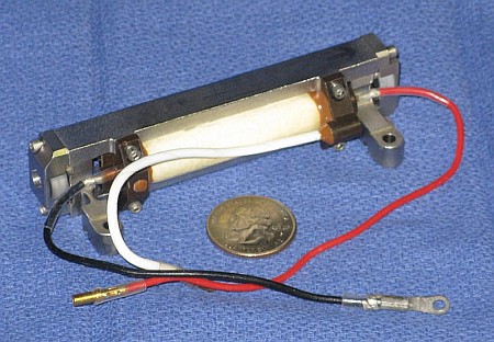
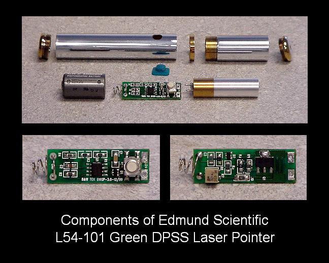
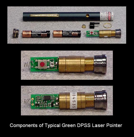
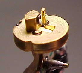
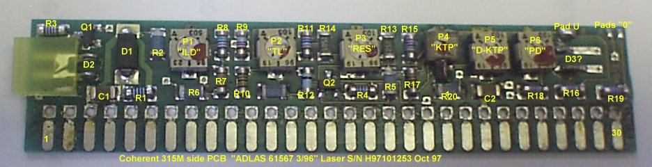
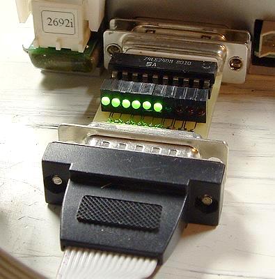
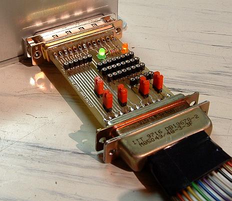
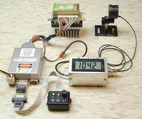
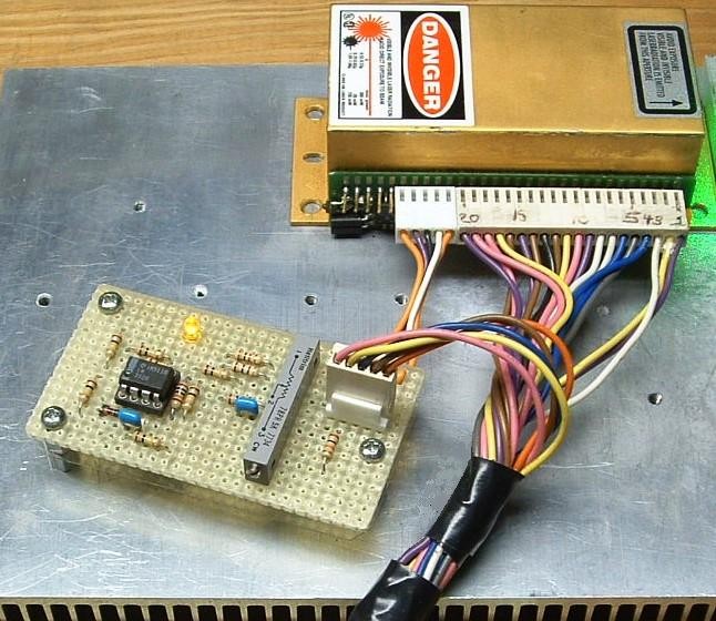
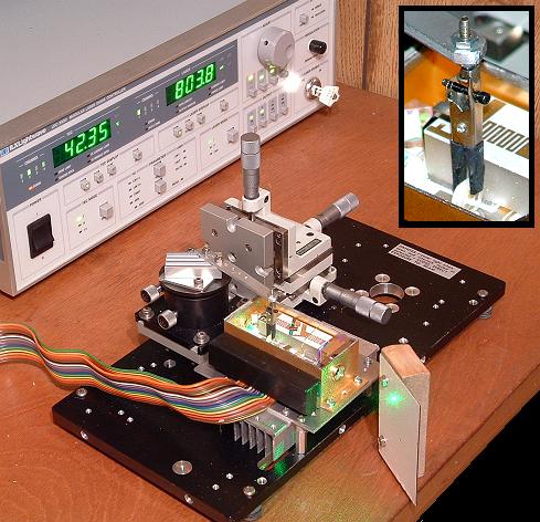
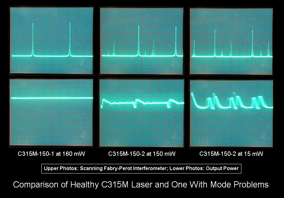
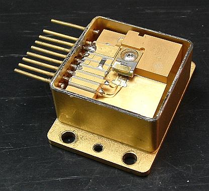
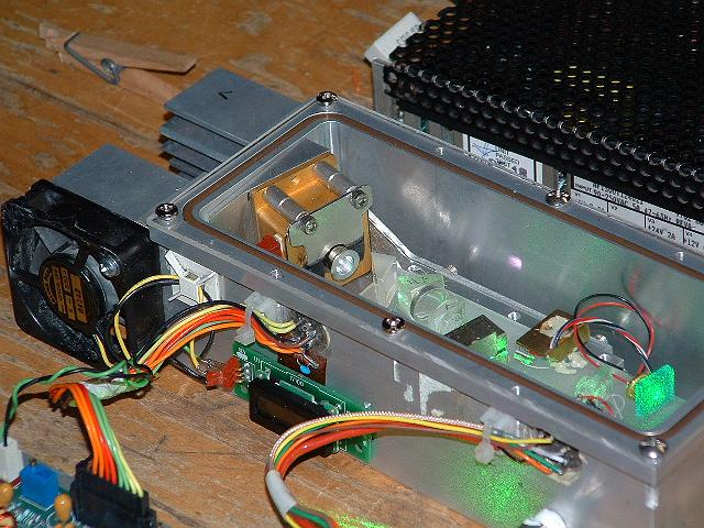
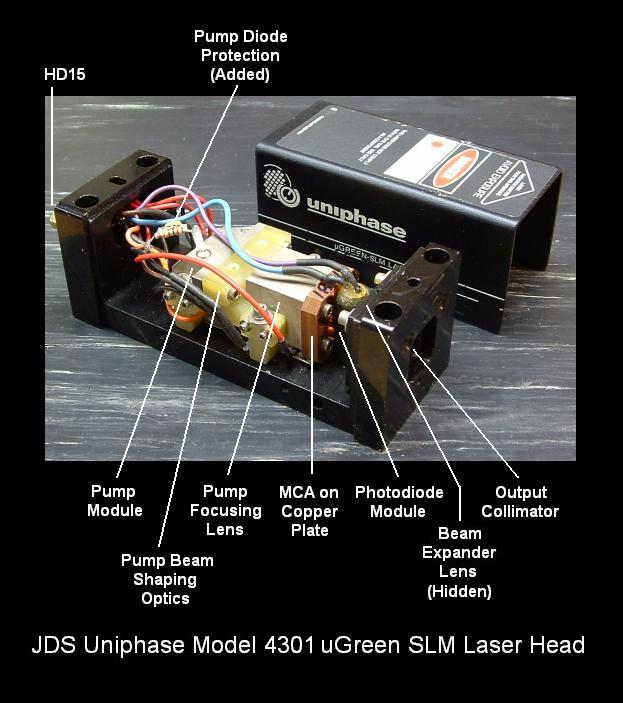
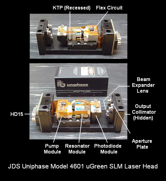
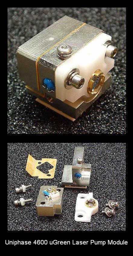
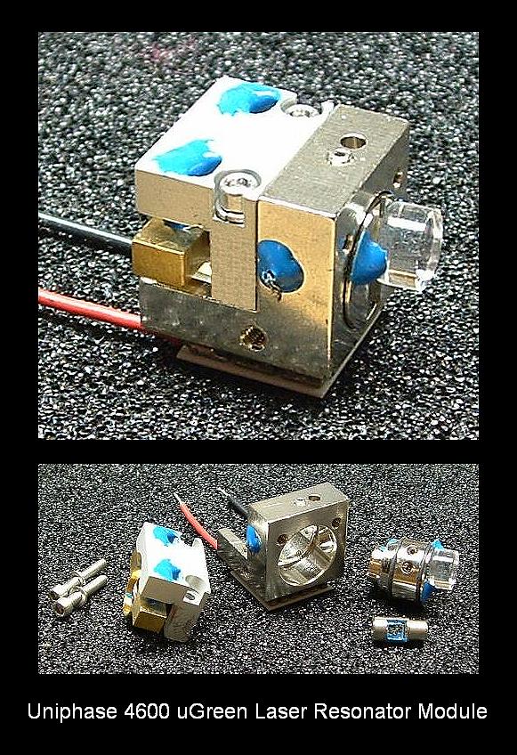
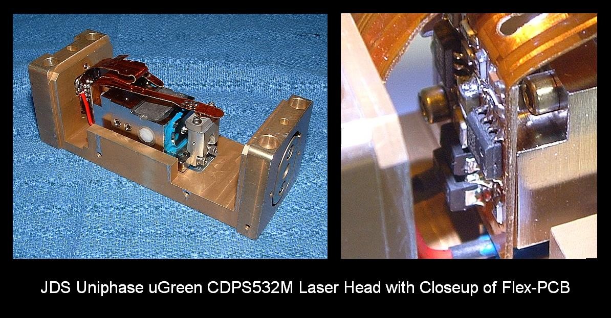
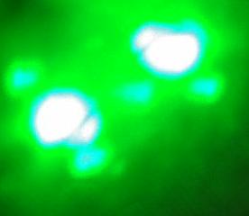
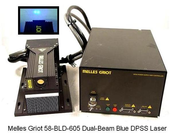
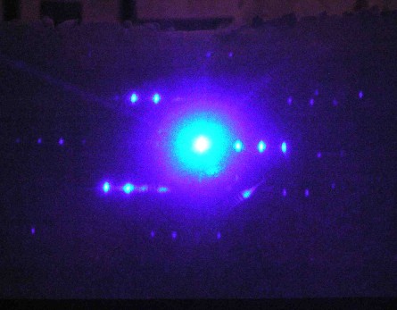
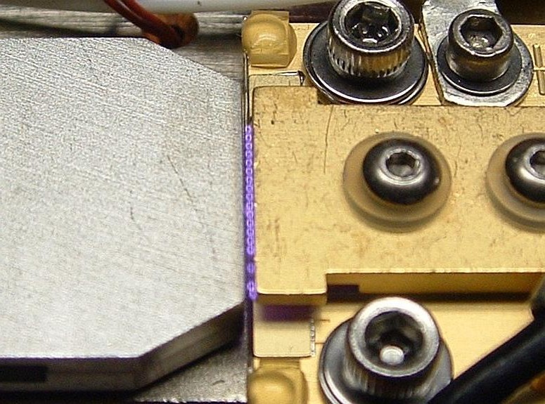
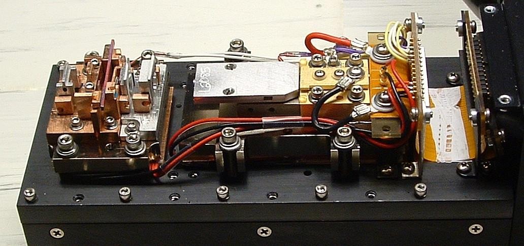