Currently, they are just suggestions. (If you can't wait, there are also some links to Web sites with educational laser projects below.) Eventually, additional details of the setup and required supplies will be added. Where the particular topic is already discussed elsewhere in Sam's Laser FAQ, a link to that section will be provided. However, in most cases, at least some of the details will be left as an exercise for the student. What fun or challenge would it be if we told you everything? After all, besides its educational value, hands-on experience should indeed be both fun and challenging! However, where more information is available in this document, links are provided.
A 1 to 5 mW internal mirror helium-neon laser will be suitable for most of the basic experiments (though a somewhat higher power one would be better for those like holography). It should be possible to procure such a laser for under $50, possibly under $25 depending on your resourcefulness and scrounging abilities.
Some experiments may require a polarized laser but for most, any type will do, even a better quality (one with an adjustable focusing lens) laser pointer - and those are practically given away in cereal boxes these days. :) Where access to the laser cavity is required, an external mirror HeNe or Ar/Kr ion laser will be needed. A one-Brewster HeNe laser setup can be put together quite inexpensively (probably under $100) using a surplus one-Brewster HeNe tube and power supply, the OC mirror from a deceased HeNe laser, and some scrap materials available in any well equipped junk box. Of course, if you have access to a nice lab laser, that would be fine as well but probably not nearly as much fun or as rewarding compared building one (at least partially) yourself. :)
Alternatives like bare laser diodes and appropriate drive circuitry may be more desirable for projects like laser communications where modulation is required. And, other color lasers (than the boring red HeNe or laser pointer) will be desirable for laser display.
See the chapter: Laser and Parts Sources. I also have a variety of suitable lasers and components available on Sam's Classified Page.
In addition, those experiments requiring access to the interior of the resonator of an external mirror laser may expose the user to potentially lethal voltages in the vicinity. If possible, any exposed high voltage terminals should be well insulated or blocked from accidental access. And, where all you have is an exposed HeNe laser tube and separate power supply, building all this into a safe enclosure is highly recommended.
Read the chapter: Laser Safety in its entirety and follow its guidelines - particularly in regards to the safety of others who may not be as aware as you in dealing with your equipment.
Basic principles:
Here is an optics site (not laser specific) oriented towards kids:
Also see the chapter: Laser Information Resources.
Now, what happens if multiple dielectric mirrors are placed in series? Under certain condition, more light will get through than might be expected. For example, using the same example as above, if T = .1 for both mirrors, the resulting output may actually be as high as for an equivalent mirror with T = .05 (rather than T = .01). Why? Under what conditions will this happen? How does the T factor of each mirror affect this behavior? What other factors are important?
(From: Skywise.)
I once made a two slit experiment using a piece of glass, two razor blades, some tape, and some water based acrylic paint.
First I painted the glass with the paint. I chose a dark green color which absorbed my HeNe light pretty well. To make a smooth single layer of paint I put two parallel strips of Scotch tape on the glass about 1/2 inch apart. Then I placed a drop of paint towards one end of the channel formed by the two pieces of tape. With a razor blade resting on the tape, I dragged the blade along the channel thus spreading a nice thin even coating of paint along the glass. With practice on how much pressure to apply I was able to get a very good strip of paint that wasn't too thick or thin.
While the paint dried I taped two razor blades stacked together. To get the razor edges closer together than the thickness of the blades I used a small piece of folded paper at the back edge of the blades so as to fulcrum the sharp edges of the blades closer together.
Once the paint was dried I quickly dragged the two points on the corner of the joined blades across the paint strip thus creating two parallel slits.
With practice on applying the paint, adjusting the gap of the blades, amount of pressure when scoring the paint, etc... I was able to successfully make two slits close enough that a raw beam from my 5 mW HeNe pointed at the two closely spaced slits caused diffraction in the far field.
It was quite fun and was very useful for demonstrating the wave nature of light.
More information with photos can be found in a link from: Skywise's Laser Picture Gallery.
See the sections starting with: Viewing Spectral Lines in Discharge, Other Colors in Output.
Locate a HeNe laser tube with an HR mirror that doesn't have any wedge and characterize its behavior. See the analysis in the section: Melles Griot Yellow Laser Head With Variable Output.
Here are some suggested experiments and questions to ponder using this rig:
More information can be found at the International School of Photonics Optogalvanic Page.
The optogalvanic effect can be observed even with a normal HeNe laser without external illumination. As the tube warms up, the longitudinal modes shift through the gain curve and and the output power - and thus the intracavity power - changes depending on where the modes are. For long healthy tubes, the change is small. But for short tubes especially where the output power typically varies by 20 percent or more, it is easy to see as the sustaining voltage changing in synchrony with the power fluctuations.
If the HeNe laser tube is accessible, mirror alignment can be altered temporarily thus changing output power which will have a similar effect. For a high power (e.g., long) tube, it can be quite dramatic. Just take care with respect to the high voltage, particularly at the anode-end of the tube. So do this at the cathode-end if accessible. Even so, use an insulated stick to *gently* press sideways on the metal mirror mount stem, which should change the output power, and as a result, the tube voltage and/or current. Don't press too hard though.
A Web search will find many more with greater or lesser amounts of hairy math. :) But the hairy math isn't really required to perform basic experiments. I constructed a Fourier Optics spatial filtering setup for fun (or out of boredom) as a grad student many years ago using a vintage Metrologic HeNe laser and assorted lenses and slides found around the lab.
It appears to be possible to modify a common (under $10 on eBay) 1.3 inch 240x240 pixel LCD to act as a full color Spatial Light Modulator (SLM). These LCDs are easily driven from an Arduino-compatible microprocessor board like the Atmega 328 Nano 3.0. There are Arduino libraries to drive them as well as demo programs to get you started. The LCDs are listed as something along the lines of: "1.3 Inch Color IPS TFT LCD Display SPI ST7789". Try a few variations and sort by cost to locate the least expensive. All the parts with the 7 pin connector for the interface should be equivalent. (But not those with only a ribbon cable unless you like to deal with micro-fine connector soldering.) There are also 320x240 pixel versions that should be similar but this has not been confirmed.
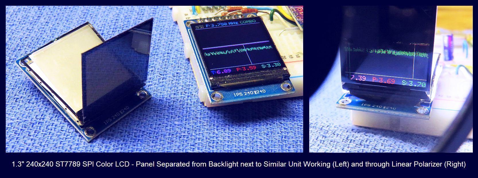
The ST7789 LCD assembly consist of an LCD panel with crossed polarizers glued to its front and rear surfaces along with an LED backlight and diffusers, and a PCB with the interface to the SPI bus.
Two modifications are required:
The modifications are straightforward but extreme care must be taken not to stress the LCD panel, which is similar in thickness to a microscope cover slip and easily cracked. The actual LCD module sits on top of the PCB with the interface connected, secured with RTV silicon or other adhesive. There is no need to remove it. See Color LCD Display Disassembled for use as Spatial Light Modulator.
CAUTION: Be extra careful not to stress the ribbon cable attached to the LCD panel. There is no practical way to reattach it if it comes off.
That's it! I've confirmed that this procedure works such that the LCD can be stood up with a separate linear polarizer and still displays correctly (as shown in the photo above) and that it works as the input SLM in a Fourier Optics setup. However, my success rate (after the first one which much have been beginners' luck) far from 100 percent due to the LCD panel cracking. So purchase some extra LCDs just in case. :( :)
These should be usable at both the input and filter planes, with a screen for the output plane and digital camera. However, the resolution is such that there may be serious limitations as to the effectiveness of the spatial filter depending on the focal lengths of the lenses used in the setup. The polarization of the input beam will need to be oriented horizontally or vertically and which way will determine whether 0s loaded to the pixels are dark or light as noted above. The default state for both SLMs should probably be to block light.
The LCD should be capable of displaying 65K colors, so it may be possible to use an RGB laser (3 beams combined) to do some type of multi-spectral image processing. However, the wavelength transmission functions of the RGB filters on the LCD will probably not be compatible with full color processing. As far as issues, I do not know how the structure of the pixels and filters on the LCD will affect the behavior but these (and others) would make excellent topics for experiments.
From experience in buying several dozen of these LCDs from various suppliers, a small percentage come up in what I've dubbed "8 Color Mode" whereby pixels can only be black or their respective color at full intensity regardless of what's loaded into memory. The cause is not known but is believed to be a bug in the ST7789 library which fails to properly initialize an internal register. Test for this before discombobulating them and/or reserve 8 Color LCDs for the Spatial Filter SLM, which is less likely to need gray-scale capability.
It may also be possible to use a re-purposed LCD like this for a low resolution digital projector, adequate for a heads-up status display or the like. That doesn't require a laser but would probably need some very excellent cooling to project an image of any size with adequate brightness to allow the LCD to survive for long. :)
Higher resolution alternatives to the 240x240 pixel LCD may include:
Note: Calculations indicate that the diffraction using the suggested lens focal lengths will be quite small and the resolution of the spatial filter SLM using these LCDs will be too low to provide much in the way of spatial filtering. Specifically, the first order diffraction at the maximum of 10 lines/mm or a period of 5 cycles / mm with alternating dark and light lines will result in an angle of ~0.2 degrees for an offset of around 1 mm at the spatial filter SLM. So there aren't a lot pixels to work with. AND due to abberations in the lenses, the ideal zero order spot size will not be as small as theoretically possible.
However, a test of an LCD as an SLM for the Object Plane has been performed successfully using the slightly modified setup shown in Implementation of Fourier Optical Image Processor using ST7789 LCD Spatial Light Modulators with Video Capture. The (not so exciting) video is shown in: ST7789 LCD SLM Test 1. This used a modified version of the ST7789 Arduino test Sketch loaded onto the Atmega 328 Nano 3.0 on an mLMA1 PCB with the modified LCD panel placed at the Object SLM position. Rather than using a screen and separate camera, the sensor was a Nikon D5100 DSLR (with no lens) set to Manual mode with its mirror locked in the up position. Since it has no lens with and thus no adjustable aperture, the only real control of exposure is by selecting the ISO film speed, but that was adequate to provide good results. Readily available free Windows video capture software provides real-time streaming from the camera via USB. The resolution is quite good and with optimal adjustment lens and camera position would be very sub-pixel. ;-) The D5100 is a DX format DSLR with a sensor approximately 0.6 x 1.0 inches and the 240 pixels of the SLM just cover the width of the sensor with 96 rows above and below being wasted. Using a full frame FX format would permit the entire 240x240 pixels to fit its 1.5x1.0 inch sensor vertically but those camera bodies are usually much more expensive. And alternative since there is plenty of sensor resolution - way more than needed - is to use optics to reduce its size. The could be as simple as a screen at the Image Plane with a normal camera with lens as in the generic diagram above.
Here are parts similar to what were used. The "Test" lines describe what were used for the video, above.
The beam from the laser must be linearly polarized to be usable with the SLM. (This is not a requirement for basic Fourier Optics experiments using only lenses and film slides or other patterns.) A polarized beam is most easily provided by a linearly polarized HeNe laser. But a similar result can be achieved by adding a linear polarizer in the beam path of a random polarized laser oriented at 45 degrees to the principle polarization axes of the laser. But this would cut the usable power from the laser by at least 50 percent.
The orientation of the laser's polarization to the beam expander and subsequent optics must be aligned with the X or Y axes of the LCDs and will depend on whether you want the pixels to be bright or dark (pass or block) with stored values of 0. The unpowered state is also off so simply orient the laser so no light gets through. The polarizer attached to the LCD panel must face away from the laser for both SLMs.
Tests: The laser was a JDSU 1137P (rated 5 mW).
The expanding lens was the objective lens from a Sony KES400 Blu-ray pickup mounted in a plastic adapter plate screwed to the front of the laser.
A spatial filter consisting of a positive expanding lens and precision pinhole aperture located at its focus may be required to clean up the beam (not shown). Commercial spatial filters are very expensive, but one can be constructed relatively easily.
Tests: No spatial filter.
Tests: 37.5 mm diameter miniscus achromat with focal length of 113 mm.
O-SLM is placed in the collimated beam but the exact location is not critical.
The OL is placed exactly 1 OL-FL from the O-SLM.
Tests: 37.5 mm diameter achromat with focal length of 154 mm.
Test 1: Not present.
The F-SLM is placed exactly 1 OL-FL from the OL.
The IL is placed exactly 1 IL-FL from the F-SLM.
Tests: 37.5 mm diameter achromat with focal length of 154 mm.
The S is placed exactly 1 IL-FL from the IL.
Tests: The 23.5 × 15.6 mm (nearly 1.0" x 0.6") CMOS sensor in a Nikon D5100 DSLR (lens removed with mirror locked in the up position) set for M (Manual mode) in place of screen and separate camera. Both videos and still photos can be taken in this way and live-streamed directly to a PC.
The ray traces between the Object SLM and Image Plane are just arbitrary to show that the light gets redistributed. Do not read any more into it than that. :)
HeNe lasers are readily available on eBay (or from me direct). Inexpensive lenses can be purchased from Surplusshed for about $4.50 each. The LCDs are available on eBay for under $5 each.
The ST7789 LCD provides a full color display when used normally with its white backlight, but with a red laser, all colors will be shades for red. ;-) It is not known how the RGB pixel filter array on the LCD will interact with the red light. It also has a ~0.1 mm grid pattern as a result of the 240x240 pixel array. One of the first things to do may be to see whether there is a way to make that less visible via spatial filtering. The LCD material is sandwiched between crossed polarizers. The one on the front is oriented vertically and gets removed in the modification of the ST7789 to convert it to an SLM. The rear polarizer is oriented horizontally. To avoid issues with inter-pixel bleed-through, the laser and the two SLMs should have their polarization axes at 90 degrees to each-other. So, the polarization of the laser should be horizontal, the Object SLM should be vertical, and the Spatial Filter SLM should be horizontal. (Or all should be rotated by ±90 degrees.)
Mounting of these components is left to your ingenuity but the diagram offers a serving suggestion. ;-) More below. High priced parts from Thorlabs or Newport can certainly be used if cost is no object, but precision is really only required for the location of the expanding lens relative to the input beam, and the axial positions of the lenses and SLMs. An optical rail with appropriate opto-mechanical parts is ideal but since the there should be no need to change the position of anything once set up, is not necessary. The use of wood blocks and 5 minute Epoxy would certainly be acceptable. ;-) Just DO NOT use Superglue™ or other cyanoacrylate-based adhesive, which tend to stick body parts together but more importantly, eat optics.
The Expanding Lens can be attached directly to the output bezel of the laser, either directly with 5 minute Epoxy, or on a plate with oversize holes (to provide some range of adjustment) matching its hole pattern. The distance between the Collimating Lens and Object SLM is not critical - they can be adjacent on the same mount. The distance to the CCD Camera or other readout device is also not critical. However the spacing of the Beam Expander and the SLMs to lenses (F) must be accurate and since the exact focal lengths of stock lenses can vary by 10 percent or more, must be set using the laser and patterns programmed into the SLMs (or suitable substitute slides).
As noted, I have partially constructed a version of the FOIP using a combination of commercial and home-built parts. This was supposed to be a student summer project but that apparently has not progressed as well as expected. A more detailed diagram is shown in Implementation of Fourier Optical Image Processor using ST7789 LCD Spatial Light Modulators with Video Capture.
It is on a 36 inch Newport URL-36 optical rail. This is more like a one dimensional linear optical breadboard than a classic rail since there are no movable carriers, just holes and slots. But since everything will be locked down once positioned accurately, real-time changes in location aren't needed. And the price on eBay was right. ;-) All the lenses are from Surplus Shed. The major lenses (all but the beam expander) are achromats (as shown) to enable multi-spectral processing as a future possibility. Using simple lenses would work for a single wavelength like 633 nm, but if a combined input beam with several wavelengths were used, the lenses would focus at different distances for them. The pinhole aperture/spatial filter won't be installed unless needed. Thorlabs lens mounts are used attached to standard 2 or 3 inch posts on the URL-36. The laser is in a set of 4-screw ring mounts providing centering adjustment so post holders are really not needed as long as all the posts are the same length. So far only the object SLM has been tested, jerry-rigged in position.
The laser is a Melles Griot 05-LHP-171 with an actual output of around 10 mW. The Expanding Lens is the objective lens from a Sony CD player optical pickup with a focal length of 4 mm. To conserve space, it is mounted directly to the end-cap of the laser on a plate to provide for centering adjustment. The Collimating Lens has a focal length of ~150 mm resulting in an expansion factor of around 38 so the 1 mm beam from the laser becomes 38 mm in diameter (1/e point) and covers the ~25x25 mm area of the SLMs. Also to save space, the Collimating Lens and Object SLM are attached to the same mount so they are close together, which saves space and the need for a separate post. The Fourier Lenses have a focal length of around 100 mm. All the large lenses have a diameter of around 42 mm. The mounts for the SLMs and Image Plane screen are plastic 35 mm slide holders attached to metal brackets screwed to standard 1/2 inch posts. Everything fits on the 36 inch rail, though part of the laser extends off the back end.
As noted, the polarization orientation of the laser and SLMs must be selected such that both SLMs block light in their off state. The reason for that is to assure that there is minimal light passed via the inter-pixel areas on the LCD. It is not known if this will be an issue, but default of block is safer. As drawn, the polarization of the laser is horizontal, the Object SLM is oriented with its pins at the top or bottom, and the Spatial Filter SLM is oriented with its pins to one side. For both SLMs, the side that would normally be buried inside facing away from the viewer is at the output - to the right.
A pair of Atmega 328P Nano 3.0 microcomputer boards (or the Arduinos of your choice) can be used to drive the LCDs with short extension cables. Demonstration sketches are available from several Web sites which can easily be modified to do whatever you want. See, for example, Interfacing Arduino with ST7789 TFT Display – Graphics Test Example. This uses an Uno but the Nano is virtually identical. See the info in Mini Laser Mode Analyzer 1 (mLMA1) Version 2 for the specific wiring.
Stay tuned.
Assuming a function generator and oscilloscope are available, it is possible to build an SFPI that demonstrates basic principles for next to nothing, or one that rivals the performance of commercial instruments costing many thousands of dollars for less than $100. Or even an SFPI that has 2 orders of magnitude higher resolution. See the sections starting with Sam's $1.00 Scanning Fabry-Perot Interferometer. Even this very simple SFPI using salvaged mirrors will easily resolve the longitudinal modes of a HeNe laser.
I offer sets of mirrors and other parts for a variety of SFPI from one about 1 inch in length suitable for a basic mode display to high high resolution SFPIs up to 22 inches in length that can resolve the two modes of most axial Zeeman-split HeNe lasers - a resolvance of better than 500 kHz. And even an ultra-high resolution SFPI that is 10 times better than that. Most are now on eBay under my ID: siliconsam. Search for "Scanning Fabry-Perot Interferometer Kits".
Also see the section: One and Two Mode Stabilized HeNe Lasers.
All that is needed is a short HeNe laser tube to which a heater has been added, some optics and photodiodes to sample the amplitude of either one mode polarization or two mode (orthogonal) polarizations, and some basic electronic components to implement the control loop.
See the section Inexpensive Home-Built Frequency or Intensity Stabilized HeNe Laser for more information on what's involved.
I may be able to provide a set of parts including a well behaved HeNe laser tube, HeNe laser power supply, beamsplitter(s), photodiodes. Some mechanical skills will be required to mount everything. The electronic components can be obtained from places like Digikey or Jameco.
For looking at the longitudinal mode beating, a photodetector and oscilloscope with a response beyond c/2L for the HeNe laser will be required. This would be 500 MHz for a 12 inch long tube (mirror to mirror). So a longer tube would be desirable both due to its lower beat frequencies and more modes. For the second order difference frequencies, the photodetector still has to be fast but the scope only needs to respond to 100 kHz or so.
There are at least two arrangements primarily differing whether the magnetic field is oriented along the optical axis of the tube (axial) or perpendicular to it (transverse). Of course, no law prevents experimenting with the field at other orientations!
Here is a summary of the basic procedure for Zeeman splitting using an axial magnetic field. The following components are required:
Set up the components in a reasonably stable manner. The polarizer just needs to be in the beam - its orientation doesn't matter since it's simply converting circular to linear polarization.
Using a scope (preferably) or frequency counter, look for a beat frequency from the detector. The HP 5501 tube is very stable - its frequency will only vary by a few percent over several minutes. The frequency of the HP 5517 tube varies quite widely in a periodic manner as mode cycling takes place due to heating. The beat may disappear totally during part of the cycle. This behavior is very similar to that of the home-built version.
Adding some means of cavity length stabilization would be the next step.
Experiments can also be performed without the tube inside the ring magnets by trying various positions and orientations of external magnets. It may even be interesting to put the output through an audio amp and speaker as the beat frequency with a smaller magnetic field will cover the audio range.
Here is a summary of the basic procedure for Zeeman splitting using an transverse magnetic field. The following components are required:
Set up the components in a reasonably stable manner. It will be necessary to determine the natural polarization axes of the tube. Orient the magnets their field parallel to one of the axes and the polarizer at 45 degrees to one of the axis. Using a scope (preferably) or frequency counter, look for a beat frequency from the detector. Depending on magnetic field strength (i.e., how many magnets are used and how close they are to the tube), there will be a beat signal over part or all of the mode sweep cycle. Experiment with various configuration of the magnets.
To observe the polarized mode amplitudes, some additional optics for beam sampling will be required, along with photodiodes and possibly some simple electronics and a low speed data acquisition system to record the data.
This type of laser can also be frequency stabilized since the beat frequency varies with mode position. A Phase Locked Loop (PLL) is generally used but a simple Frequency-to-Voltage (F-V) converter and op-amp will work in a manner similar to that of the polarized mode stabilized lasers.
Many common materials like Nd:YAG have a small Verdet constant, though it is still sufficient to enable a strong magnet to produce enough of an FR effect to be used in forcing unidirectional operation of a ring laser. However, there are some special materials with very large Verdet constants. Terbium-doped glass has V = 65 deg/(T*cm) (T = Tesla = 10,000 gauss). And Terbium Gallium Garnet (Tb3Ga5O12 or TGG) has a Verdet constant about twice as large.
To put this in perspective, a 2 cm long rod of terbium-doped glass will rotate the polarization by 10 to 20 degrees if inserted inside a stack of two ferrite magnetron magnets. Even a "refrigerator" magnet of around 100 gauss will result in a detectable effect if the rod is between crossed polarizers or a polarizer is used with a linearly polarized laser. And 100 degrees or more is possible using a tabletop magnetic pulser. See the next section.
Pulser electronics:
The pulser dumps the energy in a charged capacitor bank using the flashlamp from a disposable camera as the switch. I'm using an unregulated linear HeNe laser power supply on a Variac as the capacitor charger for 5 uF at 2,000 to 2,500 V using a pair of 10 uF, 1,500 V capacitors in series with equalizing/bleeder resistors of 1.6M ohms on each. (Actually 4, 400K ohm, 2 W resistors in series.)
WARNING: The energy stored in this capacitor bank can be quite lethal. It's greater than that for a microwave oven capacitor.
The flashlamp has a self breakdown voltage of about 2,500 V so it alone can make a really big relaxation oscillator. But, the breakdown voltage is not nearly as consistent as with an NE2 neon lamp, so the rate of flashing using self-breakdown was highly erratic. So I used some of the remaining components from the flash unit to provide a manual trigger. The voltage for the trigger capacitor is taken across the bottom bleeder resistor. The single flashlamp is marginal at 2,500 V since it likes to fire on its own - two in series would probably be better. But this way, it lets me know not to try to push my luck at higher voltage. Most of my subsequent tests were done at just under 2,500 V so that it would not flash on its own. Charging requires about 15 seconds which results in a conservative average power for the solenoid, which would be the limiting component.
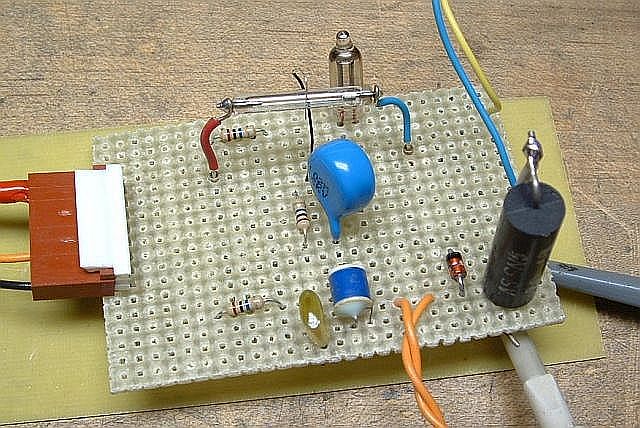
See Photo of Magnetic Pulser Flashlamp Switch and Trigger Circuit. The neon bulb will be lit when there is more than 60 V across the flashlamp so it serves as a danger indicator. The large blue capacitor isolates the trigger wire from the trigger transformer so that even if the flashlamp arced to the trigger wire, it wouldn't go any further. And note that the trigger wire isn't even near the flashlamp. When any closer, the flashlamp would self-fire at less than 2,000 V. The large black cylindrical object is the 0.2 ohm current sense resistor, with a scope probe and ground clip visible attached to it. The yellow and blue wires go to the pulser coil and the orange wires go to the remote trigger pushbutton.
The pulser coil is from an actual magnetic solenoid used to actuate some sort of something or other. ;-) It was carefully selected because the bore size was correct for what had to go into it. :) With the rear pole piece drilled out and removed, it has a nice magnetic yoke to complete the magnetic circuit outside the bore of the solenoid. It's pure luck that this sort of thing survives being pummeled with pulses of nearly 2,500 V, as its normal operating voltage is 24 VDC. But so far so good.
Laser and optics:
I'm determining the magnetic field using a special type of magneto-optically active glass (M18, available at exorbitant cost from Kigre, though I'm sure if it's a listed product, mine is a sample on loan). This material exhibits a strong Faraday effect, rotating the polarization of a beam of light in proportion to the axial component of the magnetic field. The sensitivity of the Faraday Rotation (FR) in M18 is about 123.5 degrees per Tesla (10,000 gauss) for the 1.9 cm long rod. And, at nearly 2,500 V, I'm exceeding 1 T.
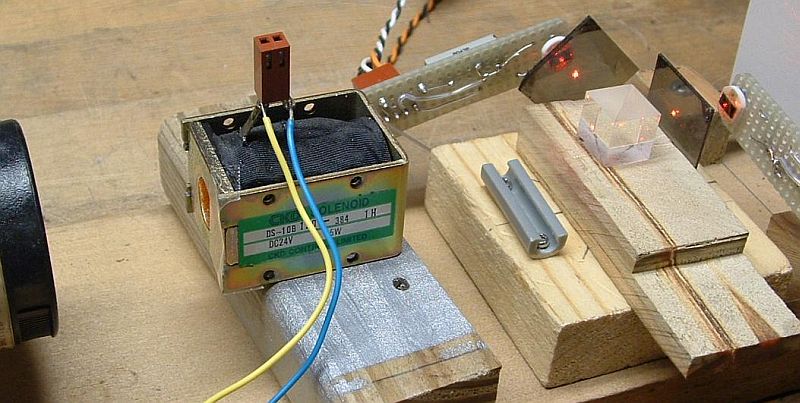
The very high class optical setup is shown in Optical Setup for M18 Faraday Rotation Experiments. Now these are true optical breadboards! :) It consists of a polarized 5 mW HeNe laser, the M18 rod (hidden inside the hole in the solenoid - note the piece of clear tape to prevent it from falling out accidentally if the solenoid is tipped!), a Melles Griot non-polarizing beamsplitter cube followed by a piece of Polaroid-type linear polarizer for each exit, and a reverse biased $2 photodiode with a 3.3K ohm load resistor.
While using a polarizing beamsplitter to obtain orthogonal vertically and horizontally polarized outputs might be expected and is often used in similar experiments, this is not optimal. Why? Because they don't provide much additional information compared to a single signal, being essentially complements of each-other. Having multiple signals may help reduce noise and eliminate offsets due to non-polarized light. However, they don't permit the determation of the direction of rotation if the input polarization is initially aligned with one of the polarizers (e.g., 0, 90, 180, or 270 degrees), or make it possible to disambiguate a change in rotation direction that may occur near one of these angles.
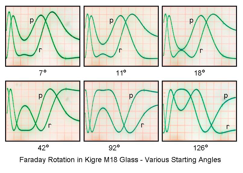
Therefore, in this setup, the polarizer for one of the photodiodes is oriented at 90 degrees but the other one is oriented at 45 degrees. Their outputs are called p and r, respectively. (The designations p and s are for polarizations at 90 degrees to each-other, thus the r instead of s. And, what I've called p may not be in universal agreement with everyone's definition. So, just think of them as two variables!) They provide quadrature signals in the same way as in a rotary encoder, so the output rotation will always be unambiguous. Since a full cycle of the polarization is 180 degrees rather than 360 degrees, the quadrature angle needs to be 45 degrees instead of 90 degrees but it's the same principle. (More on the angle doubling due to Malus' law below.)
The outputs of the photodiodes (PDs) go to the two channels of an analog scope, which unfortunately has no storage capability. This is one time I'd prefer a digital scope or data acquisition system! The trigger comes from a current sense resistor of 0.2 ohms, which was also used initially to determine the actual current in the coil. Since the scope has a "trigger view" function, the current (I) can be displayed as a third trace, since it is already used for triggering.
With the 5 uF energy storage capacitor bank, the pulse duration is about 2.5 ms and the system is just slightly underdamped. The peak current is 12 to 13 A into a coil with a resistance of 120 ohms. Based on the dimensions and resistance of the coil, it has approximately 2,700 turns of #32 AWG wire, producing more than 32,000 peak A-T. (This was found using the equations in the section: "Estimating the Number of Turns of Wire in a Coil" in the document: "Notes on the Troubleshooting and Repair of Small Household Appliances and Power Tools" of the Sci.Electronics.Repair FAQ.) However, the large number of turns results in a high inductance which is far from ideal. A smaller number of turns of thicker wire would be much better but scroungers can't always be too selective. For example, if there were 1/4 the number of turns of wire with 4 times the cross-sectional area, the resistance would be 1/16 and the current could be 16 times larger with the ampere-turns being 4 times as large so the magnetic field would be larger (subject to saturation effects of the iron of the yoke). This might be a bit much for the flashlamp from a disposable camera, but not for a larger one. Rewinding the solenoid might be possible but the yoke is not designed to be easily disassembled.
While the energy of the capacitor at 2,500 V is about 15 Joules, most of this is dissipated in the coil so the flashlamp isn't being stressed. I'd guess the dissipation there is under 1 Joule.
Plots of actual data:
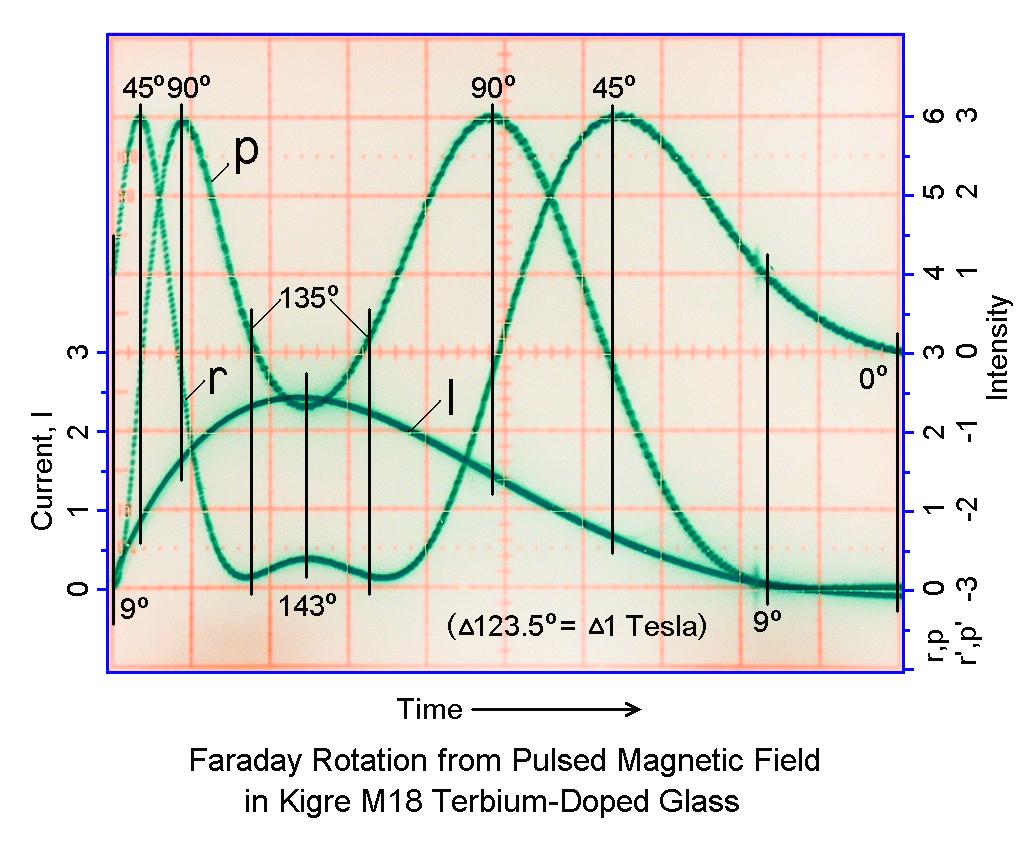
Faraday Rotation from Pulsed Magnetic Field in Kigre M18 Terbium-Doped Glass shows the results. Note that the initial angle is 9 degrees, not 0 degrees. The total change in rotation angle is about 134 degrees corresponding to a peak magnetic field of about 1.1 Tesla (11,000 gauss). This is a negative of a photo taken with a older cheap digital camera from an analog scope, thus the strange colors. :). (The camera has no sync input or output, and no manual focus. And, to get good contrast on the scope trace, the room had to be nearly dark - and autofocus wouldn't work. So, with the camera on a tripod, it came down to (1) turn the lights on to lock in focus and exposure by pressing shutter the button halfway, (2) turn the lights off while continuing to hold the shutter button halfway, (3) depress the shutter button fully to take the photo, (4) as soon as the fake click of the shutter opening is heard, press the trigger button on the pulser and hope this was done fast enough for the pulser to fire while the shutter is still open. It worked about 2/3rds of the time.)
Using the actual value of the current of 12 A measured with the 0.2 ohm sense resistor, the dimensions of the coil, and an estimate of the number of turns, the resulting magnetic field is 1.3 T, which is remarkably close to the measured value of 1.1 T considering all the assumptions and hand waving. :) There should be inaccuracies introduced because this coil has multiple layers and because there is an iron yoke completing part of the magnetic circuit.
The plot above shows the complete event except for the very tail of the current pulse. The three traces are the current, I (scale on the left) and r and p optical power (or intensity, scale on the right). A scale for signals r' and p' (to be described below) is also provided on the right. The units are arbitrary, based on the scope graticle. I believe the slight skew between r and p is a combination of the linear polarizers not being oriented at exactly 45 degrees and the beamsplitter cube transmission and reflection being slightly polarization-dependent even though it's supposed to be non-polarizing. The response of the M18 glass is very fast - probably in the 100s of GHz range if not higher - so that is not an issue here since these pulses are on the order of milliseconds.
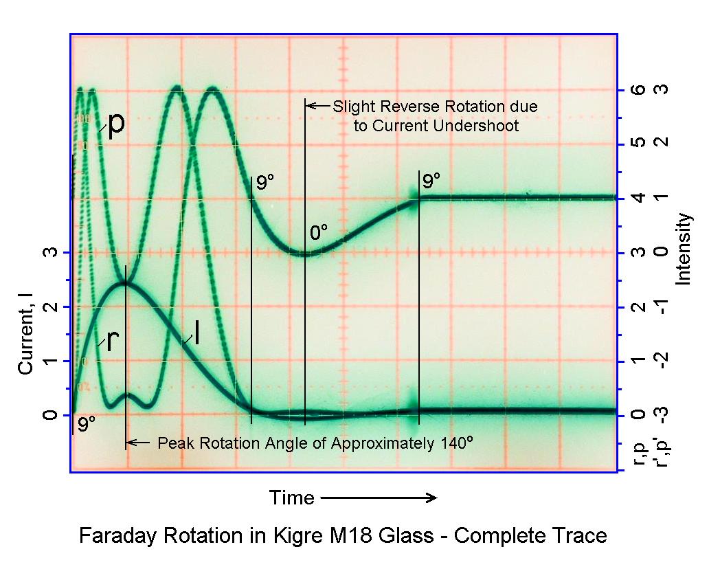
Note that the electrical system is slightly underdamped so the current, and rotation angle, go a bit negative near the end. Faraday Rotation in Kigre M18 Glass - Complete Trace shows all the gory details. (Note that this is a different shot so the values are not quite identical.) When the current is descreasing and crosses zero going negative, the flashlamp is still conducting. But when the current attempts to cross zero going positive, the flashlamp apparently cuts off and thus the glitch before it flat-lines. Note that the magnitude of the negative current is quite small - less than 5 percent of the peak - but since r is changing rapidly at around that point, it looks a lot worse than it really is. The two pin connector attached to the solenoid terminals (visible in the photo) was intended for a snubber circuit to eliminate the undershoot, but it never was installed.
And, see Faraday Rotation in Kigre M18 Glass - Various Starting Angles for the appearance with the a bunch of randomly selected input polarizations, obtained by rotating the HeNe laser. :) (No effort was made to assure that the gain and offset of the r and p signals were exactly the same in each case, so they aren't.) Using a Half Wave Plate (HWP) in front of the laser to set the initial polarization angle, and for adjustment of the polarizers and detector electronics so the signals are precisely orthogonal and have equal gain and offset, would be better than rotating the entire laser since it will have no effect on beam alignment. However, the HWP would have to be closely matched to the laser wavelength to maintain pure linear polarization.
Calculating the rotation angle:
The rotation angle can be easily obtained using Malus' law and a bit of trigonometry. Remember that? :)
Malus' law relates the intensity of light passed by a polarizer to the angle between a linearly polarized input beam and the polarizer, or equivalently, to the angle between polarizers if using non-polarized light.
I = Io*cos(theta)2where Io is the intensity at 0 degrees and I is the actual intensity.
With a photodiode monitoring a fixed beam profile, intensity will be proportional to power. For the Faraday Rotation (FR) setup, there are a pair of polarizers offset by 45 degrees producing two signals, r and p:
   r = Io*[cos(theta-45)]2 and
   p = Io*[cos(theta)]2
where r and p are the actual photodetector signals with a minimum value of 0 and a maximum value of Io.
Note that this assumes both signals have the same minimum value (0) and maximum value (Io) as in the plot, above. Otherwise, appropriate adjustments should be made to eliminate any offset(s) and to make their scaling factor the same. I in fact did this by adjusting the vertical channel position and gain controls on the scope before taking the shots. This was done by rotating the laser to set the minimum and maximum on the display to be the same for both signals. Where they have already been captured, "adjustments" will need to be done on the data. This is left as an exercise for the student!
Continuing on using a basic trig identity:
   r = 0.5*Io*[1 + cos(2*(theta-45))] and
   p = 0.5*Io*[1 + cos(2*theta)]
This angle doubling is what results in 45 degrees being the required quadrature angle between r and p.
Simplifying:
   r = 0.5*Io*[1 + sin(2*theta)] and
   p = 0.5*Io*[1 + cos(2*theta)]
Then:
    r - 0.5*Io     sin(2*theta)
   ------------ = -------------- = tan(2*theta)
    p - 0.5*Io     cos(2*theta)
Solving for theta:
                       r-0.5*Io
   theta = 0.5*arctan(----------)
                       p-0.5*Io
Or defining the halfway point for r and p and using values relative to it, calling them r' and p', which may be intuitively easier:
                       r'
   theta = 0.5*arctan(----)
                       p'
Both equations are subject to the condition that the rotation function must be continuous. A value of +/-(n*90) or +/-(n*180) degrees may need to be added to theta to achieve this since the arctan function can fall into the wrong quadrant.
I used MS Excel to confirm expected behavior for the data in the plots, above. In addition, the angles were estimated using the current trace relative to maximum current (based on values in the plot normalized to the peak magnetic field as determined from r' and p'). All the annotated angles are included along with a few intermediate easy to record ones:
   PD Signals             Angle   Angle from  Sensed   Angle from
    r'     p'   2*theta   Adjust   r' and p'  Current   Current
 ------------------------------------------------------------------
   1.00  -2.95  -18.7°      +0°       9.4°     0.15       11.6°
   2.00  -2.00  -45.0°      +0°      22.5°     0.45       29.1°
   3.00   0.00   90.0°     +90°      45.0°     0.80       49.4°
   2.00   2.00   45.0°     +90°      67.5°     1.25       75.6°
   0.00   3.00    0.0°     +90°      90.0°     1.65       98.9°
  -2.00   2.00  -45.0°     +90°     112.5°     2.00      119.3°
  -2.90   0.15  -88.0°     +90°     133.5°     2.30      136.7°
  -2.60  -0.70   74.9°    +180°     142.5°     2.40      142.5°
  -2.90   0.15  -88.0°     +90°     133.5°     2.20      130.9°
  -2.00   2.00  -45.0°     +90°     112.5°     1.85      110.5°
   0.00   3.00    0.0°     +90°      90.0°     1.40       84.4°
   2.00   2.00   45.0°     +90°      67.5°     1.05       64.0°
   3.00   0.00   90.0°     +90°      45.0°     0.65       40.7°
   2.00  -2.00  -45.0°      +0°      22.5°     0.30       20.4°
   1.00  -2.95  -18.7°      +0°       9.4°     0.05        5.8°
   0.00  -3.00    0.0°      +0°       0.0°    -0.05        0.0°
   1.00  -2.95  -18.7°      +0°       9.4°     0.10        8.7°
The values for r', p', and current (I) are from the plots and not volts or amps! And they were only slightly fudged. :) Due to the small skew in the r and p polarizers, I had to estimate some values where one of the signals was changing rapidly and didn't line up with the other as expected. In principle, I could go back and reshoot the data but that isn't going to happen! I was also trying to reconcile my inability to match up the magnetic field from the r and p signals compared to the magnetic field predicted by based on current. Then I realized that there is real hysteresis in the response of the solenoid's magnetic field with respect to the current. The magnetic field lags behind the current. So, the actual magnetic field (from r and p) is smaller than what would be predicted based on ampere-turns when the current is increasing and larger when the current is decreasing. Interesting. It's also possible that some or all of the hysteresis is in the response of the M18 glass to the magnetic field but based on what is found in the literature, this doesn't seem very likely.
Why the Faraday rotation experiments were done:
The reason I got involved is that a grad student at Cornell is using the stuff to measure high magnetic fields in plasma physics experiments and I decided I wanted to play as well. The peak magnetic fields involved in the research are only about 50 percent greater than what I have achieved, but the pulse duration is shorter by nearly 4 orders of magnitude. This requires more expensive detectors, high speed data acquisition, and super shielding in the vicinity of million amp current pulses, but is fundamentally the same problem. I will describe the actual details in the future. :-) But for now, see Magnetic Field Measurements in Wire Array Z-Pinches (Poster) and Magnetic Field Measurements in Wire Array Z-Pinches and X-Pinches (Paper) if you are curious. But more recent results are far more convincing.
                                                      o--- NC (Light)
                                            COM ---o/
                                                      o--- NO (No light)
       +6 V o-------+---------+---------------+----+
   (4 AA Cells)     |         |               |    |
                    |         \              _|_    )|| K1
                    /         / R3    1N4148 /_\    )|| 6V coil
                    \ R1      \ 1.5K          |     )|| 500 ohms
                    / 3.3K    /               |    |
                    \         |               +----+
                    |         |                    |
                  __|__       |      5.6K      B |/ C
     LIGHT ---->  _/_\_ PD1   +------/\/\--------|    Q2 2N3904
          Sensor    |         |                  |\ E
        Photodiode  |     B |/ C                   |
                    +-------|    Q1 2N3904         |
                    |       |\ E                   |
                    \         |                    |
                 +->/ R2      |                    |
                 |  \ 100K    |                    |
                 |  / Sens.   |                    |
                 |  |         |                    |
    Return o-----+--+---------+--------------------+
Basic experiements can be performed with just a laser pointer, solar cell, and audio amp. However, keep in mind that to really get any decent performance is not a trivial undertaking. Sound is likely to be distorted and noisy with contributions from both inside and outside. And just getting enough optical return off a window unless at precisely normal incidence will be a challenge in itself. Here is one link that appears to have rather detailed information: Laser Microphone.
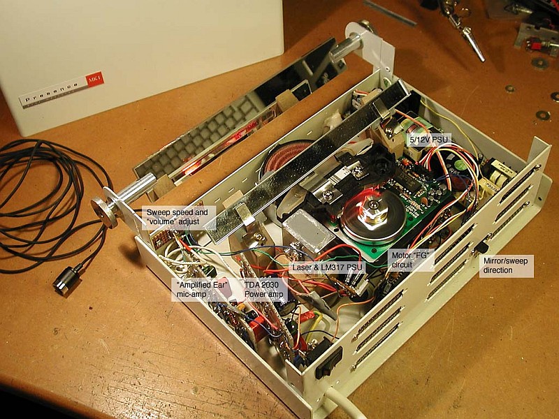
Ever since I first ripped apart a laser printer I've known that those spinning mirrors and weird optics would be perfect for a laser oscilloscope, but I didn't have any lasers powerful enough and didn't really know where to begin, so the idea just kept rattling around in my head. Until now. A while ago I came upon a cheapo video DVD-burner with a fried PSU. That was the laser I'd been waiting for. And largely thanks to this amazing site, I found out how to use it.
The thing is built around a square rotating mirror sweeping the laser beam, a few flat lenses pulling the sweep together to about 30 degrees, and a speaker voice-coil tilting a long narrow mirror around a hinge. Bror Westblad's Mark-I Laser Oscilloscope Optical Path. Through the "Amplified Ear" AGC amp from RED Free Circuit Designs, a microphone picks up any sound in the room and displays it on a nervous red line on the wall. The effect is quite eerie, but on a well lit gallery wall it doesn't have quite the visual punch I was hoping for. It appears that even a painfully bright laser spot becomes rather feeble when stretched out to a two meter long line.
Here's all I know about the laser: The DVD-burner was dead, so I just ripped out the optical module, and, as it seemed people do that sort of thing, I hooked up the laser straight to two not so peppy Duracell rabbits and, hey presto, light! Then I looked into power supplies, and ended up building SG-LD1. That worked perfectly when I tested it with dummy LEDs and a photodiode. But not with the laser! The LD is an "open can" thing, which let me inspect it properly with a 24x magnifier and, what do you know, there is nothing connected to the PD pin! (The pin was soldered to ground/case in the unit, but I wrongfully assumed that it just wasn't in use. Well, it wasn't even there!)
So, I ended up building that super simple LM317 PSU. And now it works. But, I've no idea how much current I can feed the laser. The thing is, when I turn the power up, the output increases smoothly and I don't really see any distinct threshold. At 60 mA the output is about as bright as from a regular 1mW laser pointer. When I initially tested the laser with the batteries it drew 84 mA, so I guessed that to be some sort of max limit. So, in the final assembly, I adjusted the current to 81 mA.
Bror Westblad's Mark-I Laser Oscilloscope with Cover Removed is an annotated photo of the completed unit.
(From: Sam.)
You were quite lucky (assuming that it wasn't damaged by the initial test with the two Alkaline cells! The 84 mA just happened to be all the pooped out battery could deliver.
There is no real way to know what the upper limit is without either knoing the LD part number, or destroying a few. But many DVD burner LDs go up to 100 mW or more.
One of my students built a real time (60 iterations per second on a 512 x 512 grid) implementation using conventional video technology about 20 years ago. When displayed in this manner, the appearance can be truly mesmerizing.
This would be a natural for a laser display. The dimensions would not be restricted to common video formats but could be anything reasonable. While custom digital hardware including a full frame store had to be built 20 years ago to produce a real-time update rate, nowadays, a modern PC may be fast enough to result in an acceptable presentation.
A typical front surface aluminized mirror reflects about 90 to 95 percent of the light so there can be quite a few bounces before the beam loses so much intensity as to be undetectable. However, the quality of the mirror is also important so as not to distort or scatter the beam. Sources for these mirrors include barcode scanners and laserprinters. Back surface mirrors are considerably worse than front surface mirrors. Dielectric mirrors coated for the specific laser wavelength are by far the best, some reflecting 99.999 percent of the light.