Although one of the simplest in basic structure, given these requirements, the HeNe laser may not be the best home-built laser for the novice. In fact, it is deceptively simple and yet one of the most difficult gas lasers to construct from scratch. However, later in this chapter, we present a number of alternatives to the HeNe laser fully built from the ground up using beach sand and copper ore. Therefore, it is still possible to experiment with partially home-built HeNe lasers (beyond just wiring together a HeNe tube and power supply) using various proportions of your own ingredients without doing everything from scratch. :)
Take precautions to avoid eye contact with the direct or reflected beam, whether or not it is visible. This includes the 4 pairs of beams reflecting off the Brewster windows which may be quite strong.
Provide proper warning signs for both the laser radiation and high voltage. Keep pets and small children out of the area and make sure everyone present is instructed as to the dangers. The use of proper laser safety goggles for the specific wavelength(s) of your laser are highly recommended.
See the section: HeNe Laser Safety for more info. However, the home-built HeNe laser uses a different sort of power supply than CW commercial types (unless you are attempting something similar to one of these) so some of the specific details may not apply,)
For more information, see the chapter: Laser Safety and the more specific information in the section: HeNe Laser Safety. Sample safety labels which can be edited for this laser can be found in the section: Laser Safety Labels and Signs.
If anyone reading this has built (or even attempted) a HeNe laser from scratch, please send me mail via the Sci.Electronics.Repair FAQ Email Links Page!
(From: Mark Wilson (wilson_mark@htc.honeywell.com).)
"When I saw the Scientific American article on building your own HeNe laser, I decided that I wanted to build it. The Scientific American HeNe laser was extremely difficult to build and I could not have done it without a lot of help. I got Spectra-Physics to donate a set of laser mirrors to me, a glass shop in my home town to help me cut and grind the Brewster window angles on the tube. The tube was made from lead glass from a sign company, and I also used neon sign electrodes. The optical rail was a 3 foot long piece of 2"x6" extruded aluminum that I got from a glass company which used this material to make doors for commercial buildings.I followed the directions in the Scientific American article to the letter. I sealed the microscope slides to the glass tube using flexible colodian that I got from a pharmacy. I filled the tube at a sign company which had He, Ne, Ar and other gases on a glass manifold. I assembled the laser and made the power supply using a mercury rectifier tube and a neon sign transformer. I got the tube to lase for a brief time, but since it was not a hard-sealed tube it quickly died probably due to helium diffusion. The tube would light up but not lase for a while then that too stopped."
Refer to Typical Home-Built Helium-Neon Laser Assembly for a simplified diagram of the overall glasswork and power supply electronics.
Operation at wavelengths more than a few nm away from 632.8 nm (except possibly for 640.1 nm) would likely require changing the mirrors to have their reflectivity peak at that wavelength (unless they are very high reflectivity broadband coated), and using the appropriate angle for the Brewster windows (or implementing an adjustable Brewster angle as described in conjunction with the Home-Built Pulsed Argon and/or Krypton (Ar/Kr) Ion Laser Laser).
       H o----------+ T1                T2   +---------o HV AC
                     )||               ||=||(
              Variac )<--------------+ || ||(
              0-115V )||              )|| ||(
                  5A )||    Neon Sign )|| ||(       Well insulated
                     )||  Transformer )|| || +---+  HV wires to HeNe
                 +--+        9kV,18mA )|| ||(    |  tube electrodes
                 |                    )|| ||(    |
       N o-------+-------------------+ || ||(    |
                                       ||=||(    |
                                       |   | +---|-----o HV AC
                                       |   |     |
       G o-----------------------------+---+-----+
                                                _|_
                                               ////
However, there are two disadvantages to using a narrow bore:
I would recommend a one piece approach instead, with a thick-walled capillary fused directly to glass extensions (as used in the Vander Sluis et. al. paper) if your glass working skills and/or budget are up to it (or glued to metal extensions if using the no glass working approach).
No other aspect of the laser tube assembly itself is as important as the quality of the Brewster windows to the ultimate outcome of this project! While, certain types of distortion won't prevent lasing (some may even make it more exciting with complex mode structures), this is a complicating factor your first laser can do without.
The author of the SciAm article suggests the use of quartz instead of glass to minimize heat losses but that material has a high transmittance at the 3.391 um IR wavelength which interferes with operation at 632.8 nm (and other visible wavelengths). If you insist on quartz (perhaps to have the option of 3.391 um operation in the future), also obtain a pair of glass flats to add outside the tube to kill that line. If you do try lasing at 3.391 um, aluminum mirrors should be fine. This line will even lase with no mirrors (superradiantly) in a long enough tube.
CAUTION: Apparently, it is possible for an electron beam to be produced from the positive electrode during the high current bake-out step which can quickly melt a hole through the tube wall opposite the side-arm if left running for more than a few seconds. The visual effect will first be a spot of bright yellow sodium light from the point of impact. Use lower current and/or make that area of the tube (the outside of the turn) much thicker.
(From: George Werner (glwerner@sprynet.com).)
"I have read with interest your wealth of information on home-built HeNe laser because every problem you dealt with was one that we grappled with about forty years ago. I was a member of a group here in Oak Ridge that built the first HeNe laser in Tennessee about six months after Bell Labs announced the construction of theirs.Back in the 1960's we had a laser development group that decided that before we came out with a new kind of laser we should get laser experience by building one (HeNe) like Bell Labs. Ken Van der Sluis was the principal investigator. His prior experience with resonators was with the Fabry-Perot (FP) interferometer, so much of our construction was adapted from FP construction. The reflectors were 5 cm diameter in mountings that used 1/4 - 80 threads on the adjusting screws and Invar rods to maintain spacing, a case of overkill on every turn.
The finest window material we had were quartz FP flats 5 cm diameter x 1 cm thick, and these were cemented onto the Brewster-cut tube ends. Ken was measuring gain with a spectrometer, adjusting mirror angles, gas mix, gas pressure, and discharge current, trying to find the magic combination but with no luck. Then Ken realized that it was possible that the infrared transition at 3.391 um was depopulating the upper level of the transition we wanted to use. After adding a borosilicate crown glass (BSC) flat (which blocks 3.391 um) to one of the windows with masking tape, and some realignment of the mirrors, it wasn't long before he got the first spark of red light - the first HeNe laser light in Tennessee! Soon word got around and for the next day or two we had dozens of visitors to see this fascinating red sparkling light. (It was our opinion that Bell Labs did not know about the 3.39 um trap and that they were lucky to have tried BSC first.)
The lasers we made were made to get that sparkly red light and we were not concerned about the mode structure (except for our theoretical physicist who was fascinated by all the different multi-mode patterns we could get with our wide bore tube and he had names for them all). In fact, we soon abandoned using thick Brewster windows with optically flat surfaces, and sometimes used ordinary microscope slides.
This work led to our development of a demonstration laser which we took to universities and a few high schools mostly over the eastern United States, and also to South America and Hungary.
Everything can be found in the paper: "A Simplified Construction of a Helium-Neon Visible Laser", by K. L. Vander Sluis, G. K. Werner, P. M. Griffin, H. W. Morgan, O. B. Rudolph, and P. A. Staats in the American Journal of Physics, vol. 33(3), pp. 225-240, March 1965.
(Here is another paper from the same group at Oak Ridge National Lab that should probably be in another chapter but I put it here: "Conversion of a Simplified HeNe Gas Laser to Pulsed Operation with Ar, Kr, and Xe", H. W. Morgan, P. A. Staats, P. M. Griffin, G. K. Werner, and K. L. Vander Sluis, American Journal of Physics, vol. 37(9), pp. 938-939, September 1969. --- Sam.)
My most important contribution to the effort was that I was the inventor of the Laser Alignment Card, which you allude to later in this chapter. I could go on for several pages talking about lasers. We old-timers love to talk and reminisce!"
(George has since gone on for several pages talking about lasers and has contributed several sections relating to the home-built HeNe laser, amateur laser construction in general, and other laser topics.)
The HeNe laser presented in the paper is very similar to the SciAm design which isn't terribly surprising given that it was published in the same time frame. A photo in the paper shows the minimalist approach to laser design - the laser tube as well as the resonator mirrors supported by chemist's burette clamps on wobbly ring-stands with a Tesla-type leak tester for excitation! Well, maybe. Some of may partially home-built laser test rigs were a lot less stable. :) OK, this isn't what they recommend building (or what is described more fully in the paper and below) but it was included to drive home the point that you don't need a lot of sophistication to construct a working laser.
I really liked the suggested supplier list (with 1965 prices!) which was thoughtfully included with my copy of the reprint of the paper. Optical windows for 25 cents; 1 liter flasks of He:Ne gas mixture for $6.50, and (small) neon sign transformers for $9.95. If only these companies were still n business today (using those same prices)! What I would give for a working time machine. :) One interesting thing is that while some items were quite inexpensive (if inflation wasn't taken into account), the dielectric mirrors were priced quite high - after all, this was new technology! And similarly, semiconductor rectifiers, which are dirt cheap today, were 10 or 20 times as expensive in 1965 dollars - much much more if inflation is included.
There is one piece of information that can be inferred from the paper that is lacking from all of the SciAm articles: The actual optical power output. Based on their use of a silicon photodiode detector, I expect that it peaked in the .5 to 1.25 mW range depending on gas fill ratio and pressure. This assumes a photodiode current sensitivity of .4 to .5 mA/mW. Note that this was with mirrors that were about half as efficient as modern ones (they had significant absorption losses) and they were both OCs so an equal mount of power exited both ends. Thus, it would appear that up to about 5 mW may have been possible by using a modern HR/OC pair. Maybe I could use that time machine to take them a set. :)
Here is a description of the HeNe laser presented in the paper summarized in my standard format. Some of the dimensions below were estimated as there is no dimensioned drawing in the paper. The authors suggest a variety of possible modifications as well. While the title of the paper implies a simplified approach, the authors did have access to a decent machine shop (including lathe and diamond cutoff wheel) and glass working shop (the glass fabrication looked perfect). However, like the SciAm lasers, this really isn't essential.
                                             D1       R2       Rb
 H o-------+ T1                T2   +-----+--|>|--+--/\/\--+--/\/\--+--o HV+
            )||               ||=||(      | 10KV  |25K 20W |        |
     Variac )<--------------+ || ||(      |      _|_ C1    |        |
     0-115V )||              )|| ||(      |  R1  --- .25uF |        v Spark gap
         5A )||    Neon Sign )|| ||(      | 170   |  2KV  _|_ C3    ^ 4KV
            )||  Transformer )|| ||(   +--|-/\/\--+       --- .1uF  |
        +--+        3kV,54mA )|| ||(   |  |  5W   |  C2    |  5KV   \ R7
        |                    )|| ||(   |  |      _|_ .25uF |        / 50K
 N o----+-------------------+ || ||(   |  |      --- 2KV   |        \ 10W
                              ||=||(   |  |  D2   |        |        |
                              |   | +--+  +--|<|--+--------+--------+--o HV-
                              |   |         10KV
 G o--------------------------+---+
                                 _|_
                                ////
As noted, T2 is actually three, 3 KV, 18 mA, neon sign transformers wired in
parallel to obtain the 54 mA current rating. Rb, the ballast resistor,
consists of 4, 25 K, 20 W resistors in series with taps to adjust the tube
current.
Note that the voltage ratings of C1 to C3 are marginal at best. Should the spark gap fail, the output voltage could easily climb to nearly 10 KV.
And some photos:
And some exciting videos:
OK, so they may not be that exciting beyond knowing this was built from scratch. :)
Unfortunately I don't think that I have any photos of the lasers that I built, which in retrospect I now regret. I guess that I just didn't think of taking photos of them or didn't think that what I was doing was noteworthy enough to do so. I started out by going to the Milwaukee Public Library and looking through as many gas laser patents as I could find so that I could get an idea on what had been done already. I bought some lengths of glass capillary tubing from a local supplier, Pope Scientific, along with some Pyrex to Kovar pre-made tubular transitions. I cut the Kovar at the Brewster angle and fused the glass-end of the transition piece to the end of the capillary tubing, then epoxied a window onto the Brewster angle-cut Kovar which formed the anode-end of the tube. For the cathode I cut a piece of heavy wall aluminum tubing about 1-3/4" in diameter and a foot long, and cut two aluminum discs to fit the ends with a hole drilled in each one the size of the outside of the capillary. I had a local welder weld the two end-caps onto the tubing. I found some very high strength, one part, temperature curing Epoxy, pushed the capillary into one end of the cathode, pushed a piece of glass tubing that was cut at one end at the Brewster angle into the other end of the cathode and sealed both joints with the Epoxy. I don't exactly remember how I did the connection to the vacuum system, it might have been through another glass tube going into another hole drilled in the cathode. The tube was mounted in a heavy length of aluminum angle stock. I fabricated end-plates with adjustable 3-point adjustment screws with tensioning springs for alignment. I was fortunate to be in Milwaukee doing this because after visiting several scrapyards I found many of the needed items. Milwaukee is home to GE Medical which was ultimately the source of some things I needed, including an oil diffusion pump which they had thrown in the scrap. The main part of the vacuum system was a '30s vintage single stage, belt driven mechanical pump called a "Rollator" which was originally used in a refrigeration system, and the oil diffusion pump. I used an HR mirror from a dead HeNe tube and I bought an output coupler and two windows from Spectra Physics. I bought a spherical flask of premixed helium and neon from someplace that I don't remember now, you had to glass-in the stem of the flask into your vacuum system and then break a small tipoff inside with a steel rod that you would manipulate from the outside of the glass with a magnet. After putting all of this together over many weeks of work, one night I got it to put out some red light. I remember being very surprised after many hours of tinkering with the gas fill and the alignment to see it actually working.
A year or two later I built a larger laser, a split discharge version. By this point I was attending the University of Wisconsin for an E.E. degree had got to know someone on the staff there who was an amateur glass blower. He had a reasonable assortment of glass blowing equipment in his basement and was kind enough to allow me to visit a few times to put together the larger tube, and he also provided some assistance. He was mainly into doing decorative and artistic glass work but he same basic methods applied to what I was doing. The larger tube did somewhere around 60 mW but that was a guess as I didn't have a calibrated meter at the time.
That tube and the previous tube both had the problem of a gas fill that wouldn't stay clean enough to be useful for more than a few weeks at best. This was because the tubes had a number of epoxy joints and the vacuum was maintained by a lab type glass valve sealed with high vacuum grease, the valve was needed so I could disconnect the laser from the vacuum system and move it around. I actually used the laser at some laser shows. So I commissioned Don Gillespie at Eldon Engineering to make a professionally manufactured and well sealed tube which was essentially a clone of what was used in a S/P 125. I now had access to some better shop equipment and machining tools and equipment at my current job so I was able to make a lightweight resonator frame using 3 Invar rods. The laser tube plus IR suppression magnets were mounted to an aluminum angle which was mounted inside the Invar resonator with bearings in a 3 point kinematic configuration. It put out more than 90 mW. This was the last laser I built, I probably have some photos of it because unlike the earlier lasers that I built which I just gave away or tossed out after I had move on to something bigger, the last HeNe I sold on eBay when I disposed of the rest of my laser business in the year 2000.
Hope this wasn't too long of a narrative to read through but I never had a reason to write any of this out before and this was a good opportunity to do so.
Many photos of the HeNe laser construction effort can be found at Cristiano Perrucci's Home-Built HeNe Laser 1. This opens in a new window or tab depending on your browser's settings.
(From: Cristiano Perrucci.)
The construction of a HeNe laser requires good manual skills and good knowledge of glass processing, both for the realization of the tube and for the realization of the electrodes and their relative tungsten feed-throughs. For those interested in starting glass work I suggest the book "Laboratory Scientific Glassblowing - A Practical Training Method" Paul Le Pinnet (sold by Amazon).
In addition to skills, a variety of equipment and tools are also required to achieve the goal. Most of the more expensive and difficult to find equipment concern the vacuum and gas supply system.
Finally, the sharing of information and knowledge is crucial as in all human challenges. When in 2012 I started my project of a home-built laser from scratch, my knowledge of vacuum production and glassblowing was absent. Fortunately, I had already had experience in making a home-built ruby laser and I was aware of the difficulties that awaited me.
I have divided the overall project into three sub-projects that are certainly more manageable both from an economic and a temporal point of view:
From my point of view the most difficult, expensive and demanding part of the whole project is the realization of an efficient and reliable vacuum system. In my specific case, for the vacuum production I used a diaphragm pump followed by an Alcatel 5011 turbo-molecular pump, this system is able to reach a pressure of about 10-6 mbar, low enough to process a HeNe laser.
The rest of the vacuum system was made with copper pipes and machined brass pieces to make the connection flanges and valves
Now we come to the actual construction of the laser
After several attempts, I decided to divide the tube construction into four steps:
This approach proved to be successful since in case of failure in the realization of each single part, it could be replaced without compromising the rest of the structure. In particular, the realization of working electrodes required several attempts, so the choice to test them in the vacuum system before integration into the plasma tube was an excellent strategy.
The main tube was made using a 7 mm capillary with a 3 mm bore (7x3mm), about 40 cm in length. Two 8x5mm lengths of glass tube, each about 10cm in length were fused to the ends.
The cathode was made using a 0.3 mm thick aluminum sheet to which a 0.5mm diameter tungsten wire was connected and worked to create vacuum-proof feed-through. The anode is a standard electrode for neon signs welded to a tungsten vacuum-proof feed-through.
Once the electrodes were made, they were tested in the vacuum system with a Tesla coil to verify their tightness.
Now that all the components were ready they were assembled to make the laser.
A very important, maybe essential, practice is to anneal the tube before cutting its ends. The annealing procedure allows the glass to release the mechanical stresses created during cooling after glassworking, these stresses could create micro fractures and therefore air leaks.
The ends were then cut at the Brewster's angle.
Before installing the windows, the whole assembly was washed several times with clean acetone to remove traces of grease and glass residues and finally "roasted" for a few hours at about 330 °C in an oven. This process has two functions: To burn all the organic residues that have been deposited during glassblowing as well as dust, and to release the moisture adsorbed by the internal glass walls.
As soon as the tube had cooled down, the windows were glued using UV glue and immediately evacuated to check for leaks.
The tube was then ready the final stage.
Since the UV glue does not withstand the high temperatures required by the vacuum procedure, a dedicated oven was built for this operation. This oven, shorter than the entire tube length, allows the electrical discharge area to be brought to a high temperature but to keep the windows at room temperature.
The laser was then processed mixing the indications provided by the Russian patent: RU2713915C1 "Method of producing oxide film of cold cathode of gas laser in glow discharge of direct current", by the US patent US3860310 "Method for Fabricating Gas Laser", the book "Gas Laser Technology" by Douglas C. Sinclair and W. Earl Bell and of course "Light and its Uses" edited by Scientific American.
Essentially the cathode is oxidized as well described in the patents and subsequently it is evacuated and the vacuum is maintained for several hours before filling with the final gas mixture.
Here is a quick description of my homemade vacuum system parts:
Technical data:
Laser Construction Description Here are the detailed steps of the construction of the laser as well as the refurbishment of the glassworking torch, fabrication of the gauges.
The following pictures are of the torch used for blowing all glass parts. It is a professional home-refurbished German glass-blowing torch made in the 1960s by the Arnold Company.
The following pictures are of a home-made McLeod Vacuum Gauge for calibrating a home-made Penning gauge and a home-made oil-filled U-Tube manometer I made for filling the plasma tube with rare gas.
The following pictures relate to the construction of the actual laser tube.
The following pictures relate to the assembly of the overall laser.
Here is a short YouTube video of lighting of the laser: Cristiano Perrucci's Homemade HeNe laser (all from scratch, not commercial tube) - YouTube.
Details of One-Brewster Laser Tube:
Notes:
(**) Avaliable on Amazon.
(***) Almost Worldwide available (BLUFIXX in the USA)
A modern tube with a 34 cm discharge length would be rated about 5 mW when run from a normal HeNe laser power supply (DC, constant current).
For an HeNe tube, a wider bore doesn't necessarily permit higher power since the walls of the capillary apparently are important in depopulating higher energy levels. Gain actually decreases (inversely) with increasing bore diameter. I will assume that this is really equivalent to a 1 mm bore in a modern tube (and this may be optimistic).
Loss factor: .5.
Loss factor: .5.
Loss factor: .5.
Loss factor: .5.
Based on these considerations, I would be surprised if the original design produced more than .5 mW. But the good news is that it might be possible to approach 2 or 3 mW without too much effort using a narrower bore, large can style cathode, and modern HeNe laser power supply.
The very similar design described in the Verder Sluis et. al. paper (see the section: K. L. Vander Sluis et. al. HeNe Laser), had a maximum power on the order of 1 mW under optimal conditions based on their measurement of power using a silicon photodiode. So the wild guesses aren't all that far off. :) (However, it may have been capable of as much as 4 or 5 mW using a modern HR/OC pair.)
The SciAm article recommends using quartz windows because they have the lowest losses. We thought the same thing back in 1963 when we were trying to build a laser like the one that had been demonstrated by the Bell Labs people a few months earlier. Ken Vander Sluis had built our laser with two of our best quartz Fabry-Perot interferometer plates and was trying for days to make it run, with no luck.
Ken is a spectroscopist and understands how energy levels work, so he thought about it, and reasoned that the 3.391 um transition might be depopulating the upper level so that the visible transition wouldn't lase. For the 3.391 um wavelength, quartz transmits well, but borosilicate and other glasses do not. He got another pair of interferometer plates, made of borosilicate crown glass, and put them over the quartz plates, fastening them in place with masking tape. After realignment he found an increase in gain and before long he got that first sparkle of light, the first HeNe laser in Tennessee!
So the moral of the story is: Don't count on quartz windows giving you the best performance. "But", you may ask, "What about those lasers with no Brewster windows?" I have never measured their reflectance, but my guess is that the mirrors must have a multilayer surface that was designed with two criteria: high reflectance at 632.8 nm and low reflectance at 3.391 um.
Even with glass Brewsters, the 3.391 um effect rears its ugly head in long lasers, those with length of one meter or more. In these the path length in the plasma before encountering a window is long enough that the 3.391 um density has a chance to build up to undesirable levels before meeting a window. It's called "superradiance" and can be suppressed with magnets (preferential Zeeman splitting of the IR lines) and/or by grinding the inner surface of the tube to scatter low-angle reflected light. But, tubing with a roughened interior is not as strong as standard tubing.
(From: Sam.)
Yes, that is exactly how they are designed. With sufficiently high transmittance at 3.391 um and possibly the frosted bore as well, the need for magnets to split the energy levels via the Zeeman effect has also been reduced or eliminated. For example, even the Melles Griot 35 mW HeNe laser (their largest model) does not need magnets even though the tube is almost a meter long.
The alignment is performed with the laser powered but presumably not lasing since a 'spoiler glass' - a glass microscope slide - is placed in the optical path. While this probably is fairly reliable with minimal risk for the low gain HeNe laser described in the article, many other lasers - or even a longer HeNe laser - may have high enough gain that the losses introduced by the spoiler would NOT prevent lasing and a beam could appear without warning (once the mirrors are aligned well enough) as the adjustment screws are being tweaked! I would NOT recommend the procedure as described for any laser unless a more reliable method were used of preventing accidental lasing (like the use of a 50 percent neutral density filter) or you were absolutely sure of the maximum possible output power of your laser to be less than a couple of mW. Note that even with a spoiler, there is still a slight chance that a HeNe laser will lase if the glass is nearly perpendicular to the optical axis (due to constructive interference of the reflections from its surfaces). A neutral density filter would totally eliminate even this small possibility.
The description as presented is also somewhat ambiguous (but this is clarified below).
Note that if you don't have 20/20 (corrected) or better vision, this procedure may not be appropriate in any case since for the fine alignment, it's necessary to view the reflection from the mirror at the far end of the laser through its narrow bore - not easy with less than perfect eyes.
I would recommend using one of the other alignment techniques described in "Light and its Uses" or in the chapters of this document on HeNe and Ar/Kr lasers.
Having said all that, I am honored to have George Werner, the inventor of the this alignment technique while at Oak Ridge around 1963, address the safety issues and provide a clearer description of the procedure:
(From: George Werner (glwerner@sprynet.com).)
(The alignment card technique may have been independently invented elsewhere.)
First, the matter of safety. If you are looking through the alignment card at the time the laser starts to oscillate you will see a very bright light, but it won't be the last light you ever see. Have you ever looked at a camera flash bulb when it went off? Have you ever looked at the sun? These sources are too bright for normal viewing so nature gives us a defense for it - - we close our eyes immediately. As for the laser's brightness, the first burst of light, if adjustments are made slowly, is much less than the maximum output. Even this exposure can be avoided, as I will discuss later.
The alignment card I have used most recently has a hole about 2.5 mm in diameter. If you're worried about exposure you can make it smaller but that makes precise seeing more difficult. (In our report by Vander Sluis et al, we used .5 mm) The card stock is preferably heavier than normal filing cards, but they will do. The hole is made by drilling to ensure a round shape, but this leaves paper fibers protruding into the hole, which can be made to lay down by polishing the inner edge of the hole with wax or maybe glue. On the front side carefully rule a horizontal and a vertical black line across the hole. It is important that the intersection of these lines be on the hole, and sometimes I think that is easier to rule the lines first and make the hole afterward. A piece of a red gelatin filter, Wratten #29, is mounted on the back side of the hole. I have stuck it in place with a 1/2 inch circle of black masking tape with a 1/8 inch hole in it. Having an area of black around the hole as viewed from the back makes it easier to find and look through. In the deluxe model of card I use a fluorescent red surface on the front instead of white.
The card is used in this way: Position the card at one end of the laser, viewing through the near reflector, so that you can sight through the card hole and through the capillary to the far end. (To facilitate this it may help to place a strongly illuminated target beyond the end of the laser. The fine print on the back of a credit card is good for this purpose.) Holding the alignment card in this position, observe the crosslines as reflected from the back side of the reflector and adjust the reflector so that the pinhole image lies on the capillary axis. Now the adjustment at the near end is complete (we hope).
Next, take the card to the other end and repeat the operation. Note that at no time up to now has the laser been turned on so your eyes should be perfectly safe. NOW turn the laser on and it will shine with all its brilliance (it says here). :)
If, however, the laser doesn't lase, make another inspection of the adjustments. This is where the red filter is needed. If you try to sight down the capillary while the laser is turned on, all you see is a cloud of blue light if you don't have a red filter. One experimenter reported the red filter was ineffective. I suspect that he wasn't using a Wratten #29. The red cellophane from a box of Valentine candy won't work. It passes too much yellow. With a proper filter you can easily see to the far end of the tube through the luminous plasma. With the laser turned on, look through the card and plan your next adjustment of the mirror but don't make it. Then move your eye away from the pinhole and make the adjustment you planned. If it doesn't lase, you can look through the pinhole and repeat the motion to see what is happening at the far end of the tube. If your system is geometrically correct but still not lasing, you will see a brighter (but not brilliant) disc of light coming into position at the far end as the final adjustment is made. This is what is commonly called the "full moon" effect. If that bright spot is well centered when viewed from either end, then you can be assured that no further mirror tweaking is called for and you can turn your attention to gas pressure, current level and all those other problems.
I mentioned the use of a red fluorescent alignment card. What is the advantage of that? The only useful light reflected from a white card with red filter is the red component of the illuminating light. A fluorescent red card reflects the same red light but it also converts the blue, green and yellow light to red, giving us a brighter image.
I haven't found a laser where it was not possible to see the far end of the tube looking through the card. Maybe the sighting hole was too small (like 1 mm or less) or maybe there was fuzz in the hole, or maybe as I have said before the filter wasn't red enough.
In a very long narrow tube it is sometimes hard to determine straightness because internal reflections of a curved tube can give false images of the end opening. The curvature of the tube focuses the light in one plane, while at the same time in the other plane the strong focusing power of the bore radius is decreased at grazing angles, so that there is a curvature for which the reflected image has no astigmatism. Once I made a little light box to use as a target for this test. In front of a 15w light bulb I placed a wire screen mounted on a motor shaft to turn 6 rpm. I set it so that the target was moving left to right. Then if I looked at it through the capillary and saw an image moving right to left I knew that I was looking at a reflection.
When you have confirmed good alignment and the windows are clean, you may wonder if the gas mixture is right. In lasers that have been sealed a long time there is sometimes a noticeable loss of helium by diffusion through the glass and through the Epoxy of soft-seals. A good way to check the He:Ne ratio is to view the discharge spectroscopicly. I used to use a transmission grating (600 lines/mm) for this. In the yellow region you will find two lines close together. These are neon, 585.25 nm, and helium, 587.56 nm. If the mix is right these two lines should appear approximately equal in brightness.
For a sealed tube, the helium lost by diffusion can be restored by putting the laser in an atmosphere of 100% helium (at 1 atm) for a day or two. 24 hours of inward diffusion this way is about equal to the outward diffusion of a year. (See the section: Rejuvenating HeNe Tubes.)
I do have a working green HeNe laser using a special one-Brewster HeNe tube with an HR optimized for green and a matching HR mirror. OK, so the output isn't anything to write home about - maybe a µW - but the circulating green photon flux is fairly impressive. However, this setup is just about perfect in every way with an optically contacted fused silica Brewster window and super high reflectivity mirrors for both HRs. See the section: A Green One-Brewster HeNe Laser for details. But it's amazing that such a short (26.5 cm) one-Brewster tube will lase green at all!
Also see the section: More on Other Color HeNe Lasers.
(From: Steve Roberts.)
The green HeNe lasing line was first observed by D. L. Perry. See: "CW laser oscillation at 5433 Å in neon", D. L. Perry, IEEE Journal of Quantum Electronics, vol. 7, no. 2, Feb 1971, pp. 102.
Summary: CW laser oscillation at 5433 Å has been observed in the He-Ne laser. The transition is from the 3S_{2} to 2p_{10} level and is the 9th in this group of nine allowed transitions to exhibit laser oscillation....
"Green #1 used a 65 cm long, 4 mm ID tube with a 7:1 fill ratio of He:Ne. Both optics had a 1% transmission at 594.1 (yellow) to kill that line. The current range was 16 to 40 mA (!!).The 611.8 nm (orange) line was used to align the laser (using red/orange optics). Then the green HR mirror was installed in the beam to align it and then the red/orange optics were removed."
He obtained a power of 50 µWatts with this setup.
(From: Sam.)
Hey, but that's still much greater than the output power of that green one-Brewster HeNe laser and also greater than the output power of my red two-Brewster HeNe laser described in the sections starting with: Sam's DIY External Mirror HeNe Laser - Some Assembly Required!.
Yes, it's possible because I have done it. The trick is to mill or saw a 1/2 inch aluminum plate to hold the window at 56 degrees to the axis of a hole you drill through it to receive the small bore laser tube. A side hole connects with this hole into which is glued a nipple for attachment to a vacuum system. Drill and tap a 6-32 hole somewhere for a screw to attach a wire because this piece is also an electrode. The one I made had a few extra square inches extending below so that I could put it in a beaker of water to dissipate the heat from the electrode. The allowable temperature of the aluminum is limited by the heat tolerance of the Epoxy you use to glue it together. Mine was a DC laser so only one end (the cathode) needed to be this large.
A photo of that part of the tube is shown in Cathode-End of Home-Built HeNe Laser Requiring No Glassworking. The aluminum block cathode and negative power supply lead can be seen with the Brewster window glued to its angled surface. The glowing bore of the tube extends toward the upper left corner. For scale, the platform is 3 inch aluminum channel and that's one of my early (white) alignment cards in the lower right.
The anode was similar but without the heat sink and vacuum attachment. Keep the kids away from it and/or make arrangements to insulate the high voltage electrode electrically but not thermally.
(From: Sam.)
Sputtering at the negative electrode would be my other concern. If it is near the Brewster window or internal OC mirror, a metal coating could form quite quickly, rendering the laser useless. I would recommend locating the cathode a few inches away - perhaps it could be a second aluminum block or an aluminum tube attached to the end of a glass side-arm glued into the block described above. The advantage of this geometry is that there is no direct line-of-sight path to the optics and thus sputtered material is much less likely to land there. Putting a few heat sink fins on this should provide adequate cooling if it becomes more than warm to the touch.
Even simpler: Use common pipe fittings at each end, one being a "T" for a side-arm mounted glass extension to which the aluminum cathode is attached.
(From: George Werner (glwerner@sprynet.com).)
Here is a laser design that I planned 35 years ago but never built. If you want to try it out you are welcome to it.
If one wanted to make a really long laser, one way to keep the 3.391 um radiation suppressed would be to stick a glass (not quartz, remember?) Brewster window in the optical path every 50 to 100 centimeters. Also, if we want to maintain the conditions of a conventional laser, we need to refocus the light rays periodically along the length. So the Brewster thing needs to be a lens rather than just a window. But a lens tilted to 57 degrees would have terrific astigmatism. OK, then have the window start with a reverse astigmatism such that when tilted to 57 degrees the astigmatism vanishes. Or, use a normal lens that is AR coated. If the AR coatings are really good then tilt should be unnecessary. (Note that the standard formulas for reflectivity won't work at an AR coated surface - I don't know if there is a Brewster angle for an AR coated surface.)
The change in focal length from tilt is a relatively simple matter for concave reflectors (cosine for one direction, 1/cosine for the other), but for lenses it is more complex. I did a rough check on focus of a tilted lens at 0, 30, and 60 degrees and it showed that the focal distance (can we still call it focal length?) is the original focal length times the square of the cosine of the tilt angle for focus in the plane of the tilt and times the square root of the cosine of the tilt angle in the orthogonal plane. Then I did some more exact ray measurements on the computer and instead of cos2. I found it was closer to cos2.55. (Close, but not exact). I contemplated computing the focus in the other plane but decided that was too much bother since I don't even know if anyone is going to read this. (Well, read?, yes; build?, hmmm. --- Sam.)
Therefore the lens/window, if it is to have a tilted focal length of 50 cm, should have a conventionally-measured focal length of 220 cm in one plane. and 67 cm the other way. The practical way to get such a lens is to deal with a manufacturer of spectacle lenses, so we have to translate to diopters and round to the nearest 1/8 diopter. Thus we end up with a refractive power of 0.50 diopters in one direction and 1.5 diopters in the other direction yielding tilted focal lengths of 45 cm and 50 cm (close enough). I guess the optometrist would call for "sph. +.50 , cyl +1.00". Make sure your lens maker understands that these curvatures are relative to a flat surface on both sides, or you may find you are given a lens that is strongly concave on one side as in standard spectacles. Perhaps each surface should be described as sph +.25 , cyl +.50. Check with the lens man.
After having one made and checking it out, order as many as you want for your laser. Each section has its own power supply and glass system (with a shared window) and they can be tested and added one section at a time. The completed design as I see it is a multiple confocal system with end mirrors of 100 cm radius and intermediate lens/windows with 50 cm focal lengths every 100 cm. The windows nearest the mirrors are flat. When testing an incomplete assembly the second concave mirror should be 100 cm away from the last lens/window.
In my imaginary design of this laser, each section has a glass ball joint near a window so that each section can be adjusted to be collinear with the rest, but I can also see it running as one huge glued-together contraption. After enough sections are added, it should lase without a terminating mirror, and this suggests that by that time it would have lost coherence. Who'd like to predict how much power it will produce? Who'd like to predict what limits the power?
The following sections describe various ways of ending up with a working HeNe laser that don't require quite as much in the way of support equipment and supplies as building one from the ground up. These include morphing a commercial HeNe tube into a home-built HeNe laser, using commercial one and two-Brewster HeNe laser tubes with your own resonator, and even a way of converting a cheap barcode scanner HeNe tube into a precision frequency stabilized laser. While perhaps not quite as rewarding as doing everything from scratch, the likelihood of success, particularly with the latter approaches, is much much greater.
Taking an existing HeNe tube and using it as the foundation for an external mirror laser would eliminate some of the hassle of constructing everything from scratch. Specifically, most glass work would be eliminated and by doing things in stages, the risks are somewhat reduced.
If you don't want to even think about vacuum systems and gas supplies, HeNe (and Ar ion) plasma tubes with Brewster windows for use with an external cavity ARE available from various sources. With one of these in-hand, and a matching conventional power supply (commercial or home-built), you can still experience the joy and frustration of constructing and aligning an external mirror laser head. I've even gotten lasing from a HeNe tube with a damaged OC mirror using an external mirror though I doubt there is another similar tube in the entire Universe so perhaps that isn't quite fair. :)
It then is *just* a matter of fabricating the laser platform and mirror mounts, and obtaining a pair of suitable mirrors. There would be NO excuse for failure!
However, the problem is that since such tubes are a lot less common - and mostly used as replacements in expensive high quality research lasers, their cost is considerable. Figure $600 to $1,000 or more depending on quality, size, and supplier. Check out the large well known HeNe laser manufacturers. Perhaps, if you can convince them it is for an educational project, they might let you have one that doesn't quite meet their specs for free or at cost.
Perhaps, after successfully constructing a laser head in this manner, you will have the confidence to proceed with a totally home-built design. The continuing saga of my (so far less than entirely successful) experience with this approach follows in the section: Sam's DIY External Mirror HeNe Laser - Some Assembly Required!.
The opposite situation is also a possibility: Build your own HeNe plasma tube but mount it in a used resonator. Depending on your resources, this might be an easier task (though I find that hard to imagine!). External cavity HeNe laser heads with dead tubes seem to turn up much more frequently than the other way around (for obvious reasons) and can often be obtained at attractive prices. In fact, the dead tube one of these contains might be a candidate for regassing!
You will need the vacuum setup and a source of the HeNe gas mixture, but the serious glass working can be postponed for another day.
The basic idea will be to start off with a laser resonator that once worked (a commercial HeNe tube) using a regular HeNe laser power supply. Inexpensive HeNe tubes and power supplies are readily available and therefore, much of the uncertainty can be easily eliminated so you can concentrate on the gas and vacuum issues.
I would recommend something in the 5 to 10 mW range - large enough to be interesting but not so long as to possibly require magnets or other special attention to operate reliably.
WARNING: The anode will be at a kV or more with respect to everything else! Cover, shield, or otherwise insulated it from accidental contact.
WARNING: Where this fill port is attached to the anode as is likely, not only must you take extreme care in working with anything connected to it, but there will have to be a long narrow gas flow path to prevent the high voltage from striking between the tube anode and the gas supply cylinder instead of the tube cathode. Even if your gas supply system is electrical isolated from ground, its large capacitance to free space would make powering the HeNe tube difficult.
Note that while you should be to achieve a sufficiently pure gas fill for the tube to lase, don't expect this to permit you to regas an old tired HeNe tube, seal it off, and expect it to generate rated power or last any significant amount of time (either just according to the calendar or hours of use). An extremely good vacuum, ultra-pure gases, bake out to eliminate all contamination, a new or reactivated getter, and some luck would be required for that to succeed. See the sections starting with: Repairing Leaky or Broken HeNe Tubes for more information.
A nice description of HeNe laser reprocessing which includes this can be found at Mark Csele's Helium-Neon Lasers Page. There is even info on adapting a commercial HeNe laser tube to run as a pulsed neon-only laser.
Note: For this to work, the mirrors must have RoCs such that the resonator is stable even with the additional distance between the mirrors. Nearly all commercial HeNe lasers use planar HRs. But the RoC of the OC can be anywhere for just over the distance between mirrors to something much greater. If the original tube was near hemispherical - as indicated by a very small beam diameter (nearly a point) at the HR - this may not be the case. It's difficult if not impossible to accurately measure the RoC of the mirrors in the intact tube. So, this would need to be done (for the OC) when it is removed. If it turns out that the RoC is unsatisfactory, then a different mirror would be required.
In addition, it is almost certain that the reflectivity of the Output Coupler (OC) mirror - the one at the output-end of the laser that were part of the HeNe tube in the first place - will be too low for anything approaching optimal performance (and perhaps not even have enough gain to lase at all) once the losses through the Brewster windows are taken into account (especially those that aren't perfectly clean, high enough quality, and not exactly at the correct angle). Therefore, higher reflectivity optics for the OC with a curvature optimized for an external mirror HeNe tube similar in length to your creation should probably be used from the start to avoid a lot of frustration.
Note, however, that for clean, fused silica, very flat Brewster windows set at the proper angle, losses can be very low and even short one-Brewster HeNe tubes (e.g., 10 inches between HR and Brewster window) have enough gain to lase easily with quite low reflectance OCs (e.g., 97 or 98 percent - typical of the OCs in 25 to 30 inch internal mirror HeNe tubes. So, you may get away with using the original OCs if your Brewsters cooperate. :)
Another option is to forgo red entirely until you have something that lases at all and go for one of the IR lines: 1,162.3 nm, 1,523.1 nm, or 3,391.3 nm. I may be easier to get a short tube to opaerte - even one that won't work at all for red, especially at that last one - which will even lase superradiantly (without mirrors) in a moderate length tube. Of course, suitable optics will be needed as well as some means of detecting the IR. A silicon photodiode, CCD camera, or IR detector card can be used for the 1,162.3 nm wavelength; a phosphor plate or something else for the longer ones. Take special care if you do this as the IR is, of course, invisible, but can still cause eye damage. Personally, I'd go with the red - it's challenging but doable.
One possible inexpensive or free source for high quality Brewster windows is a defunct external mirror HeNe tube - but if you had one, you would probably be using that to build this apparatus entirely! Another possibility is a dead one-Brewster HeNe tube or a Hughes style polarized HeNe tube (which may actually be a one-Brewster HeNe tube with an external OC mirror glued to its Brewster stem). See the section: Determining Brewster angle.
Or, to keep the mirrors intact and mounted, use a file to score around the thin section to the point just before the metal is penetrated. Snap off the mount and immediate cap the end(s) of the tube to minimize the possibility of contamination. Don't remove the mirror glass from the metal mounts - they are more convenient to handle. Put each mirror/mount in s little plastic bag and set them aside in a tightly capped container until needed. (Even if, as recommended, you start with an OC mirror designed for use with an external mirror HeNe tube, after you get the thing lasing, you can go back and try the original OC to determine if it will work at all.)
If you really want to experiment, are doing this with an HeNe tube that was originally 30 cm or longer, and have a high frustration threshold, obtain a set of mirrors designed for an 'other color' HeNe tube and see if you can get something other than coherent red light from your contraption!
Note that even getting a short external mirror HeNe laser (e.g., bore length less than 30 cm or so) to operate on the red 632.8 nm wavelength may be difficult unless everything is perfect. And, there aren't that many commercial external mirror HeNe lasers in 'colors' other than red or IR - the gain is even lower than for red on the orange, yellow, and green lines so losses must be cut down to as near zero as possible! The very slight reflection from even high quality Brewster windows may be enough to prevent lasing unless the bore is long. Hint: Green has to lowest gain of the common 'other HeNe colors' so I would suggest avoiding that, at least until you have succeeded at yellow or orange! :)
You can use a pair of identical electrodes and the AC power supply described in "Light and its Uses". However, it would also be possible (with just a little more glasswork) to provide a large side-tube (which also provides a much greater gas reservoir) and aluminum (can) cathode as in commercial tubes with a regular HeNe (DC) laser power supply.
I have had a 30 inch long HeNe laser tube with a broken-off OC mirror (from overzealous attempts at alignment, don't ask!) sitting in a box in the attic for a couple of years now. It never really worked quite right anyhow with erratic power fluctuations and didn't come anywhere near its 20 mW rating even when all the planets were precisely aligned. :) The cause is unknown - possibly low gain due to a contaminated gas fill resulting in low gain. This tube seemed like it would be ideal for creating a nice long semi-home-built one-Brewster laser. And, I wouldn't feel at all guilty about making irreversible modifications - no chants or incantations required for the "gods of dead lasers" either! ;-) The HR mirror is known to be in good condition and properly aligned and there is a nice hole where the OC mirror used to be (the OC has since been reassigned to other projects and works fine so the tube's original problems weren't due to the OC). The exhaust tube is nice and long (about 3 inches) - apparently, this tube never actually was totally completed. It is also one of those peculiar HeNe tubes described in the section: Segmented HeNe Tubes. I expect this to be an advantage since the gas reservoir ends up being distributed throughout the bore and there should be less 'pumping' of gas from one end to the other by the current in the discharge. (Since I have a couple of other more normal tubes from the same source that also experience the lack of power and instability, I don't believe that is related to the segmented design.)
A diagram of the proposed assembly is shown in Sam's One Brewster Helium-Neon Laser Tube Conversion.
To accommodate my mediocre vacuum system, I intend to construct this as a flowing gas system. So, I will drill a hole for the gas fill port in the end-plate at the anode-end of the tube (the exhaust tube is, as usual, at the cathode-end) and attach a piece of metal capillary tubing to it with Epoxy.
I will attach the well cleaned Brewster stem salvaged from a Hughes style one Brewster HeNe tube to the OC mount stump. Although the diagram shows a sleeve and Epoxy seal, I may use a threaded pipe fitting so that the Brewster window can be easily removed or replaced if needed, or some other optic like an OC mirror could be substituted if desired. For initial testing, I have installed a piece of clear plastic tubing and a pair of small pipe clamps. This probably won't retain a decent vacuum but should work for flowing gas operation. And, the angle of the Brewster window can be adjusted if needed!
The external OC mirror will be mounted on an adjustable plate with everything attached to a rigid base.
My SP-255 exciter on a Variac should be satisfactory for powering this laser.
To be continued....
I acquired an external mirror HeNe tube for this exact purpose. Physically, the body of the tube looks like a Melles Griot internal mirror type (but no manufacturer label). Probably the closest current model would be the 05-LHR-120 HeNe tube used in the 05-LHR-121 laser head which is rated at 2 mW. Additional info can be found in the section: Typical HeNe Tube Specifications.
However, instead of the normal mirror mounts and internal mirrors, it has a pair of Brewster windows. Although such HeNe tubes are manufactured for use in research lasers, I suspect this was a one-of-a-kind for another reason: In Magic Marker on the side is printed: He3, Ne22, 2.8, which I assume refers to the isotope of helium and neon used in the gas fill and the gas fill pressure (2.8 Torr). Ordinary HeNe tubes may use normal He4 and Ne20 so my guess is that this was manufactured for someone's thesis project with a title like: "Determination of How Lasing Spectral Characteristics are Affected by Gas Isotope". The consensus is that isotope differences will have only minimal effect - and this is supported by my measurements. See the section: Performing the Single Pass Gain Test.
Actually, having said that before I know what I was talking about (assuming I do now!), the upper energy state of He3 is slightly closer to that of Ne20 so energy transfer is more efficient and thus gain will be modestly higher for a given tube length. This is particularly critical for "other-color" HeNe lasers where every bit of gain is critical. But apparently, virtually all modern HeNe lasers, regardless of color, are now filled with He3. See the additional comments below.
Tubes with Brewster windows are available from several companies including Melles Griot and Jodon. Sizes from 10 cm to over 100 cm (between the centers of the Brester windows) are available which will operate at the 632.8 nm (red) HeNe wavelength. My funny tube has a length of about 25 cm so it is well within this range. This tube appears to be similar to a Melles Griot 05-LHB-290 Brewster tube except for the strange gas fill. Thus, if manufactured properly (e.g., with the proper Brewster angle and properly aligned windows), it should work!
For the resonator frame, I used some aluminum scrap from an old chart recorder and 9 track tape drive (Like the perverbial cow, I use nearly everything!). Low expansion InVar or something else equally exotic and expensive would be better, but given my machine shop or lack thereof, I would much rather deal with aluminum!
The mirror mount assembly consists of three parts: a fine adjustment plate, a coarse adjustment plate, and a small slotted adapter to which the mirror optic itself is attached.
The tube itself (henceforth called the 'Tube Under Test' or TUT) is mounted by a couple of aluminum brackets and Plexiglas plates with the anode-end on ceramic insulators. The ballast resistor is also mounted on the frame with a Plexiglas cover to prevent accidental contact with the high voltage terminals. There is even a HV Warning sticker - what a concept! Power is provided via a 4 foot HV coax terminated in a male Alden connector.
Once this was all constructed, I checked that it would power up and then evaluated the TUT for gain. See the section: Performing the Single Pass Gain Test.
This one in particular must have been dropped since the capillary had broken completely off of its attachment at the anode-end of the tube and was rattling around inside. Given this state of affairs, I would expect the "gods of dead lasers" to understand the need for the sacrifice since I could think of absolutely no way it could ever be made to lase again (but I did provide the appropriate chants and so forth just to be sure!).
After evaluating several options on exactly how to remove the mirrors (retaining various amounts of the rest of the tube), I decided to cut them off at the narrow section of the mirror mount. This would minimize the possibility of damage to the optics while at the same time providing a convenient metal collar to attach to my mirror mount plate. To minimize contamination, rather than using a hacksaw or file, I scored a line with a sharp pair of wire cutters and then snapped them off. Then, I cleaned up the rough edges with a file after stuffing the hole to prevent the entrance of metal particles.
Well, since I pulled those mirrors off the little dead tube, I haven't heard of any global disasters so I guess the "gods of dead lasers" (GODLs) are satisfied with my chants. :) I did break a set of wire cutters trying to score a line (maybe that was my payment to the GODLs).
To mount the mirrors, I drilled a hole in each of my plates so they would retain their position by a press-fit. Then, with all the mirror mount screws tightened down, the plates with the mirrors were attached. To confirm that the mirrors were seated approximately correctly, I used my alignment HeNe laser to check for a return beam down the bore of the TUT. It didn't have to be exact (the coarse and fine adjustments will take care of that), but I wanted to be sure it wasn't really far off. A bead of Epoxy then assured that each mirror would stay in the proper position.
However, now I have 3 unknowns:
All the HRs tested at less than .1 percent transmission.
I know that I only have 2 percent to play with excluding losses through the Brewsters! So, these mirrors at least should be acceptable as long as the losses through the Brewsters are less than 1.3 percent or so. However, to have the best chance, I can just use an HR from another little tube (already have it so no need for sacrifices as someone else already went through that ritual) to see if I can get it lasing at all, then worry about the OC to get some power out at one end. Or, use Sam's special means of extracting power - a plate inside the cavity at almost the Brewster angle - 2 beams for the price of one! :)
(From: Daniel Ames)
Maybe my BEFIA (Beam Expansion for Interference Alignment Method) might come in handy with this one. (I guess that title sure could use some rewording, as the abbreviation sounds like a "beef processors union". :)
Important note: Be sure to offer the HeNe alignment chant, FIRST!
NOTE: This can be done with the same color HeNe, but the reflections will be substantially reduced in intensity. So, if using the same color R-Laser, (HeNe) use a bright fluorescent sticker or card for the viewing screen and dim the lights.
This procedure should only take a minute or two of your time, or forever. Your mileage my vary. :)
On your alignment jig, have you thought of any way other than the manual (slip and slide) method for lateral adjustment?
Geometrically speaking, it is much easier to move the TUT for aligning, than the reference laser. It works out to be a much less critical movement. The distance of movement of say 1/100th of a degree times the distance between the two lasers, is much greater than 1/100th of a degree times the length of just the TUT. It makes dialing in the alignment much easier, especially if the distance between the two lasers is more than the absolute minimum.
My (unorthodox) method:
It's reversed from the norm. I put the TUT on the alignment jig, and the reference laser was just positioned and secured at the approximate center of the jig's vertical and horizontal travel.
Although with my (unorthodox) method, the TUT still needs to somehow secured to the Jig.
Either way, what about putting a piece of metal, maybe aluminum, under the TUT for a smoother lateral positioning? Just a thought, maybe you already thought of this. :)
But I'm sure that you have a plan. :)
(From: Sam)
Right... I am quite convinced that alignment of the A-Laser relative to the TUT's bore really isn't a problem at this point.
I would have expected the reflectivity of the OC from that old laser to be similar to what was required for my funny tube because although its tube was (past tense, no longer intact) much longer, the bore was about twice as wide resulting in lower gain/inch. That OC is also curved which should ease alignment requirements. Unfortunately, I couldn't try the HR because it had been damaged. See the section: A Really Old HeNe Laser for a description of that laser.
However, there have as yet been no confirmed sightings of any flashes regardless of which optics were used, the phase of the moon, or wishful thinking. :(
At this point I am therefore left with 2 of the 3 unknowns: Absolute single pass gain of the funny tube and the curvature, quality, and cleanliness of the mirrors. Or....
I just noticed that there is some possibility that the funny gas fill with the non-standard isotopes of helium and neon might have been used to make this HeNe tube producing a green beam at 543.5 nm. See the section: More on Other Color HeNe Lasers. However, for all my tests, I have used red probe beams and mirrors designed to reflect red at 632.8 nm. Perhaps my problem all along is that I should have gone green!
After a pleasant interlude of getting a HeNe tube with a single Brewster window to work (see the section: A One-Brewster HeNe Laser Tube), I returned to this effort. I suspected that part of the problem was that I hadn't paid enough attention to the cleanliness of the Brewster windows. With the one-Brewster tube, even a single spec of dust or fine coating of who-knows-what could drastically reduce the output power. With two Brewsters, such effects would be much worse.
So, I went back to optics from the large-frame Spectra-Physics laser (and are what are shown in the photo, above). I hoped these would have the best chance of lasing short of a pair of long focal length HRs which I currently don't have. (The OC from the old lab laser might be even better if it has higher reflectivity - I may try that in the future.)
I discovered that by watching the scatter from the Brewster window closest to the alignment laser (A-Laser), it was possible to tweak the mirrors so that the spot caused by the beam from A-Laser and the return from the HR mirror at the other end of the tube could be superimposed. If this was done with the OC's reflection smack in the middle of the A-Laser's output aperture, there would be an increase in intensity and fluctuations in intensity due to mode cycling of the A-Laser and light bouncing back and forth between the A-Laser's OC and the OC of my resonator. At this point, alignment was really very close.
While gently rocking the mirrors I got what were unmistakable flashes for the first time. More cleaning and blowing off of dust and I was finally able to get a few photons of coherent 632.8 nm light coming from the funny tube.
Actually, a grand total of about 19 µW. (That's 19 whole microwatts - not milliwatts or megawatts!) It's a nice TEM00 beam - just not very bright! :)
Part of the problem may be that the inside of the Brewster on the cathode-end of the funny tube seems to have a lot of scatter - about as much as I get from the Brewster window of the one-Brewster tube with perhaps 100 times as much circulating light flux between the Brewster and the OC. How do you clean the inner surface of a Brewster window on a sealed tube? :(
Another and perhaps more significant characteristic is that when first turned on, the output power may be more than 2-1/2 times greater (more than 50 µW!!) and then decays to the lower value over the course of a minute or two. If it is turned off for a minute or two, the behavior will repeat. This could indicate a gas fill problem as I've seen similar behavior with an old Spectra-Physics 084-1 soft-seal HeNe tube. The mechanism would be that discharge current is causing the gases to be redistributed to the detriment of lasing gain or the optical power that can be extracted from the population inversion (sounds impressive at least!). The color of the discharge isn't obviously incorrect but could be a bit more pink than normal, though the spectrum appears normal. However, I may attempt to reactivate the getter in any case but this will have to wait until I get my induction heater working - there is no way to do this easily with my solar heater or by loading the entire laser into the microwave! However, I have tried the RF exciter test for gas fill problems and the results would seem to indicate that there is no detectable contamination.
I do believe at present that my OC reflectivity is marginal and I should be able to get a bit more power out of this tube by locating a mirror with 99.6% or greater reflectivity. As noted, I have tried a couple of HRs (which would certainly satisfy the reflectivity criteria) without even a single pair of coherent photons being ejected from the laser but since they originated from small internal mirror HeNe tubes, their focal lengths may have been too short.
Anyhow, this is success! I don't know how much more I can squeeze out of it regardless of optics but at least the entire effort resulted in a working laser - even if you do need to have someone point out the location of the beam!
I have left the two-Brewster laser as well as the A-Laser (just in case) set up against the back wall of my laser lab bench and turn it on from time-to-time just to be sure I wasn't imagining things. It continues to work at about the same power (or lack thereof) level, generally without requiring any mirror tweaking to peak it, only brushing off the Brewster windows.
Epilogue: Awhile later, I acquired a similar tube on eBay or somewhere which wasn't from some funky research project but also didn't behave much better for similar reasons - scatter on the inside on one of the B-windows. Healthy samples of these same tube are capable of 2 to 3 mW using optimal mirrors. This has subsequently been confirmed with new mirrors and a somewhat shorter cavity. Yes, I cheated and used a proper optical rail with green alignment laser, somewhat shorter cavity length, kinematic mirror mounts, and new/NOW mirrors. With sick tubes and salvaged mirrors, what should one expect? ;-) I don't believe the high quality expensive parts made a significant difference.
(From Steve Roberts.)
You've got a research tube. And, being as short as it it, probably one designed for a single longitudinal mode. The foggyness on a hene is bad news... Do you get chaotic fluctuations as the mirror is moved slightly or if you put your finger on the tube? If so you have dirt in the path.
I suspect your tube was designed for spectroscopy games, or perhaps to be locked to a iodine or methane cell as a standards laser for metrology. Or maybe somebody was redoing the isotope work to see if anybody missed something.
Your best bet on the isotope thing is to contact Spectra Gases and ask them what isotopes they sell in the hot HeNe mix.
The following excerpts is from: "Laser Fundamentals" by William Silfast, ISBN: 0-521-55617-1:
"and a single isotope of neon (Ne20) is used to keep the gain bandwidth to a minimum and thereby increase the gain.""Using a natural mixture of neon will reduce the gain by approximately 10%. Additional modes will then only develop from the Ne22 isotope if the much smaller gain in the frequency range of that isotope exceeds the losses within the laser cavity."
"The shift between Ne20 and Ne22 is approximately 1 GHz, whereas the bandwidth due to doppler broadening is on the order of 1.5 GHz".
From what I can tell, Ne22 has a difference in gain of -9.8% in the mix (best guess on the sign, as the graph in the text is ambiguous. Naturally occurring neon is: 90.8% Ne20, (10 neutrons), .26% Ne21 (11 Neutrons), and 8.9% Ne22 (12 neutrons).
Naturally occurring helium is 99.9998% He4 and .00013% He3, so somebody wanted a real shift in the hyperfine spectrum of a HeNe laser, I would suggest asking why on the USENET newsgroup scl.physics.research.
I don't know about the chance of the other color lines lasing on a short tube like that, but I'd get two pieces of Newport BD-1 coated mirror and find out. It's 99.99% reflectivity across the visible spectrum and well into the IR. I doubt you'll see green in less then a 1 meter tube with brewsters but yellow is a strong candidate.
(From: Sam.)
I see that Spectra Gases does list He3 and Ne22 on their Visible and Infrared Laser Gases Page but you have to call for more info.
As suggested, I posted to the USENET newsgroup sci.physics.research (as well as alt.lasers). Here is the one reply so far:
(From: Excimer (species8672@email.com).)
My good friend Chris Leubner - laser expert extraordinaire - was very interested in your laser:
"I think you have found a very unique HeNe laser tube. Helium 3 comes from tritium. He3 also has a higher energy state than normal He4. So the laser is quite efficient at operating at an otherwise weak line. It is most likely designed to operate at a wavelength of 1.523 um. This wavelength is used for infrared spectroscopy and fiber analysis. It most likely came from some sort of spectrometer or fiber optic analyzer. Definitely hold on to this laser! It is a very rare find!"
PS: Try and see if it would work with other types of mirrors... You never know...
(From: Sam.)
OK, so now I need a set of mirrors good for 1.523 um.... :)
But now, perhaps the final word:
(From: Lynn Strickland (stricks760@earthlink.net).)
Most HeNe lasers are filled with He3 and an equal mixture of Ne20 and Ne22. This broadens the gain curve and provides a little more power. Some want just Ne20 or just Ne22, usually for frequency references.
The center of the gain curve for Ne20 and Ne22 are (can't remember for sure) about 500 MHz apart. If you want a precise frequency reference, you wouldn't want the mixed neon isotopes because the center frequency could vary anywhere in that 500 MHz range.
As for the He, no one really uses He4 in HeNe lasers any more - only He3.
This should be the experimenters' dream laser combining low cost, ease of use, safety, simplicity, flexibility, and a visible beam while still providing convenient access to the inside of the resonator. With only very modest metal working skills and a hacksaw, file, drill, and tap, a one-Brewster HeNe laser tube and compatible power supply can be turned into a an external mirror (well, one mirror at least - which is really all you probably need in most cases) laser for experimentation with the high photon flux inside the resonator; effects of mirror reflectivity, curvature, and location; or just the thrill of seeing several hundred mW to several WATTs of HeNe laser light bouncing off specs of dust - along with the frustration of knowing that you can't really get at it! :)
The safety aspect in particular of this design makes it an ideal laser for experiments requiring access to the cavity. There are no high voltages near the Brewster window and mirror mount assembly, the tube is fully enclosed in a robust aluminum cylinder, and the output beam power will generally be well below the Class IIIb threshold. Even though there is Class IIIb power inside the cavity, it is in a sense 'virtual' - if anything interrupts that beam, including an unsuspecting eyeball, it simply disappears as lasing stops.
And, unlike most commercial external mirror HeNe lasers which locate the mirrors as close to the ends of the tube as possible, you can mount the mirror for your one-Brewster HeNe tube at almost any distance to provide either easy access to the circulating photons or to just show off with a several hundred or more mW beam visible in the air. For example, with the 60 cm radius of the HR typically found in these one-Brewster HeNe tubes, a planar mirror will work as far away as about 30 cm (~1 foot) from the Brewster window; another 60 cm mirror could in principle be mounted up to 90 cm (~3 feet!) away though adjusting its alignment would be quite a treat. :) In the design described below, we'll be a bit less ambitious, but see the section: Mirror/Optics Test Jig Using One-Brewster HeNe Laser Tube.
I have a limited quantity of Brewster and Window laser tubes and heads (with or without power supplies) available for sale. See the section: Sam's Stuff for Sale or Trade and Items Wanted.
The parts list and mirror mount drawing is provided below:
(Not listed is any hardware required to mount the laser head and mirror mount assembly to a baseplate or enclosure.)
The left photo in Sam's External Mirror Laser Using One Brewster HeNe Laser Head shows the complete system with mirror mount and an SP-084-1 OC mirror installed in the Simple Mounting Cell for Salvaged HeNe Laser Tube Mirrors. A Melles Griot 05-LPM-379 power supply brick set for 6.5 mA provides the excitation. The middle photo shows the adjustable mirror mount and support standoffs. This assembly can be easily swapped to another similar one-Brewster HeNe head requiring at most a touch-up of the mirror alignment. For the right photo, an SP-084-1 HR mirror has been installed in place of the OC to maximize the internal circulating power. The scatter of the 500+ mW circulating photons from the random dust particles (in a relatively dust-free office environment) is quite visible.
Note that this HeNe tube operates reliably from a small HeNe laser power supply like the Melles Griot 05-LPM-379 because it has a wide bore and thus a low operating voltage (1,470 V from the power supply at 6.5 mA assuming a 68K ballast resistance). However, the 05-LPM-379 would appear to be a bit marginal for starting (8 kV instead of the 10 kV listed for the tube) and one recommendeded Melles Griot power supply is actually the 05-LPM-939 which has a somewhat higher maximum starting (and operating) voltage. While these tubes will work on either supply, starting is very quick with an 05-LPM-939 even for a tube that might (on a bad day) take a minute or more to start using an 05-LPM-379.
Mirror Mount Plates for One-Brewster HeNe Laser has the mechanical details for compatibility with the CLIMET 9084. The only critical dimensions are the locations of the 4 corner holes and center hole. Everything else can be modified for use with your particular mirror(s). If you don't have some aluminum scrap, even Plexiglas or other rigid plastic can be used in a pinch. The hardware should be readily available from any electronics distributor or your junk box. :). The fixed aluminum plate and 4th standoff can be eliminated with a slight reduction in stability as shown in Anode-End One-Brewster HeNe Laser Tube Mounted in Test Fixture. (This also happens to be one of the less common tubes with the Brewster window connected to the high voltage.)
If your junkbox is bare and you don't want to 'invest' in standoffs, 6-32 threaded rods or long screws and some extra nuts and washers could be substituted instead with slightly lower rigidity and ease of set up, but the standoffs are really much better. In any case, don't be tempted to use too thin a material for the mirror mount plate (not less than 1/8" for aluminum) as the adjusting screws may warp it enough to really confuse things. :( One-Brewster HeNe Laser Head with Very Simple Mirror Mount shows such a setup with a piece of a barcode scanner spinner mirror for the OC (though it actually is more of an HR in terms of reflectivity). This arrangement isn't fancy or elegant but is quite stable and relatively easy to align.
Here is the parts list for the simplified setup:
Or go a bit less basic as shown in Enhanced Simple Mirror Mount for One-Brewster HeNe Laser Head, built by Dave (Ws407c@aol.com) for one of these (purchased from me). He added springs and wing nuts which allow for easy adjustment (possibly too easy though as bumping one will mess it up!). Actually, the photo makes the mirror mount look much spiffier than it does in person. :)
Almost any planar or high Radius of Curvature (RoC=r, more than about 12 inches) high reflectivity (R, more than about 94 to 96 percent at 632.8 nm) good quality first surface mirror will result in lasing action if mounted next to the Brewster window. However, the range of positions beyond this for the resonator to be stable will depend on the actual RoC as noted above. Here are the rules:
Where:
In practice, lasing may not continue quite to the limits but should come close.
While OC mirrors from 5 or 6 inch barcode scanner HeNe tubes have adequate reflectivity, their RoC may be so short (typically 26 cm for the OC) that no lasing is possible until the mirror is more than 60 cm from the internal HR (more than a foot from the Brewster window). And, some longer HeNe tubes like the Siemens LGR-7641S use the same 26 cm radii for the OC mirror so tube length alone is no guarantee of a suitable OC curvature.
Some examples of the approximate range of positions (*) where an external mirror (e.g., OC) of a particular RoC should work with the internal HR having an RoC of 60 cm:
 Distance to HR: 0  10  20  30  40  50  60  70  80  90  100 110 120 130 140 cm
                 |   |   |   |   |   |   |   |   |   |   |   |   |   |   |
       26 cm OC: (        =\              *********
       45 cm OC: (        =\*******       *****************
       60 cm OC: (        =\*************************************
       80 cm OC: (        =\*************         ***********************
      Planar OC: (        =\*************
Dielectric mirrors are much better than aluminized mirrors but the latter may work in a pinch (though not that well, and some just don't have the required reflectivity even though they may look identical). I've gotten several mirrors from HeNe laser based barcode scanners and an old HeNe laser based laser printer to work with these HeNe tubes. A high quality dielectric mirror with very high reflectivity (e.g., greater than 99.9 percent such as a HeNe laser HR) and low losses should result in a great deal of circulating power inside the resonator - possibly up to a WATT or more and a very visible beam in there unless you are in a clean-room, but only a weak output beam. The OC from a typical medium length HeNe tube will result in a more modest 300 or 400 mW inside the resonator but a useful output beam of 1.5 to 5 mW. A mirror from that laser printer produced 750 mW inside the cavity with a 0.9 mW output. And those barcode scanner spinner mirror chips result in very high circulating power with only a few hundred mW of output. As a matter of fact, it is likely that these non-laser dielectric mirrors are actually probably better quality than the laser-quality mirrors of the 1970s.
Even with just a bare tube or laser head without the external mirror mount, it is quite easy to test a mirror by holding it about 2 to 3 inches away from the Brewster window positioned so that the reflection of the light of the discharge from the bore is centered around the Brewster mount. Then, rocking the mirror about this position should yield flashes quite quickly if the mirror has adequate reflectivity and is of high enough quality. Thus the lasing ability of a newly acquired one-Brewster tube or head can be easily determined without constructing the mirror mount as long as a suitable mirror is available. Or, evaluating a newly acquired mirror using a known good one-Brewster tube.
These HeNe tubes usually can produce a beam which is TEM00 or multimode depending on the mirror and a stop inserted inside the cavity. (This should happen on a red HeNe laser when the ratio of the aperture diameter to mode radius is about 3.5:1.) The higher order mode structure is quite interesting (not just a rectangular array). Higher quality mirrors will result in a more well defined mode structure. There is enough gain that additional Brewster angle optics (even a cheap microscope slide) can be introduced inside the resonator to act as an etalon, and possibly optics that are just AR coated as well.
Note that there should generally be no need to touch the alignment of the internal mirror to get these to lase unless someone before you had mucked with it. I don't particularly recommend attempting this alignment though since unless the output beam is obviously non-circular (oval or cut off) even with the external mirror aligned for maximum output power, any benefit will be minimal. However, where there is a locking collar present, some careful tweaking (basically walking this mirror and your external mirror) is relatively low risk and may result in some additional output power by centering the intracavity beam in the bore. Only attempt this while the tube is lasing (unless you enjoy going through the entire alignment procedure using an external alignment laser) and take care with the high voltage! Where there is no locking collar, a standard Melles Griot locking collar from a dead HeNe laser tube can be installed.
However, with a mirror and lens for the external mirror, it can be even easier to get these things lasing with basically no alignment. The mirror and lens are rather special though. See the section: Cat's Eye Mirror for Hassle-Free Alignment. I need to scrounge something along these lines. :)
First, I fired the unit up on a Melles Griot 05-LPM-379 power supply brick to confirm that the tube was intact and had the correct discharge color. It did, though I figured this power supply might be a bit marginal. From the bore diameter of at least 1.4 mm, it would appear to be a tube which would tend to produce a beam with multiple transverse modes and would require a higher current than typical for narrow bore TEM00 HeNe tubes for maximum power output. During the subsequent tests, I used an adjustable HeNe laser power supply (the one described in the section: Aerotech Model PS2B HeNe Laser Power Supply (AT-PS2B) with a Variac (and its internal regulator disabled). A tube current of about 7.5 mA resulted in maximum power output. Note, however, that Melles Griot actually recommends 6.5 mA for the tube current and it turns out that the 05-LPM-379 power supply brick will provide this with no problem.) I don't know how life expectancy will be affected by runnnig at the higher current and the ballast resistor supplied with the CLIMET 9048 laser head may overheat after awhile.
The OC-end of the laser head has a flange with conveniently located holes to attach the external optics. I used 4, 2-1/4" x 1/4 threaded spacers to mount a pair of 2"x2"x1/8" plates, the second of which is adjustable via using a hex wrench via cap-head screws and split washers used as springs. My mirror mount. :) See the HeNe Laser Tube with Internal HR and Single Brewster Window and External OC.
Based on the geometry (assuming that the HR mirror has a radius of curvature of 60 cm as I had been told and later verified), a stable resonator should result for an external mirror at a 30 cm distance from the HR as long as its radius is between +30 cm and planar (concave) or -30 cm and planar (convex). This means that except for some short radius barcode scanner HeNe tube mirrors, almost anything else with enough reflectivity at 632.8 nm should work. At this point, I didn't really know the value of the required reflectivity to achieve threshold.
I had several possible mirrors to try both from deceased internal mirror HeNe tubes as well as from a couple of external mirror HeNe lasers. Initially, for rough alignment, I used another HeNe laser (the A-Laser) firing down the bore of the 9048 without the OC in place. The returned a strong nicely focused reflection which (indicating a curved/concave OC) and centered in the A-Laser's output aperture. Then, without disturbing anything, the candidate OC-mirror was installed and the mirror mount adjusted to center its reflection in the A-Laser's output aperture.
I first tried the OC from a dismembered tiny barcode scanner HeNe tube - a Melles Griot 05-LHR-002-246. No amount of fiddling resulted in any output beam. Nor did the use of its companion HR. (Using an HR mirror in place of the normal OC to test a laser results in the lowest lasing threshold since it maximizes round trip gain. Thus, it should be easiest to get going where losses are unknown. For a high power laser, this can be risky since the oscillations in the resonator could build up to a sufficient level to actually damage the optics. However, for a low power (at least) HeNe laser, such effects are unlikely.) I assume that these mirrors were unsuitable either because the reflectance was too low (for the OC) and/or they were curved with a radius of curvature that was too small (almost certainly the latter). (Later I did achieve lasing with that same HR. I don't really know what caused it to fail the first time.)
Next, I tried the HR mirror from an unidentified (but probably Hughes) internal mirror HeNe tube, using the same alignment technique. And, almost as soon as I touched the adjustment screws to center the its reflection, a beam appeared! I almost missed it shining back into the A-Laser but then noticed the really bright scatter off of the Brewster window. With the a bit of tweaking and HR mirror adjusted for maximum output, the beam was weak (maybe 10 µW, just the minimal transmission through the HR that is normally considered waste!) but this was success! While not exactly strong, it was stable. Of course between the OC and the Brewster window, there was probably several hundred mW bouncing back and forth as evidenced by the dancing illuminated specs of dust. :)
As expected, the laser produced a beam with multiple transverse modes - perhaps TEM44 though somewhat jumbled (not a nice rectangular or hexagonal array).
Well, a 10 µW beam isn't anything to write home about (unless it is the first one you ever got from a semi-home-built laser of this type!), so as much as I didn't want to disassemble a working setup, I decided to try the one remaining good mirror from the small external mirror HeNe lab laser described in the section: A Really Old HeNe Laser (the other mirror was damaged due to a cleaning attempt since they were soft-coated as I found out the hard way). I really didn't know whether it was the OC or HR.
With the wide bore of the 9048's tube, I discovered that if a mirror candidate was going to work, I could pretty much dispense with the rough alignment. Just holding the OC in my hand next to the mirror plate and rocking it would result in flashes! And, for this mirror, the beam was definitely much stronger than the previous attempt so I assume it was the OC of the lab laser. When mounted as shown in the diagram, the result was a TEM77 (or thereabouts - again not like would be shown in a textbook!) beam of about 1 mW output power.
Next, I tried the OC from a large frame Spectra-Physics HeNe laser, possibly an SP-125 (I don't really know for sure where it came from). This proved to be the best so far. A similar or perhaps even more complex and wonderful mode structure but with over 2 mW of output power.
The acquisition of this head represented a pleasant interlude to my otherwise frustrating experience (so far at least) with the funny two-Brewster tube I had been attempting to get to lase. (See the section: Sam's DIY External Mirror HeNe Laser - Some Assembly Required!. Knowing that the CLIMET 9048 had been a commercial product and thus known to work in some application gave me confidence that only minimal fiddling would be needed to get it to produce a beam. And, as it turned out, it was even easier than I had expected.
Watching the beam between the OC and Brewster window is entertaining in itself knowing that more than 350 mW is circulating there but not being able to tap it! (2.25 mW out for a mirror with 99.4% reflectivity.) The amount of power is evident from the visibility of light scattered from the specs of dust as noted above. Of course, moving anything (including a finger - since the power can't be extracted, you won't feel anything - trust me!) in to block any portion of the circulating beam results in a reduction in the output power and the number of transverse modes present (reducing the diameter of the beam).
As an experiment, I introduced a microscope slide as a second Brewster window between the OC and the tube's Brewster window. This also resulted in a significant reduction in output power and the number of transverse modes but not to the point of killing lasing entirely (at least as long as the slide was immaculate and arranged close to the optimal angle). (When doing this, some very slight mirror adjustment will be needed if the OC is curved since the refraction inside the second Brewster shifts the location of the beam slightly).
I later dug up an etalon from a large frame ion laser and tried that - I could get reasonably strong lasing when held very carefully with its optical axis nearly parallel to the tube's axis. I don't currently have a suitable mount for the etalon so further experiments with this will have to wait.
And, even a single spec of dust may reduce power by 10 percent or more. Just sitting in my not-so-sterile basement lab resulted in a steady decrease in power over the course of a few minutes (after cleaning) as dust collected on the optics. In fact, I suspect that a proper cleaning of both the Brewster window and OC with spectroscopic grade methanol in a dust free environment would result in substantially more output power. I was just using using 90% isopropyl alcohol and cotton swabs! (With enough work, the scatter off of the outer surface can be made less intense than the scatter from the supposedly pristine inner surface inside the tube of the Brewster window.) I have not done any cleaning of the OCs themselves beyond blowing off dust with an air-bulb since I don't have the proper cleaning supplies and they are a lot less robust than the Brewster window.
I then positioned the OC from a poor old deceased Spectra-Physics 084-1 HeNe laser tube (it didn't survive baking in the microwave oven! :) See the section: An Older HeNe Laser Tube) in my hand between the Brewster window and OC mounting plate to see if it would work - and got flashes immediately. So I installed it. With full alignment and optimization requiring somewhat less than 1 minute, I'm getting spoiled by the eagerness of this setup to lase! This mirror performed at least as well as the large-frame OC peaking at more than 3.0 mW with a well dusted Brewster window:
The OC from a deceased 20 mW internal mirror HeNe tube produced an output beam of about the same power level despite its reflectivity being only 97.7 percent.
As noted, testing and aligning these mirrors is very easy with this wide bore HeNe tube. The 'holding the mirror in your hand and rocking it trick' doesn't work nearly as well with a narrow bore 05-LHB-270 one-Brewster HeNe tube. That tube has a bore that is less than 1 mm and produces a TEM00 beam using the same SP-084-1 OC but mirror alignment is definitely more challenging!
And a note about cleaning the Brewster windows: Many *years* later, I found that common kitchen grade paper towels - even the generic variety - can act as excellent lint-free wipes. A single swipe of a piece of new dry towel will often result in achieving that objective of the scatter on the outside of the window being lower than inside, though a few swipes may be needed for stubborn deposits. And a drop of methanol or isopropyl alcohol or acetone may be required in extreme cases. Just take care with soft-seal B-windows as it may soften the adhesive. (Most modern Brewster windows are either frit-sealed or optically contacted so this should not be an issue.)
I then tried a dielectric mirror ripped from a little somewhat bedraggled multifaceted motorized scanner, origin and purpose unknown. I mounted this one properly so I could actually tweak the alignment and expect it to stay put. It also had very high reflectivity, similar to the dielectric barcode scanner mirror:
Next, I installed the dielectric turning mirror from an old large HeNe laser-based laser printer, manufacturer and model unknown:
Some time later, I acquired a cosmetic reject HR mirror for a 1,000 W (!!) copper vapor laser made by Coherent for Lawrence Livermore National Laboratory (sent to me courtesy of Sterling Resale Optics). This mirror was just a bit of overkill in the diameter department: 76 mm (3 inches)! It must have cost the U.S. Government more than you would care to imagine. :) While designed for the wavelength range 511 to 578 nm at 45 degree incidence (better than 99.996 percent, 1/20 wave surface finish), since the reflectivity wavelength function shifts up about 50 nm when going to 0 degree incidence, I expected it to work well at 632.8 nm - and the results were most impressive. Although it was somewhat difficult to tell by just holding the mirror in my hand (heck, I don't have a mount for a 3 inch diameter mirror!), the circulating power appeared to be higher than anything tested previously with only a small fraction of a mW of output. I was unable to measure its reflectivity. My 2 mW HeNe laser's beam could barely be detected visually (on a piece of paper) after passing though the mirror and didn't register on my laser power meter. It's reflectivity is certainly better than 99.95 percent.
I then remembered that I had a nice new Nd:YAG 45 degree HR mirror someone else had sent me and tried this, also with great success. Its reflectivity is about 99.4 percent for 632.8 nm at 0 degree incidence - more appropriate for an OC, and produced 1 to 2 mW of output power (not measured).
Later, I did build a universal mount of sorts for the mongo mirror so I could stabilize the beam. I didn't measure either the intra-cavity or output power but they were as high and as low, respectively, as I've seen with this one Brewster head. The beam, all 10 or 20 µW of it, was multimode as expected, but a sort of doughnut in this case.
Perhaps, I will have to try a shaving mirror next. :) However, this probably won't work. Some other first surface aluminized mirrors (from an Orion 300 barcode scanner) were just on the hairy edge of the lasing threshold resulting in a very weak beam even when optimally aligned. In all fairness to the physics, an HeNe tube of this size would have a single pass gain of about 2 to 3 percent and thus a round trip gain of about 4 to 6 percent (based on my measurements of the single pass gain of a two-Brewster HeNe tube of slightly shorter length. See the sections starting with: The Single Pass Gain Test). With a high quality HR and Brewster window (to be expected on a tube of this type), those would result in minimal losses so nearly the entire 4 to 6 percent would be available to squander on the external mirror!
The setup is shown in Hughes Style One-Brewster HeNe Laser Tube Mounted in Test Fixture and a photo of a few green photons in Melles Griot 05-LGB-580 Green (543.5 nm) One-Brewster HeNe Laser Tube Lasing in Test Fixture. All the illumination for the photo is from the HeNe bore light and green spots on the B-window, mirror, and wood base. The intra-cavity beam is clearly visible as well as scatter from some hapless dust particles from what may be order of 1 W of circulating power. It has been suggested that the relatively intense reflections off the Brewster window are the result of stress birefringence in the fused silica affecting the polarization through it, but it's not clear how that could arise in the optically contacted seal without it popping apart. And this tube is now (in 2012) at least 12 years old.
To align the mirror, I first set the mirror adjustment screws so the mount was just snug. Then, while gradually tightening the Y adjustment screw, I rocked the mount in X by (pressing and releasing the plate near the X adjustment screw) until there were flashes of green light reflecting off the Brewster window, and then tightened the X adjustment screw to obtain a stable beam. Fine tuning of X and Y peaked circulating power by maximizing the size of the beam scatter on the Brewster window's surface (and thus the number of transverse modes).
Note that since this tube has a glass Brewster stem (the part that holds the Brewster window), it isn't possible (or at least easy) to view the reflection of the bore light back from the mirror (the glow from inside the tube is too bright.) One option is to put a shroud over all but the central area to block this light. However, an alternative way to align the mirror is to view the reflection of the bore light from the mirror off of the Brewster window (from the direction shown in the diagram for "Reflections from Brewster Window"). When this lines up with the reflection of the center of the mirror itself, alignment should be close enough for lasing - you will see flashes. Then, fine tune. CAUTION: For a low power laser like this, viewing the reflection is safe even if it is lasing at full power as what comes off the Brewster window is much less than a mW. However, don't even think about looking at any such reflection for higher power lasers!
The biggest unknown with low gain lasers like this is the cleanliness of the Brewster window(s). One can fiddle with the mirrors all day and not get a single coherent photon if they are even they aren't nearly perfectly clean.
Since both mirrors are very high quality HRs, not much comes out the ends (perhaps a µW or so) but the 4 reflections off the Brewster must total 0.1 mW. This thing came right up with difficulty (or lack thereof) of alignment and mode structure similar to the red one-Brewster tubes but lases green! There is probably several hundre mW, perhaps more than a 1 watt of circulating power based on the brightness of the green photons bouncing back and forth in there. It's nice and stable except that dust just loves to collect on the Brewster windows. Now, what can I do with high green photon flux?
I tried inserting a microscope slide at the Brewster angle as well as nearly perpendicular but all variations killed lasing entirely - not surprising given the gain (or lack thereof) for the green line. And, as confirmation of how low the gain really is, while I can leave a red one-Brewster laser out for a week and have it come right up with nearly full power (at least by eyeball), I usually have to dust off the the Brewster window on this green one to get anything after only a few minutes (or less depending on conditions in my 'lab'). But then I'm still amazed that such a short tube can do green at all! :)
I wonder what the reflectance of a OC would need to be for optimum output (rather than maximum intra-cavity flux)? I've obtained the mirrors from a physically broken 05-LGP-170, a large green internal mirror HeNe tube. (Don't ask but not mine, courtesy of "Dr. Destroyer of Lasers"!) These should make for some interesting experiments. :) The OC probably won't be optimal, having originated from a 16 inch long tube. But since the 05-LGP-170 was a polarized tube, it did have a Brewster plate inside so that at least will be similar in terms of losses. Hopefully, the OC will still have a high enough reflectivity to lase. If it does, almost any output beam would be stronger than what I have now!
But, so far, it doesn't look too promising. I can barely get flashes from the salvaged HR and only with a super clean Brewster window - after 30 seconds to a minute of just sitting, enough dust (or something) collects on its surface to kill lasing totally. And, I can't get anything from the OC. Now, I haven't yet mounted them solidly - I'm just holding the mirrors (in their mounts) in my hand so this hasn't been exactly what you'd call a highly controlled experiment. However, with the high gain (relatively speaking) red one-Brewster tubes, it would be more than adequate to test out a candidate mirror. And, I was able to evaluate the matching green HR that came with the one-Brewster tube without difficulty in this manner. So, it must be a super high quality high reflector even compared to what goes inside green internal mirror HeNe tubes. Assuming a circulating power of over 100 mW and an output of 1 µW, its reflectivity must be greater than 99.999%! Since the gain for green is only a small fraction of the gain for red - much less than 1/10th its value, the reflectivity of the mirrors is super critical, even more so with the not absolutely sterile Brewster window inside the cavity. That last decimal point of reflectivity is significant as there just isn't much headroom and even a very small difference between the two HR mirrors can determine whether any lasing occurs at all.
There is a very slight possibility that the salvaged 05-LGP-170 mirrors are damaged (say from running with reverse polarity) or defective ("Oops, Joe, you know that batch of dud green tubes, we installed the wrong mirrors!") as they did come from a tube that didn't lase and may have been a manufacturing reject to begin with. I could understand the OC not having high enough reflectivity since it was supposed to be for a much longer bore tube but I'm rather surprised that the HR is causing problems. The next step - to mount the HR and see if I can get sustained lasing without an automatic Brewster window wiper - is thus far proving to be very frustrating and so far my 'by hand' approach isn't working - there is no way to know if the Brewster window is clean enough for lasing without the mirrors being aligned and lasing. So, lack of flashes could be bad alignment or a dirty window - a "catch-22" situation.
Even after setting up a red HeNe alignment laser, I have been unable to get the 05-LGP-170 HR (or even my super LLNL mirror) to do anything. With this rig, I can pop in the matching HR and get green flashes consistently but not at all for the other mirrors. In fact, I can't get any flashes from the 05-LGP-170 HR at all at this point - clean Brewster or not. Apparently, the mirror must have collected a film of crud or dust or something just sitting around and in a bag or from when it was out for testing. It certainly looks pristine but won't cooperate! :)
I have subsequently tested the 05-LGP-170 mirrors for reflectivity of the green and yellow HeNe lines (using working HeNe lasers to provide the probe beams). For green, they appear to be quite good, at least to the extent that they reflect the green wavelength. Both reflect virtually 100 percent of green light - passing too little green to register on my laser power meter. For the HR, it is just barely possible to detect photons leaking out by eye. But I guess this is still inferior to the HR mirror which works with the green one-Brewster tube. However, the salvaged HR passes the yellow wavelength almost as though the mirror isn't there (less than 25 percent reflectivity) while the OC's reflectivity for yellow is about 98 percent. Either is low enough to kill the lasing on the yellow (and any other visible) HeNe lines entirely - which is surely the intent. Unfortunately, the HR inside the one-Brewster tube also reflects less than 99% of yellow so there will be no hope of getting it to lase yellow or any other non-green colors.
I constructed a bracket using my standard 1 inch hole spacing so it could be attached to the optics mount of any of my One-Brewster HeNe lasers. The existing mirror mount allows for movement side-to-side (yaw or X) using its X adjustment screw while the Brewster prism assembly can be moved up-and-down (pitch or Y) on its pivots or by using the Y mirror adjustment screw.
So far, this contraption lases happily at the usual (now quite boring) 632.8 nm red wavelength using both one of my barcode scanner mirror 'chips' and the HR mirror from a Spectra-Physics 084-1 HeNe tube. The first of these isn't the greatest quality and the spectral reflectivity curve of the 084-1 HR isn't known. I hope to dig up a proper broadband HR, perhaps from a diseased Hughes style One-Brewster HeNe tubes.
Unfortunately, the losses from passing through 3 optical surfaces (the tube's Brewster window and the two sides of the Brewster prism) take their toll and cleanliness becomes even more important than before. And, the surfaces collect a noticeable power reducing coating in my not so pristine lab (or lack thereof) conditions quite quickly. However, it still seems to produce a circulating and output power which are at least of the same order of magnitude as without the tuning prism. :)
With the Brewster prism itself mounted about 6 inches from the Brewster window, adjusting its vertical angle (pitch) causes the mode structure to change as the mode volume shifts position in an attempt to continue lasing. This may be part of the difficulty in getting other wavelengths to lase - the dominant 632.8 nm line is sucking all the power even when the mirror/prism assembly isn't well aligned with the bore and internal HR mirror. It may also be the due to reflectivity characteristics of the external mirror I'm using in conjunction with cruddy optical surfaces.
I then moved the wavelength tuning assembly to the laser described in the section: Mirror/Optics Test Jig Using One-Brewster HeNe Laser Tube since it could be mounted more than 18 inches from the tube's Brewster window which should restrict the mode options. Even with a pair of .040" diameter stops in the internal beam path (one at the Brewster window and the other just before the wavelength tuning assembly) - which makes alignment much more of a pain - I still cannot obtain any confirmed sightings of non-632.8 nm wavelengths.
Part of the problem is that I don't know if I'd really recognize something that was just another shade of red like 640.1 nm and certainly not 629.4 or 635.2 nm as different colors so I would really have to use a spectroscope to be sure - which I don't have. A simple diffraction grating won't work (at least not easily) since adjusting the tuning prism also moves the beam (that gets through the HR mirror) with this arrangement. This would confuse any measurements of angle or position. Only if I were to have two wavelengths lasing simultaneously would I see it with a diffraction grating - and that hasn't happened as far as I can tell. Orange at 611.9 nm would be easily seen as a different color but the gain of that line is quite low - about 1/7th of 632.8 nm and 1/3rd of 640.1 nm. That one has the highest gain of any visible line except 632.8 nm and is thus my best hope.
One option would be to attempt to use a diffraction grating on the reflection off the tube's Brewster window but even that will move around somewhat as the mode structure changes.
So, I still have the following unknowns:
Well, I have yet to see a single photon of non-632.8 nm coherent light (though I guess I wouldn't recognize 629.4 nm), even using my LLNL 99.996 percent broadband HR mirror, two one-Brewster tubes in tandem, as well as using the HR from another high quality one-Brewster tube (all without the tuning prism). If anything should produce other color photons, it would be the tandem arrangement since that should be about equivalent to a single one-Brewster tube with an ideal (perfect broadband reflector) external HR mirror. I though I'd at least see 640 nm since that should be a strong line. With the Brewster prism tuner, I get a decently strong red beam, but nothing else even with a stop in the beam to restrict the modes and the tuner located a foot and a half away from the B-window to give it more sensitivity. I can see the reflection of the bore light of the tube come back and hit the stop and its color changes nicely without affecting alignment as the tuner is adjusted, just no lasing except at 632.8 nm.
I wonder if the older 1-B tubes had significantly crappier mirrors or the gain of that relatively short (10") tube is just too low. I did try to determine the reflectivity of the 1-B tube's HR at 594.1 nm from a yellow HeNe laser but the results were inconclusive - high enough to possibly be satisfactory but not nearly perfect. There are also a bunch of other variables which I may not have gotten all just right yet.
(From: Lynn Strickland (stricks760@earthlink.net).)
"On the multiline experiment, any idea on the order of magnitude losses on your optics? I.e., scatter and absorption? Not that the actual number is that important, but it can kill you in a hurry when you're looking for non-red light. Make sure that puppy is ultra clean, too. I'd tend toward lasing massively multimode red (make it scream), then bounce the output beam off of a grating. The other lines should be in there - you almost can't escape getting 640 nm, and 612 nm isn't that tough.I've also got multiline lasing by stacking two HRs together (one behind the other). Actually, get it lasing with one HR, then put the second behind it and tweak appropriately. It's not stable by any means, but you can get it to lase. Finally, when you are tuning (I assume tilting) the prism, are you sure you're not walking-off, out of alignment as you tune? Bottom line, try to get multiline lasing first, worry about tuning to a single line later. A wavelength tunable HeNe is a bitch!
Anyway, the older B-tubes definitely had crappier mirrors."
From data acquired from my multiline HeNe laser experiments (see the section: Getting Other Wavelengths from Internal Mirror HeNe Laser Tubes), I now believe that the SP084-1 mirrors are quite selective for the 632.8 nm line and their reflectivity drops off enough to suppress other wavelengths. I also know that even a Climet 1-B tube with a Hughes 1-B HR or another Climet 1-B tube in tandem will not produce a single non-633 nm coherent photon. If none of these configurations result in even unstable lasing at other wavelengths, there will be little hope of doing so with the tuning prism assembly.
More to follow.
The external mirror should be adjusted (X,Y) so that it is centered on the optical axis of the tube. A piece of transparent plastic (like clear packing tape) should be placed between the mirror and tube while doing this to prevent accidental lasing and protect your remaining good eye. :)
Here are several techniques that are simple and generally successful:
As the reflected bore light and bore approach coincidence, there should be lasing.
WARNING: When laser starts, there will be a beam reflected off the B-window into your eye. For typical short 1-B tubes, this will be a few hundred µW at most but be ready for it. For high power HeNes, it could be over 1 mW.
CAUTION: I am not guaranteeing the following and your mileage may vary. In some cases, the windows may be permanently dmamged unless true laser "drop and drag" optics cleaning techniques are used.
The tube should be oriented with the window facing down or to the side so dust and other contamination is less likely to accumulate on it.
The vertically-oriented window will not attract that much dust and contamination just sitting, but adding a cylindrical boot or sleeve will help to keep it clean longer even if not covered (as it must be open during use). But adding a cap will help in the long term. Minimizing the number of time window cleaning needs to be done over time is critical.
With only one HeNe tube powered, the round trip gain is about 4 to 6 percent and with the additional Brewster loss, the beam won't be quite as strong as with just an external HR mirror. However, with both tubes powered, there will be a total 8 to 12 percent gain. This will result in a stronger photon flux inside the resonator and also provide enough gain margin to allow a variety of optics like etalons to be inserted into the cavity.
I attached the two tubes using 3 inch threaded standoffs with lockwashers between these and the flange of one of the tubes - a sort of oversize mirror mount where one of the tubes in its entirety is the mirror! The orientation is with the Brewster windows both facing the same way so hopefully, any offset of the bore will cancel. Lateral alignment is a challenge but with the large (1.4 mm) bore, it should be close enough to lase initially. Then, tweaking can be done once the basic alignment has been achieved. The configuration looked similar to High Photon Flux Laser Using a Pair of One-Brewster HeNe Laser Tubes in Tandem though perhaps not quite as polished. At least, that is what I thought originally.
However, this scheme will only work if the Brewster windows on the two tubes are oriented exactly the same way. On these laser heads, this is not always the case since it didn't matter for the original particle counting application. Thus an adapter would need to be added between them to allow for their relative angle to be adjusted precisely. Otherwise, the planes of polarization won't line up and there will be additional losses.
What I didn't realize initially was that the Brewster window alignment on my pair of one-Brewster heads was off by 15 or 20 degrees using the existing bolt holes. Since I wasn't that determined to construct additional parts for this initial test, I ended up just holding the tubes in position using the treaded spacers attached to one of them for guidance. Needless to say, this wasn't very stable. But, I did manage to get the combination to lase, if erratically. It looked like the potential was there for a high photon flux but without precise adjustment of the 5 degrees of freedom (X and Y between the bores; relative pitch, yaw, and roll) - plus cleaning the Brewster windows - there was no way to do anything consistent to optimize circulating power.
So, I constructed an adapter plate to correct for the difference in Brewster orientations. Instead of using a set of 4, full length threaded spacers, I used 2 sets of shorter spacers. They are attached using an aluminum plate with offset holes. With this contraption, I am able to obtain stable output. Apparently, the bore of the HeNe tube in each of these laser heads is aligned quite precisely with the axis of the cylindrical case - alignment is optimized when all the adjustment screws are tight. So, the only variables are X and Y position to center one bore relative to the other.
Given the distance between the two HR mirrors - about 60 cm, this turns out to be close to a confocal cavity. The beam waist is in the center and quite narrow - perhaps 0.75 mm - considering the large diameter bores. The assembly will lase with either tube energized but circulating power increases substantially when both are powered as expected. However, I was somewhat disappointed in that the circulating power and reflections from the Brewster windows doesn't seem to be that much more, if any, than with a single laser head and decent external HR mirror. But, I guess this is what should be expected: There will be double the available (real) power but also double the total losses so the circulating power remains about the same as with one tube and an external HR. What it does permit, though, is the placement of optics with much greater losses inside the cavity without causing lasing to cease entirely. For example, a high quality clean microscope slide can be inserted almost perpendicular to the laser axis and then tilted gradually resulting in periodic angles where there is lasing, thus acting as a sort of mode filter or etalon. For an explanation of this phenomenon (which shouldn't work at all just based on reflection losses), see the section: Perpendicular Uncoated Windows in a Low Gain Laser. Too bad there isn't any way to extract useful beam power - the only outputs at present are the 2 pairs of reflections from the Brewster windows.
I then decided to see what would happen if the area of the circulating flux was shielded from air currents by wrapping the tubes with some clear plastic. Without the wrap, any dust particles in the air would just cross the beam almost instantly without being affected in any detectable way. Now, however, if not actually being attracted to the beam, the dust particles were at least lingering there for a very long time. Perhaps it was may imagination or inspired wishful thinking or just a manifestation of the internal convection currents set up by the warm tube-ends, but it appeared as though some of the individual bright specks would tend to travel along the beam, occasionally as far as the Brewster windows, before disappearing. Perhaps this is a poor-man's version of optical tweezers where high photon flux can be used to capture and manipulate small objects like biological cells or aerosol particles. (Such a scheme would also work, of course, with any other sufficiently high power beam but the tandem dual tube setup allowed the area of the beam to be easily enclosed.)
So, I built a jig that would allow a mirror (or other optic) to be fastened in position and aligned, and then moved along the axis of the tube, from just beyond the Brewster window to about 30 cm further away while maintaining alignment (more or less). See Mirror/Optics Test Jig Using a One-Brewster HeNe Laser Tube. For the optical rail, I salvaged the ball bearing slides and pen carriage from a defunct strip chart recorder (the same one that yielded the metal stock for my two-Brewster laser and other projects, very useful!). This isn't quite the equivalent of a $2,000 Newport slide but scroungers can't be too selective. :) I mounted a mirror/optics mount similar to others I've used for laser resonators (a fixed and movable plate fastened at 3 corners using cap screws and lockwashers for the springs) rigidly to the carriage. The mounting surface will accomodate both the endplates of HeNe tubes like the SP-084-1 as well as the Simple Mounting Cell for Salvaged HeNe Laser Tube Mirrors.
To align the entire rig, I installed a planar mirror for an OC on the carriage and aligned it for maximum output. Then, using the beam spot visible on the OC, I adjusted the height of the one-Brewster laser head at both ends (just using the slop in the bolt holes) and the side-to-side position of the rails so that the spot was centered at both ends of the carriage's travel. It isn't perfect but I can pretty much maintain lasing from end-to-end with only minor fluctuations due to imperfect alignment. The simple mirror mount is quite precise and quite adequate for fine adjustment even at the far end of the rails.
This test jig permits various mirrors to be installed in an adjustable length resonator and provides easy access to an extended space inside the cavity. And with an external HR mirror and resulting high photon flux, this setup should work reasonably well as a high-tech insect attractor (with unknown consequences at present) though I bet insects are blind to 632.8 nm light. :)
Some initial experiments:
But something absolutely fascinating happens when L equals exactly 60 cm. :)
An alternative to the ball bearing slide which should really be just about as good and can be made almost any length desired is to use 1"x1" right angle aluminum stock for the rail (with the corner up) and a similar short piece positioned on top of it holding the mirror mount. Or, find a defunct printer and salvage the tracks and head mounting. Or, better yet, a pen plotter: The pen assembly is mounted on a ball bearing carriage which moves on tracks that are very precise and may be quite long (e.g., greater than 34 inches for an E size plotter!). And, no one wants those beasts nowadays having replaced them with faster lower hassle ink jet technology.
And here's an interesting experiment: It's possible to determine the speed of light fairly precisely by making measurements of the longitudinal mode spacing as the cavity length is varied. Implementation and calculations are left as en exercise for the student. :-)
For some more ideas of what can be done with this rig, see the section: Experiments With the Mirror/Optics Test Jig Using One-Brewster HeNe Laser Tube.
The head is of slightly different construction than the CLIMET 9048 and includes two sets of Nylon screws (4 each) about 6 inches apart to support and fine adjust the position of the actual HeNe tube. After removing the remains of the old tube and a thorough cleaning the aluminum cylinder turned out to be ideal for use in testing one-Brewster and 0 degree window HeNe tubes. Bare tubes can be easily installed and then fine adjusted with four degrees of freedom (front X,Y and rear X,Y) to precisely center and align the bore to the mirror or other optics.
A very similar setup can be built using the aluminum cylinder from a defunct HeNe laser head or other sort of pipe and 8 nylon thumbscrews with blunt ends. Carefully drill and tap sets of 4 holes equally spaced around the perimeter of the cylinder at 2 locations selected to hold your tube(s) securely. As with the commercial laser head described above, 4 rather than 3 screws allow for more intuitive adjustment of tube position for fine alignment. The entire assembly can be secured with clamps or (via additional holes) with screws and brackets.
Although everyone including my inside contact at a major HeNe laser company said it would be impossible to get anything out of the damaged tube, I refused to give up even though none of my initial tests resulted in any coherent photons. However, the appearance of the window (formerly, the OC mirror) was just soooo perfect that I couldn't give up. :)
            Internal              Original OC     External
               HR                   X1   X2     SP-084-1 OC
              99.9%     Bore       1-4% .25%        99%
                | ===============    )    )          )
                <-------- L1 -------->
                <---------------- L2 ---------------->
In fact, it appears that the contribution of the slight reflection from the inner surface of the OC glass (X1) is actually necessary for lasing. But, this forms a dual Fabry-Perot resonator with 3 reflective surfaces. Ignoring the AR coated outer surface of the original OC glass (X2), these are the internal HR mirror, the inner surface of the original OC (X1), and external SP-084-1 OC mirror. With such a configuration, the alignment and even length of each half of the cavity becomes extremely critical. As confirmation, pressing on the mirror mount toward the tube (not changing alignment) resulted in the beam coming and going as the length of the overall resonator (between the tube's HR and external OC) changed ever so slightly and the permitted modes shift compared to those inside the HeNe tube (between its HR and X1). In essence, what is created is an interferometer which includes the inside of the HeNe tube. Each cycle represents a shift in position of the order of a wavelength of 632.8 nm light - gentle pressure on the supposedly rigid mirror mount would cause it to go through a dozen such cycles!
(A fully accurate mathematical treatment of the topic of multiple cavity effects is way beyond the scope of this document but should be present in a comprehensive laser text. What follows is more along the lines of hand-waving to just give the general idea.)
The combination of the critical alignment of the intermediate and external mirrors, and the continuously changing lengths of the parts of the resonator made any determination of causes of the erratic behavior very confusing. Observing the fluctuating output power in this new light (no pun....), a cycle of about 20 seconds to a minute became apparent - almost certainly due to the heating and expansion of the tube cavity length (L1) relative to the total resonator length (L2). So, if I were to wait until the temperature of the tube stabilized, much of the erratic behavior should disappear.
The general resonator arrangement is shown in HeNe Laser Resonator with Intermediate Mirror (not to scale). The L1 and L2 modes drift past each other as the tube expands and the distances change. When a peak of the weak L1 mode function coincides with an L2 mode at a portion of the HeNe gain curve with a sufficiently high gain, output power is at a maximum. For the setup above, the overall gain is sufficient for lasing only about 20 percent of the time. However, that cycle isn't sinusoidal since the L1 and L2 modes are moving with respect to the HeNe gain curve and each-other. In the center of the gain curve, there is a smooth from 0 output to maximum power and back again. However, where two L1 modes are approximately balanced on either side, lasing could start with one and jump to the other resulting in the more random behavior described above.
And as if that's not enough, the curvatures of the middle surfaces (X1 and X2) complicate matters! There should be an optimal distance from the external (also curved) OC to the tube where the wavefronts will have the same shape for best constructive reinforcement. However, given that the curvature of the original OC was designed to produce a parallel output beam, it may be that a flat external OC would match the wavefront best, though I've yet to get a flat external mirror to work at all.
Assuming the reflection from X2 can be ignored, the change in L1 relative to L2 is the major cause of the instability and fluctuating output power with contributions from wavefront shape due to the (curved reflective surfaces) as well as the presence of an internal Brewster plate (not shown) in this linearly polarized HeNe tube. What a mess! :)
I later noticed that this analysis is somewhat incomplete. There is also reflection from the OC to X1 which needs to be in phase with the other two. This will happen automagically when an integer number of wavelengths fit between the HR and OC AND HR and X1. However, given this additional condition, I believe the response function will be more peaked with narrower areas of lasing with respect to X1 position - which would appear to agree with the observed behavior. How's that for hand waving? :)
It has been suggested that this power fluctuations are simply due to normal model cycling with a low gain resonator. I don't believe this to be the case for two reasons:
It is well known that an optical flat or etalon with two uncoated surfaces can be inserted into a low gain laser cavity like this with minimal losses if positioned at an angle close to the perpendicular such that destructive interference takes place for the lasing wavelength at its surfaces resulting in almost no reflections. The mechanism for this is explained in the section: Perpendicular Uncoated Windows in a Low Gain Laser. Perhaps what I should do is find a plate with one AR coated surface and attach this to the OC - which should be equivalent to a pair of non-AR coated surfaces. Then, just maybe, the combination would permit this laser to operate more normally. :)
First, some of the issues involved in stabilizing a HeNe laser are addressed.
After that, its on to stabilization using a single photodiode and very short HeNe laser tube. This is the simplest approach since only a single photodiode and no polarizing beamsplitter is needed, it requires a very short HeNe laser tube.
Then, several sections deal with the more common and only marginally more complex two mode stabilization techniques that provide better performance and allow for greater flexibility in selecting a suitable HeNe laser tube.
There is also information on two-frequency Zeeman split HeNe lasers and intensity stabilization without regard to frequency.
The issue here isn't necessarily whether a HeNe laser tube operates on a single longitudinal mode, or more than one. But, rather whether the feedback circuitry uses a single photodiode to monitor the amplitude of 1 mode, or two photodiodes to monitor the amplitudes of 2 orthogonal modes.
Starting with a tube that supports 2 or 3 (or sometimes even 4) modes as long as there is a way of extracting a single mode so single frequency operation is guaranteed when the laser has stabilized has advantages:
As general guidelines assuming the doppler-broadened neon gain curve is about 1.5 GHz FWHM and gain is insufficient for lasing beyond the FWHM:
If such a tube did exist, it could be stabilized but would still require a polarizer between the tube and the photodiode to guarantee that the output was always polarized the same way when it stabilized.
This tube could be stabilized using either the 2 mode ratio or 1 mode amplitude technique almost anywhere desired on the gain curve.
This tube could be stabilized using the 2 mode ratio technique with a ratio near 1:1. It could also be stabilized using the 1 mode amplitude technique if the dominant mode were positioned near the center of the gain curve and the output polarizer only passed that mode.
This tube could be stabilized using the 1 mode amplitude technique if the dominant mode were positioned near the center of the gain curve. However, attempting to stabilize 2 modes with a 1:1 ratio would allow all 4 modes to oscillate, which would be unacceptable. However, such a tube could still be used with more sophisticated frequency stabilization techniques such as Lamb-dip or Pound-Drever-Hall locking. This is for the advanced course. :)
Now in reality, the gain may be sufficient beyond the FWHM of 1.5 GHz so that additional low amplitude modes could be present. Thus, the maximum lengths given above may be overly generous. A 9 inch (225 mm) such as used in commercial stabilized lasers like the SP-117A, will generally have a rather strong presence of a 3rd mode popping up at times.
It should be noted that when the stabilization is optimized for frequency, the intensity will still be maintained nearly constant, and vice-versa, but not quite as good as when it's the primary feedback variable. In principle, both frequency and intensity could be stabilized at the same time by adding a feedback loop for laser tube current to output power independent of mode position, but I don't know of any commercial HeNe lasers that provide that.
Beam sampling can be done using the waste beam from the HR-end of the tube if it is of adequate power and the power relative to the output beam doesn't change significantly with a change in tube temperature. The advantage of waste beam sampling is that it doesn't reduce the available output power and the sampling optics don't affect the main beam. However, some tubes produce a very low power waste beam or one that changes relative to the output beam as the tube warms up. (This is generally due to etalon effects inside the mirror glass between the mirror coating and uncoated outer surface modulating HR reflectivity as a function of temperature.) The main beam out the front can also be used but will result in some reduction in output power, and the sampling optics have to be of high quality and very clean so as not to degrade the output beam. Any technique that obtains the desired polarization components will work. These include polarizing beamsplitters, non-polarizing beamsplitters followed by polarizers, and Brewster-angle plates. One advantage of using the latter is cost since pieces of a decent quality microscope slide or cover slip will work fine to sample the main beam by producing near-zero reflection of one orientation and 10 or 12 percent reflection of the other to the photodiode.
The electronics required for stabilization using 1 mode (1 photodiode with or without polarizer) or 2 modes (2 photodiodes and polarizing beamsplitter) isn't all that much different and as noted above, either technique can be used with a 2 (or 3) mode tube. The two mode approach is better for frequency stabilization while the single mode approach is better for intensity stabilization, though not by a huge amount.
The output beam may consist of only a single mode - the other may be blocked by the beam sampling optics (if on the OC-end) or an optional polarizing filter (if beam sampling is on the HR-end). Other stabilized HeNe lasers may use a special tube with an internal heater or piezo transducer to control cavity length. See the sections: Coherent Model 200 Single Frequency Stabilized HeNe Laser, Melles Griot Stabilized HeNe Lasers, Description of the SP-117 and SP-117A Stabilized Single Frequency HeNe Laser, Teletrac Stabilized HeNe Laser, and Hewlett-Packard/Agilent Stabilized HeNe Lasers.
  Stabilization     Frequency    Output Power
    Technique       Variation     Variation
-----------------------------------------------
    Frequency        +/-2 MHz      +/-1%
    Intensity        +/-5 MHz      +/-0.2%
For complete specifications, see the Melles Griot Web site or the section: Melles Griot Stabilized HeNe Lasers.
While it is very easy to construct a laser that locks to one or two modes keeping them generally stationary as described in subsequent sections, providing performance comparable to commercial systems - order of 1 part in 108 - requires careful attention to design and implementation:
So whatever waste beam peculiarities may be present with one sample of any model tube doesn't necessarily mean they all will behave similarly since what happens at the back of the tube or even the slight output beam ripples would not impact the laser's important specifications. Checking for wedge and then testing the tube is the only sure approach.
Adding a wedge to a problem tube is theoretically possible, but the index matching has to be near perfect - even a 0.001% residual reflection at the parallel surface boundary will result in more than a 1 percent waste beam power variation. Where the HR mirror is frosted, rippled, or fine ground (non of these are common but may be present in rare cases), adding index matching cement and a wedge will still be desirable to minimize backreflections, though the effects uncorrected won't be anywhere as severe as with a plane parallel HR mirror glass.
More on this issue including an analysis and plots showing the waste beam behavior of otherwise normal red laser heads, as well as possible remedies, can be found in the section: Power Variations Due to Lack of HR Wedge.
However, note that a flipper that always flips on the same slope of the mode sweep regardless of temperature or the presence of small magnetic fields, will also work fine. A tube that switches from flipping to non-flipping behavior, or vice-versa depending on temperature may also be suitable. All that's required is to be able to select the feedback polarity to lock on the slowly varying (non-flipping) slope of the mode sweep. This can be done in the electronics or by using the appropriate polarization(s) in the beam sampler. But some flippers are inherently unstable and extremely sensitive to environmental conditions and back-reflections, so this would need to be checked. The only downside would seem to be that the option to lock on the "blue" side (upper frequency) or "red" side (lower frequency) of the gain curve won't be available for each mode, so the desired one (should this matter to anyone!) will have to be selected optically with a polarizer.
Unfortunately, I don't know of any way to select a tube by make, model, or length to guarantee acceptable performance in this applcation. Where a particular characteristic like variable waste beam power is irrelevant for the intended application, even tubes with identical model numbers may differ dramatically in waste beam behavior and stability. Spending some time to identify the best available tube will avoid loads of frustration later. The tubes used in many commercial stabilized HeNe lasers are common models that have been specially selected for good behavior.
In fact, typical commercial stabilized HeNe lasers are really quite simple despite their high price, burying a common HeNe laser tube inside their expensive laser head with not much more electronics in their main feedback loop than a couple of op-amps. For example, the Coherent model 200 uses a standard Melles Griot HeNe laser tube but it has been selected to be a non-flipper and so forth based on criteria similar to those presented above. It produces two longitudinal modes, an external heater, and orthogonally polarized beam sampling. (Yes, the tube is from Melles Griot, not Coherent!) The Spectra-Physics models 117 and 117A (and identical Melles Griot 05-STP-901) use an SP-088-2 or the equivalent Melles Griot 05-LHR-088 tube, similar to those in barcode scanners, but higher power. Using both polarizations provides better frequency stability since their ratio can be easily maintained to be equal, independent of output power, which can vary as the tube warms up and as it ages with use. The 117A and 05-STP-901 also can be intensity stabilized which maintains the output constant based on feedback from a single mode. Many other companies have sold or still sell these types of stabilized HeNe lasers including Newport before they merged with Spectra-Physics (and probably acquired the technology from a long defunct company called Laseangle), Zygo, Teletrac, Nikon, Micro-g Solutions, SIOS, NEOARK, Nikon, Mark Tech, and many more.
The following description was inspired by the paper: "A Very Simple Stabilized Single Mode HeNe Laser for Student Laboratories and Wave Meters", B. Stahlberg, P. Jungner, and T, Fellman, American Journal of Physics 58(9), September 1990, pp. 878-881. Copyright American Association of Physics Teachers. I have edited the description just a bit and extended it to allow the use of a wider variety of tubes.
(Portions from: Steve Roberts.)
The best way to do these tests is to use use a data acquisition system or laser power meter with a graphing display capability to monitor the output of one of the polarization orientations (through a polarizing filter) for the main beam and waste beam. The power should appear along the lines of either the red or blue plot of Plot of Melles Griot 05-LHR-640 HeNe Laser Tube During Warmup (Polarized). The 05-LHR-640 is a very short tube so the valleys of the plot may not be as flat or even go to zero power on yours. But the power should always vary smoothly with no abrupt changes. Compare this to Plot of "Flipper" Aerotech OEM1R HeNe Laser Head During Warmup and the closeup of flipping behavior in Plot of "Flipper" Aerotech OEM1R HeNe Laser Head During First Part of Warmup, which are the mode power variations of an otherwise healthy 1 mW HeNe laser head with a chronic case of flipperitis for much of the warmup period. :) The flips are virtually instantaneous, probably order of a few hundred photon round trips in the laser resonator. Also note that the frequency of the mode cycles for a flipper is double that of a normal tube - each mode would normally be what resulted from tracing the continuous curve and not taking the discontinuities as is evident in Plot of "Flipper" Aerotech OEM1R HeNe Laser Head During First Part of Warmup (Combined). So following red-blue-red, etc., ignoring the green lines.
However, at some point in the warmup period something very interesting occurs: The tube seems to revert to being well behaved! This only happens within a half dozen or so mode sweep cycles of thermal equilibrium and is consistent from run to run. The cause is unknown, nor is it known whether the tube would continue to behave if stabilization was attempted. It may indeed behave since the temperature at which it would run is well above the transition point. Plot of "Flipper" Aerotech OEM1R HeNe Laser Head at Transition to Normal Behavior (Combined) shows the abrupt change from flipper to non-flipper in stark detail. Note that the "envelope" of the mode plot is virtually unchanged at this point but the green transitions have disappeared. There are at most 3 or 4 additional complete mode cycles beyond what is shown and then the temperature of the tube is in equilibrium with its surroundings with only small slow fluctuations remaining.
As a guideline, the maximum heater power should be about the same or a bit more than that of the HeNe laser tube. So, for example, if the laser tube is 4.5 mA at 1,400 V (6.3 W) like the SP-117A, a 7 or 8 W heater should work. For a 12 V power supply, this would have a resistance of around 20 ohms. The paper actually suggests double this - about 15 W - which is fine as well and would provide a wider operating temperature range and faster warmup, but also results in higher power dissipation in the driver.
A home-built heater can be made from magnet wire salvaged from a relay, solenoid, or other similar device. Magnet wire can also be purchased from an electronics distributor. Or, thin film heaters can be purchased from suppliers like Minco. Home-built heaters are less expensive and easily customized to the desired dimensions and resistance/power, but commercial heaters are more convenient since they can be moved from one tube to another without unwinding a hundred turns or more. :) But if your time isn't factored in, they are also much more expensive - $30 or more for a single heater!
The photodiode has its anode grounded and its cathode feeds the negative input of the first op-amp and the positive input is grounded. The value of the feedback resistor will depend on the actual amount of power in the waste beam or sampled beam. The paper used 330K ohms for a BPW34 photodiode and their specific tube, with a 47 pF shunted across the 330K ohms to assure stability. (This may not be needed but won't hurt.) For typical short Uniphase tubes, 1M or even higher may be desirable to obtain a nice large signal swing.
The differential amp is a second 741 with a 1M ten turn pot as its feedback resistor, and two 10K resistors as its inputs, one on the - terminal and one on the +. The plus terminal is fed off the ten turn 50K pot which has a 1M trim pot on its high side, to set the upper limit. The high side is fed to +15 V through the 1M trimmer, and the low side is of course grounded. The negative terminal goes straight to the trans-impedance converter's output via the second 10K input resistor.
The second op-amp then feeds a Darlington transistor pair made with a small signal NPN and a 2N3055 that has the heater in its collector circuit. Use a 1K between the opamp output and the Darlington base. Put an ammeter on the heater.
And, of course, shield everything.
Principle of operation: When the tube contracts the mode tens to drift to a higher frequency and thus the intensity of the output beam decreases, provided you start with a mode on the high side of the gain profile. As the converter voltage falls it approaches the set point of the pot and the heater is energized more (set quiescent heat for about 4 watts) the tube expands, forcing the mode frequency to decrease and sliding the beam to a higher gain point of the curve. To ensure your single mode, run the polarizer test again, adjust the set point so you only have 1 mode with no drift. (For the longer tubes, getting a single mode may not be possible at a reasonable set-point. So, just add a polarizer in the output.)
The authors of the original paper achieved a stability of 50 MHz with this method, over long periods of time, as compared to a commercial polarization stabilized HeNe using a beat frequency method. This will get you a better then 1% amplitude (or intensity) stability. God only knows what it does to the coherence length, as I have no way to measure that.
I (Steve) didn't come up with this, I just built it, and have seen similar methods used on a surplus measuring interferometer. The nice variation is to run this beam through a 40 MHz AOM, and beat the frequency shifted beam against a non-modulated sample, then phase lock it to a 40 MHz crystal, but thats time consuming and needs a critically designed RF amp and photodiode circuit as the second order correction. I used a short aerotech tube that is no longer made.
The original article gives full theory. They showed a drift as little as 2 MHz over 15 minute time spans, and as little as +/-6 MHz over an hour compared to the reference laser, and the locking frequency is repeatable to 50 MHz if you switch the unit on and off.
(From: Sam.)
That 50 MHz uncertainty could probably be reduced greatly if the temperature of the tube was monitored during preheat and then the feedback loop was enabled at the same temperature every time.
Note that the feedback loop described above is for all intents and purposes, pure gain or proportional control. The paper does suggest using an integrator and more sophisticated techniques but I suppose since the intent was to do the simplest possible implementation, there were no details.
I would expect the coherence length of this laser (or of any other home-built thermally stabilized HeNe laser) to be quite long at any given instant - possibly hundreds of meters or in the same league as a commercial stabilized HeNe laser - if the tube is isolated from vibration and AC magnetic fields, and the power supply is well filtered. What is not available with this scheme, which may be used in some commercial models, is high bandwidth piezo control of mirror spacing so there's no way to deal with short term fluctuations. However, the commercial stabilized HeNe lasers I've seen just use the heater approach. I do think that you could do better than the authors of the paper have achieved and match or exceed the performance of typical commercial systems with enough care in construction, particularly with respect to these factors above, as well as feedback for thermal control, and providing adequate thermal insulation (but not total isolation).
By using two longitudinal modes and straddling them on either side of the gain curve (see the next section), it should even be possible to spec an absolute wavelength/frequency to 9 or 10 significant figures. What other device can you build at home that can claim such precision?! :)
Here are some additional references that may be of interest:
I am considering making a kit of parts available to construct a basic one or two mode stabilized HeNe laser. This would be suitable for an advanced hobbyist or an university undergraduate course project. It would use a preselected non-flipper 6 inch (150 mm) tube with 12 VDC input HeNe laser power supply, microscope slides used as Brewster plate polarizing beamsplitters for the main beam, photodiodes, and a wrap-around heater for the tube (type to be determined). I may also include the required electronic components. The electrical schematic from which to start would be the same as that given in the next section, but could be enhanced if desired to provide separate s and p polarization signals, for example. Mounting would be up to the ingenuity of the student. Most of the parts are not very expensive but having them all from one source would simplify things. And starting with a HeNe laser tube that is known to be well behaved would eliminate a lot of potential frustration. I welcome comments on whether there would be any interest in such a kit.
The parts list would go something like:
A two-frequency laser can be built by using a HeNe tube that will support a pair of longitudinal modes (maybe the same tube as the one used above or one that is slightly longer) and monitor the two polarization orientations of the waste beam (from the HR) with with a pair of photodiodes. A suitable servo system would then control the heater temperature to equalize the intensity of the two outputs. This would result in operation with a pair of adjacent longitudinal modes of orthogonal polarization separated by a frequency of c/(2*L). Whether an 'even' mode and next higher 'odd' one or an 'odd' mode and next higher 'even' one is stable would depend on the sign of the feedback equation. Such a feedback system would not be much more complex than the one to maintain a single frequency output. I have thrown together a very simple and preliminary design which can be found at Sam's Stabilized Helium-Neon Laser 1. I was intending to construct it at some point but ended up building the even simpler one described in the next section instead. :)
The HeNe laser tube should be one that's random polarized and between 5 to 9 inches in length, rated about 0.5 to 2 mW with a mode spacing of between 1.2 GHz and 600 MHz. From some quick tests, the shorter tubes seem to have very pronounced cycling of polarization with almost perfect nulls, but 3:1 or 4:1 even with the 9 inch tube. Having the nulls is fine but the tube has to be able to support two modes simultaneously which means that there should be some times at which there will be little or no evidence of polarization of the beam indicating that more than one mode but hopefully only two modes are oscillating. Even if up to 3 modes oscillating at timnes is acceptable if one of them is near the center of the gain curve. Keeping the tube length below 9 inches should guarantee this. The tube will be enclosed in a thermal control system consisting of a bifilar wound heating element, aluminum heat distribution layer, and outer isolating layer. Note that this must not be a totally insulated (adiabatic) system since there is no way to cool the tube actively. Thus, thermal conduction to the ambient is a requirement. The purpose of the outer layer is to isolate the tube from air currents and other disturbances that would produce frequency fluctuations that would occur too quickly to be handled by the thermal control system.
The mode sweep behavior of any candidate tube should be tested by monitoring its output through a polarizer, oriented to produce maximum change from minimum to maximum signal during mode cycling as the tube warms up. The power should vary more or less smoothly without any abrupt jumps or dips which would indicate that the tube is a "flipper" - one where the modes suddenly swap polarization states as described above.
The beam from the HR-end of the tube is passed through a polarizing beam splitter to create the S and P oriented beams for their respective photodiodes. The TL072 op-amp implements a differential integrator feeding a darlington heater driver. At first, I was going to use an SG3524 PWM controller chip but then realized that the AC switching frequency would result in both electrical noise and some residual magnetic fields even with the bifilar wound heater coil. Thus, I changed it to a linear regulator. Depending on the heater power (and thus the maximum power dissipated in the regulator, a large or forced air-cooled heat sink and/or multiple pass transistors may be required.
The heater would be driven during initial warmup at a constant current around half of what it can safely handle. At this power level, the warmup time is not critical as long as it is long enough, allowing the temperature to stabilize to the point of near equilibrium. The feedback loop would be off until the tube is close to a steady state condition due to the balance between its discharge current heating, thermal input from the heater, and thermal leakage to the environment. This point could be determined by detecting when mode cycles take more than 20 to 30 seconds. Then, the heater will have to run at around the same power to maintain lock. Using a higher heater power would get to this point faster, but if you wait too long, the heater will have to run near full power to maintain it - or may not be able to at all even at full power. Switching over when the heater can run below half its maximum current (1/4 power) is probably better.
After preheating, the control system would be enabled and will seek a stable point equalizing two adjacent modes. If by chance, it started with a pair of modes which resulted in increased imbalance with higher temperature (greater distance between mirrors), it would stabilize at the next pair. If the feedback loop was switched on too early (even from a cold start!), the behavior would be dominated by the warmup-expansion due to the discharge current heating, but even then, it would probably stabilize eventually. Experimentation is welcomed. :)
See How to Build a Frequency-Stabilized HeNe Laser for information on a pair of lasers built based on these techniques.
The special - and no doubt very expensive SP-117 (or 117A or 05-STP-901) laser head, should you need to replace yours - is of the typical design described above - a common random polarized HeNe laser tube (probably a Spectra-Physics 088-2 or Melles Griot 05-LHR-088) surrounded by a heater with polarizing optics and photodiodes to generate feedback signals for two orthogonal longitudinal modes.
I used a common barcode scanner HeNe laser tube, a Spectra-Physics model 088 (about 1.4 mW). This is about half the power of the 088-2 but it was available. :) Almost any other random polarized tube would work as long as it was 9 inches or less between mirrors.
The heater is about 50 feet of #36 AWG copper magnet wire wound bifilar-style around the tube on top of the original aluminum wrap after adding a layer of clear packing tape as insulation insurance. The bifilar winding is used to minimize the magnetic field of the heater that would result in Zeeman splitting - not desirable for this version of the stabilized laser. The length of wire was chosen to result in approximately the same resistance as the heater in the SP-117 laser head - about 20 ohms.
The photodiodes are common types found in barcode scanners and similar equipment (similar to the Photonics Detectors PDB-107.) A Polarizing BeamSplitter (PBS) is used to separate the two modes of the waste beam from the HR mirror. The photodiodes are set at an angle to prevent reflections back into the laser.
The SP-117 controller's HeNe laser power supply runs at 1,700 V at 4.5 mA for the 088-2 tube. Therefore, the ballast resistance for the 088 tube was made 160K so that the power supply in the SP-117 controller would see about the same operating voltage. The 4.5 mA is nearly optimal for this tube as well.
One concern was that the waste beam may not have enough power for the photodiode preamps inside the SP-117 controller. About 25 microwatts for each of the two polarizations after the beamsplitter is the minimum that will work reliably with unmodified Spectra-Physics or Melles Griot controllers. This is because the feedback resistors are 500K ohm pots in the preamps. With 25 µW and the typical 0.4 A/W sensitivity of silicon photodiodes, this will result in a voltage swing of 5 V. If the power is much less than this, additional amplification will be needed. Or, sample the output beam instead. The power of the waste beam from the 088-2 is about 3 times that of the 088, so this was a concern.
Final assembly went very smoothly and the completed unit is shown in Photo of Sam's SP-117 Compatible Stabilized HeNe Laser Head. Some windings of the heater are visible under the plastic covering. The small black cylinder on the left is the polarizing beamsplitter, borrowed from an SP-117 laser head. The photodiodes are attached at the rear and underneath. Awhile after the photo was taken, I found a half dead very small PBS in a Hewlett Packard 5500C interferometer laser head and substituted that, freeing up the SP-117 PBS to go back to its original home or for other purposes. (Part of the coating on the critical diagonal surface had rotted but there was enough remaining for beam sampling.) Yes, that's a piece of quad twisted pair blue Ethernet cable and the highly stable base is laminated hardwood with a suger maple stain. Who says optical systems can't be built on real breadboards. :)
The system powered up just fine. Even the polarities of the photodiodes were correct. The voltage swing of the photodiodes was much better than I had feared, about 2.5 V end-to-end (more on this later). The behavior during warmup was about the same as with the genuine SP-117 laser heads. And, after approximately the normal warmup time, it was quite clear from the photodiode voltages no longer changing, and the modes no longer changing (as determined by a polarizing filter), that the tube had locked. However, the Stabilized indicator never came on but for a momentary flash or two. The lock seemed quite solid with the laser remaining stable as long as it wasn't disturbed. Blowing on the tube might cause it to lose lock but it would regain it in at most a few mode cycles. (The only protection over the heater is several layers of thick plastic.) But the stable point was very near one extreme with one of the two modes nearly centered on the gain curve and dominating. This might be desirable to maximize the output power in the single mode, but is not as stable a location as with both modes on the slope of the gain curve and of approximately equal power.
As far as the Stabilized indicator, I think that what was happening is that although the voltage swing of the two photodiode channels is not that much worse than with the SP-117 laser head, the actual voltages on each of the photodiode channels is much lower. While for the 088-2 tube, a typical voltage swing is from 2 or 3 V to 5 or 6 V, for the 088, it is from 0.1 or 0.2 V to 2 or 3 V. Since the 088 is a lower power tube, there are probably only 2 modes maximum and the polarization extinction ratio is much higher than for the 088-2. So, the controller may be looking for the signals to be within a specific absolute voltage range, or may not like the lock being at one extreme of the range. This, too, is almost certainly something that an adjustment would remedy. But, installing a 1.5K ohm resistor across each of the photodiodes added an offset of about 2.5 V so that the voltage swing became 2.5 to 5 V. This was sufficient to keep the system happy. After the normal warmup period, the Stabilized indicator flashed a couple of times and my mode meter stopped nearly abruptly at dead-center. The laser was stabilized with the two modes of nearly equal amplitude, which is the desired outcome. In fact, there was less flashing of the Stabilized indicator before lock than with either of the genuine SP-117 laser heads, and it then stayed lit continuously. That's a good thing. Else, I would have had to just tape a Day-Glow red dot over the Stabilized indicator. :-)
I don't know for sure why the 1.5K ohm resistors produced the desired effect. Based on the design of the SP-117 photodiode preamps, it probably the result of the offset voltage of the two op-amps, and thus might not work in general. However, it would be simple to introduce the needed current in some other way if needed.
Next, I decided to build a very simple controller. In fact, the initial version constructed on a protoboard consisted of literally five (5) parts - 1 op-amp, 2 resistors, 1 zener diode, and 1 MJE3055T transistor. See Sam's Stabilized HeNe Laser 1 (SG-HS1). The power input is 12 VDC. And, if a dual power supply (e.g., +/-6 VDC) were used, the zener and 1 resistor could have been eliminated, so 3 parts. :) OK, these simple implementations won't switch from constant heat mode to feedback mode automatically - there's a switch for that but the switch doesn't count as an essential part since it could be done by moving a wire! :) Locking was very stable with minimal overshoot. Grab the tube or block the waste beam to the photodiodes to force it to lose lock and when restored to normal, it will stabilize very quickly. In fact, the first time I completed the feedback loop, I thought that something was wrong when it settled down almost immediately.
The soldered refined version has a few more parts to implement PI (Proportional-Integral) control. It is shown in Sam's Stabilized HeNe Laser 2 (SG-HS2). The "I" in PI control eliminates the offset error of the stable point resulting from the finite gain of the error amplifier which would change depending on the temperature of the tube and thus heater current. A pot to move the stable point over about 90 percent of the gain curve, a tuning input, and LEDs to show the relative intensities of the modes were also added. The LEDs also serve to show when the laser has locked, and roughly where on the gain curve it is sitting. There are now a grand total of 29 parts, but more than two thirds of them are for the non-essential bells and whistles. :) The only change that may needed to allow it to be used with any SP-117 compatible laser head would be to make the gain of the error amp adjustable but I didn't have any suitable pots handy.
SG-HS2 seems to work every bit as well as the SP-117 controller and perhaps better, at least based on general behavior. Admittedly, I haven't measured the frequency stability. Certainly, additional filtering and shielding would be needed to truly achieve similar noise specifications. But for now, this will have to do And, the entire circuit fits on a little piece of perf. board (overall dimensions less than 2x3 inches). See Photo of Sam's SP-117 Compatible Stabilized HeNe Laser Head and Controller. Yes, it's that little thing in the lower left corner! The power supply for the HeNe laser and the 12 VDC power supply for the controller are not shown, but that's all. Really! :) After the photo was taken, I couldn't resist adding a green LED for power, a yellow LED showing the approximate heater voltage (by its intensity), and a test connector with the mode difference signal (U1-1), the output of the PI amp (U1-7), the heater voltage, and ground.
Determining when to switch to "Lock" is generally no problem. Just set it on "Preheat" and wait until a full mode cycle takes at least 20 seconds or so. It should then stabilize in less than one additional mode cycle and remain at a fixed locking point, with the heater voltage nowhere near its extremes (0 V: too cold, 12 V: too hot, that LED is a good enough measure). For example, if the tube isn't hot enough, the modes will continue to slowly drift away with the heater totally off, and incapable of keeping the temperature from increasing due to the power in the HeNe discharge. In that case, switch back to "Preheat" and give it a couple more minutes. Another simple test is to switch to "Off" from "Preheat" and watch the mode LEDs. If it's hot enough, the mode display will immediately change direction as the tube cools. If the modes don't do much of anything or continue in the same direction, more heating is needed. As a practical matter, once an optimal minimum mode cycle time for switchover has been determined for a particular laser head, waiting until it occurs should be sufficient, and is basically what the "real" stabilized laser controllers do. For the rig shown above, it takes about 12 minutes in my approximately 65 °F seasonally adjusted lab. Or, count full mode cycles - about 72 after 12 minutes. You're welcome to add the logic if desired. :) Or, just wait a looooong time. :) Then the tube will reach thermal equilibrium but the heater is only driven at about 1/2 power in Preheat, so there will be ample head and foot room once switched to Lock
I have tested SG-HS2 with a genuine SP-117 laser head. The required warmup time is even shorter - less than 10 minutes. I'm not quite sure why that should be the case since the heater resistance (and thus power disspation) is similar). Possibly, it's due to the tube being enclosed by the head cylinder which provide thermal insulation. It would certainly be beneficial to enclose the tube in such a cylinder or other semi-insulating jacket to isolate it from air currents and other thermal disturbances.
SG-HS2 should drive a Melles Griot 05-STP-901 laser head with no changes (except maybe for gain as discussed above) since that stabilized laser is the same as an SP-117A. Adapting it to a Coherent 200 laser head may require minor changes (aside from connectors and such). I have not measured the maximum heater voltage required for that laser but suspect it is higher than 12 V because the laser head cylinder heats up more quickly and stabililizes at a much higher case temperature than the SP-117 even though the heater resistance is similar. The integrator time constant may also need tweaking.
So, who needs to pay $5,000 for a stablized HeNe laser. Aside from the cost of the HeNe laser tube, its power supply, and some sort of polarizing beamsplitter, this entire rig would cost nothing to build for anyone with a reasonably well stocked electronics junk drawer. And, for a laser jock, those other items will be in their junk drawer as well. :)
In additional to the stabilized HeNe laser, this basic circuit and ones like it have many other potential applications. For example, it could used as a fringe locker with a pair of photodiodes in quadrature sensing the interference pattern from a laser diode and using thermal control to adjust its wavelength.
Blank PCBs as well as a complete kit of parts are now available for SGHS2. The PCB is just under 2x1.8 inches as shown in Photo of Sam's Stabilized HeNe Laser Controller 2 It has a DB9F for the laser head (SP-117/A compatible), 3 pin header for power, and 2 pin header for modulation. Power requirements are regulated +12 VDC at 1 A. SGHS2 may be used as shown, or built into a project box with front panel controls in place of the switch and trimpots. For more info, please go to Sam's Classified Page or contact me via the Sci.Electronics.Repair FAQ Email Links Page.
While locking was successful on the initial attempt after preheat, it only remained stable for a minute or so and then fliped polarizations and cycling through one set of modes before reacquiring lock. And then this cycle repeated continuously. So, this tube has turned into a flipper. Perhaps, I didn't test it thoroughly enough. I thought that perhaps, there were still some back-reflections that needed to be tamed given that the photodiode is so close to the HR mirrir. But even when the tube was allowed to warm up on its own without anything near the HR mirror, it still occasionally flipped, though not as consistently as is the case when the feedback loop is enabled.
I have now checked out several other 6 inch tubes both for non-flipping mode behavior and acceptable power in the waste beam. I found another tube that flips *all the time*. The power in one mode climbs smoothly until about two thirds of the maximum and then abruptly drops to zero. That mode looks like a sawtooth. :) But most tubes seem well behaved. Of the dozen or so tested, I've identified 5 that seem to be flip-free and have enough power in the waste beam to be usable without needing to increase the photodiode gain on my controller.
Installing a heater on one of the well behaved tubes eliminated the flipping problem. The laser now stabilizes easily and remains locked continuously, though the feedback loop is a bit underdamped if disturbed, possibly since the same wattage heater was used on a much smaller tube. This would be unimportant if the tube were installed inside some sort of enclosure to provide isolation from air currents - to which is is very sensitive. I may mount it in the cylinder from an 05-LHR-911 laser head, inside of which it should fit easily. I'll keep the original tube and heater assembly intact as an example of one not to use.
Then I discovered another issue: This tube has waste beam power that varies by almost 2:1 depending on the temperature. Once everything reaches equilibrium, this may not be that critical. But as it warms up even after locking, the output power can be seen to drift significantly even though the photodiode voltage is rock solid. Based on tests of other tubes with similar behavior, my conclusion is that the HR mirror was ground without wedge and is suffering from etalon effects. A change in effective reflectivity of only 0.03 percent would change the waste beam power by about 30 µW. For more on this phenomenon, see the sections starting with: Melles Griot Yellow Laser Head With Variable Output. Such variation wouldn't be quite as critical for two mode ratio stabilization, but for one mode intensity stabilization, the output power ends up inversely tracking the changes in waste beam power. So, it would be better to sample the output beam for the feedback.
So, I checked out the remaining tubes that had a well behaved mode sweep and found two others that had a minimal change in relative waste beam and output beam power from cold to hot (beyond that during normal operation). (I only checked those two, so it's possible I just got really unlucky with the bad one.) There is probably still some change but it is down near the limit of detectability watching a pair of laser power meters with the tube doing its mode sweep thing and the readings varying. (Recording the power of both beams as a plot would have been better.) Instead of almost a 2:1 change, it's more like +/-1 percent. But, this is still much greater than I would have expected before undertaking this exercise, since it never occurred to me to even check for such a problem, um, "feature", in a normal red HeNe laser. Using this tube results in much better performance with only a small drift after locking until thermal equilization is complete. When stuffed into the cylinder from an 05-LHR-911 laser head without end-caps, the short term stability is about +/-0.5 percent. If carefully packaged, it would probably be much better.
But, locking to a specific amplitude is more finicky all around than locking to a 1:1 ratio, which can be set and forgotten. :) So, this further suggests that the additional complexity of a polarizing beamsplitter and two photodiodes is well worth it unless the goal is intensity stabilization. And, sampling the output beam is also probably a better idea unless the tube is known to have very consistent waste beam and output beam power.
     V+ o--------+----------+
                 |          |
                 |          /
                _|_         \ HTR1
            PD1 /_\         / 10 ohms
                 |          \
                 |          |
                 |        |-+ Q1
                 +-------||-, BUZ71
                 |        |-+
                 / Gain     |
              R1 \<--+      |
              5M /   |      |
                 \   |      |
                 |   |      |
    GND o--------+---+------+
Or a nicer (but tiny, sorry) diagram: Sam's Simplest Single Mode Intensity Stabilized HeNe Laser.
A silicon photodiode is reverse biased from the positive power supply to the resistor. Adjust R1 so that the voltage to the MOSFET varies near ground to near V+. The exact value will depend on the power in the waste beam from the laser tube and the details of the polarizing beam sampler. The junction of the PD and resistor is attached to the gate of the MOSFET. The heater (10 to 20 ohms recommended) sits between the drain of the MOSFET and positive power; the source is grounded.
To operate, run the laser tube from its power supply and run the heater from the controller power supply direct until the tube is hot enough such that removing heater power causes the modes to reverse direction. As usual, this takes 10 to 20 minutes. Then allow the MOSFET to take control. :)
Of course, since this uses only one of the two polarized modes, it is an intensity, not frequency stabilized laser, and only for the mode that is sampled. There are no guarantees on performance other than that it will lock and remain locked to a specific mode. Since the feedback loop is proportional only (no integrator) with the gain provided by the resistor value and MOSFET transconductance, don't expect quite the same specifications as the SP-117A. However, it will still be a couple orders of magnitude more stable than a common HeNe laser, and will be single frequency like the others.
Victor Zhao, a high school student working at the Laser Teaching Center at Stony Brook University, Stony Brook, NY during the summer of 2008, and I actually built a stabilized laser based on this circuit in about 1 hour total. Most of that time was spent in Victor practicing his soldering skills and scrounging up a suitable MOSFET from another lab. But despite the MOSFET simply dangling in mid-air by its wires, the thing locked on the first attempt! I would have liked to include that photo. It's a classic! :) (I did later explain about the importance of heatsinks, but MOSFETS are tough.) Victor went on to achieve semifinalist status in the Intel Talent Search competition based on his subsequent work with stabilized HeNe lasers. More on Victor including the Intel paper at Victor Zhao's Homepage at the Stony Brook Laser Teaching Center. I've used an almost as simple "controller" for a proof of concept demonstration. See the section: Sam's Stabilized IR (1,523 nm) HeNe Laser. Since the original photo of Victor's laser seems to have been lost, the one there of a kludged prototyping board will have to do. :)
For better performance, use both polarizations with 2 photodiodes and 2 resistors. (That's 3 parts instead of 2 parts!) And perhaps make one of the resistors adjustable to set the stable point on the neon gain curve. The PDs should be in series reverse biased from the positive supply to ground and the resistors should also be in series to ground. The center taps of the PDs and resistors should be connected together and to the gate of the MOSFET as shown below:
     V+ o--------+------+------+
                 |      |      |
                 |      /      /
                _|_  R1 \      \ HTR1
            PD1 /_\  5M /      / 10 ohms
                 |      \      \
                 |      |      |
                 |      |    |-+ Q1
                 +------+---||-, BUZ71
                 |      |    |-+
                 |      /      |
                _|_  R2 \<-+   |
            PD2 /_\  5M /  |   |
                 |      \  |   |
                 |      |  |   |
    GND o--------+------+--+---+
Getting this scheme to work is left as an exercise for the student! :)
For more information, see the µSLC1 Installation and Operation Manual.
OK, that was the objective. Sam's Compact Self-Contained Stabilized HeNe Laser 1 (SG-CSHL1) and Typical Warmup State Sequence shows the system in action. These are the states from a cold start through being locked (though not all instances of States 2, 3, and 4 are shown). Without the GUI (USB cable not connected), State 6 can never be entered. And there were of course no errors, so it never goes to State 7 with the red LED at the lower left being lit. ;-)
But there are "issues" to be overcome if it were desired to make this into a more polished system. :( :)
Once the HeNe laser tube and power supply brick are installed, there really isn't all that much room remaining. So, without designing a custom PCB, the Atmega 328 NANO 3.0 PCB and µSLC1 controller PCB had to be separated and even then it's a really tight fit. Furthermore the longer wires add noise. That's not surprising. But there is a problem with the USB interface - sometimes. While it's possible to upload firmware, the GUI won't always run - it simply resets the micro into a strange state which is nowhere to be found in the firmware. Then it does nothing. So, that's a mystery, but may be due to power glitches. The only known difference between this and the previous setups are that the +5 VDC input to the NANO is used for power all the time. There is a blocking diode on the NANO board so that it is supposed to take +5 VDC from either USB or external power depending on which is present. I don't know if it's a problem with how that behaves or noise on RESET or something else. It could be poor regulation of the wall adapter. Without the GUI, the modes can't be monitored directly and changes to the firmware require recompiling. The USB serial port runs as confirmed by the Serial Monitor in the Arduino IDE and the data looks reasonable. However, opening the serial port in the GUI caused the board to reset and restart, and it never thinks the laser is present. But miraculously, it seems to behave after warmup and the GUI starts normally, perhaps due to lower power consumption of the heater. :( :)
When the GUI runs, it's possible to do everything required. And with minor tweaks to the locking parameters, the laser will remain very stable for many hours or forever.
Given the difficulty in working inside this thing, I don't anticipate any changes, so consider this a proof of concept. Building ships in bottles is probably less hassle. :-) But for anyone who would like to do something similar, I'd recommend building a custom PCB with the Atmega 328 and everything else in one place using SMT components. ;-)
I was given what must have been a prototype or testbed - the RB-1. The RB-1 consisted of two pieces as shown in Laseangle RB-1 Stabilized HeNe Laser Head and Controller. The connecting cables were nowhere to be found when these photos were taken. The laser head is S/N 1 and and the controller is S/N 2, so at least two of these systems were built. The thing clearly wouldn't be caught dead going out to a paying customer, though it's likely that the RB-1 or its successor eventually morphed into the Newport NL-1 (maybe "Newport Laseangle 1"?) as a result of a merger or buy-out. However, I've yet to see an actual NL-1 (or production RB-1 if there ever was such a thing).
The RB-1 laser head contained the HeNe laser tube, with wrap-around heater, a beam sampler assembly that diverted all of one polarization to a photodiode and part of the orthogonal polarization to another photodiode, and preamps for the photodiodes. The base is a 3/4 inch thick aluminum slab with a 1/8 inch aluminum cover sealed with foam rubber.
The controller housed what appears to be a standard Laser Drive HeNe laser power supply brick, DC power supply, feedback circuitry, and heater driver. There were controls on the front clearly not for an end-user, like 8 or 10 gain settings and a fine gain control for one of the op-amps, selection of which mode signal to pass to an output, a current meter for the heater, and so forth. People who typically use these things would have no clue of what to do with the knobs and switches. But I've yet to see a user manual!
While the mounting of the HeNe laser tube is somewhat overkill and the beam sampler is a nice solid unit with an adequate number of adjustments, the electronic construction of both the laser head and controller are, to put it politely, a disaster. Everything is on those copper strip prototyping boards, with capacitor upon capacitor added in various places no doubt to tame noise pickup or instability. (Someone must have had stock in a capacitor company!) The designers must have had a goal of using strange and hard to find connectors wherever possible which they did for the separate cables of the photodiode signals (blue multipin) and heater drive (microphone two pin). Power for the HeNe laser tube came from a standard Alden on the controller but at the laser head had both the medium voltage BNC on top for the positive and the normal BNC on the bottom for the negative. Someone must have been toasting marshmallows above the DC power supply voltage regulators since there is a nice brown spot on the ventilation grill there. I have no intention of powering up either the controller or the entire laser since the cables with their strange connectors are nowhere to be found, it's not worth constructing replacements, and the thing would probably explode in any case.
My mission was to convert the laser head alone into a basic self-contained stabilized HeNe laser suitable to use to demonstrate a simple stabilized HeNe laser. It will be donated to a university Physics Demonstration facility.
The original HeNe laser tube was from Uniphase, a garden variety model but was end-of-life - hard start, hard run, white-ish discharge color, and only about 0.4 mW of output (probably should have been around 2 mW). Its length of 8 inches is somewhat unusual - 6 or 9.5 inches being more common, at least today. While a 9.5 inch tube would satisfy the criteria for the number of modes, it would just barely fit, but with marginal clearance for the high voltage on its anode mirror mount. So, I installed one of the 6 inch tubes I'd already selected for well behaved mode sweep behavior. The beam sampler uses the main beam, so any variation in waste beam power is more or less irrelevant.
The original beam sampler included a polarizing beamsplitter cube to extract one of the mode signals and prevent it from reaching the output at all, and a separate angled plate to extract a portion of the orthogonal mode. A pair of EG&G SGD-100A photodiodes (may be similar to the Perkin Elmer FFD-100) fed LF356 op-amps. (EG&G is now part of EXCELITAS.)
Of all this, only the angled plate and the mounting hardware for all the beam sampler stuff was retained. I wanted the beamsplitter cube for other uses but also needed to roughly equalize the power to the 2 photodiode channels to keep the new controller happy. (Single mode locking would probably have satisfied the design goals but it would only take a bit more effort to use both modes.) So, in place of the beamsplitter cube, I built a little angled mounting post and added a bit of an optical window to act as a plate beamsplitter. In place of the EG&G photodiodes which were too nice to use here, I installed a pair of my normal $2 photodiodes - which also have a larger area making them easier to align with the sampled beams. The red filters glued in the beam path in front of each photodiode to block bore light were left in place. A piece of Polaroid polarizing film was cut to fit in front of each photodiode to select the orthogonal modes. Some experimentation showed that one set of orientations resulted in approximately equal power in the orthogonal polarizations to each photodiode - within 20 percent - which would be good enough. For the other possibility, they differed by perhaps 2:1.
The new controller was constructed on a piece of perf. board to fit in about the same space as the original preamp. The rear panel of the laser head was modified to have a power switch, Preheat/Off/Lock switch, LEDs for the heater (yellow) and the two modes (red and green), the Offset pot, and a Tuning input BNC (more to fill the existing hole than to be something essential!). The original connector on the front of the laser head was left in place just in case someone would want to monitor various signals (though I have no intention of wiring anything to it at the present time). The orignal controller came in handy though. Its rubber feet were transferred to the converted laser head. :-)
The HeNe laser power supply is one of those little copper covered bricks made by Laser Drive for a variety of barcode scanners. It easily fits on the baseplate behind the laser tube. The system runs from 12 VDC at about 1.5 A max. A 2 amp fuse (in a socket) was included for good measure. These little plug-in fuses were about the only thing worth salvaging from the mainboards of Sparc-II workstations. :)
Views of the completed unit are shown in Laseangle RB-1 Stabilized HeNe Laser Conversion Rear Panel and Laseangle RB-1 Stabilized HeNe Laser Conversion Interior. Some labeling of the rear panel will be needed. Inside, the HeNe laser power supply is on the left next to the tube with its heater. The large black object is the modified beam sampler assembly with the red and green dots indicating which section is associated with the vertical (green) and horizontal (red) polarization modes. The controller is on the elongated perf. board with heatsink. The bare blue connector is left as an exercise for the student (or professor) to provide for signal monitoring.
The system now works like the one described in the section: Sam's Home-Built SP-117 Compatible HeNe Laser. After a 10 minute preheat period, it locks easily and will clearly be able to demonstrate the basics of a two mode stabilized HeNe laser. The control loop is a bit underdamped, probably because of the smaller thermal mass of the 6 inch tube. The wrap-around heater, originally used with the RB-1, is also slightly higher power. But if the user wants to play with the gain of the integrator, its proportional feedback resistor is in a socket (no pots in the entire thing). I just picked the first one that seemed reasonable. I make no guarantees on frequency drift or noise, but with the cover in place, the amplitude of either polarized mode settles down after a couple of minutes to a short term variation of less than +/-0.25 percent. Since it's locking on the mode ratio, the frequency variation this corresponds to should be quite respectable, probably less than +/-2 MHz. This is better than 1 part in 108!
I assume that the ugly cover will be replaced with clear Plexiglas. ;-)
Specifications (of sorts) and operating instructions for the SL-1 ("Sam Laseangle 1") can be found at SL-1 Operation Manual. There's a good reason it is under the "humor" directory, but the actual operating instructions are serious. :)
The only known example of a commercial stabilized HeNe laser using this technique was the Laboratory for Science (LFS) model 260. From their brochure:
"In a laser with three TEM00 modes, there will be two primary beat frequencies corresponding to the difference frequencies between the central mode and each of the modes on either side of center. These two beat frequencies, typically in the range of 400 to 500 MHz, will in general not be exactly the same because the frequency pulling effects on each mode will vary with the differing slopes at the respective operating points on the Doppler gain curve. The difference between these two beat frequencies will yield a third or inter-combinational beat frequency typically in the range of 100 kHz. In an integral end mirror tube, where the alternate modes are orthogonally polarized, the inter-combinational beat frequency will not be zero even when the central mode is at line center because of the birefringence of the mirrors."
The inter-combinational beat frequency is a strong function of the mode position and can thus be used as the locking variable. Much more information on this technique can be found in the chapter: Stabilized HeNe Lasers (Coming soon).
What LFS calls the "inter-combinational beat", I'm calling the "Second Order Beat" or SOB because it derives from the interaction of the two primary or first order beat signals. More info on the LFS lasers may be found at Vintage Lasers and Accessories Brochures and Manuals.
A diagram of the prototype/testbed SOB stabilized laser is shown in Three Mode HeNe Laser Using Second Order Beat Stabilization. The tube I'm using initially is a Melles Griot 05-LHR-150 rated 5 mW but this sample does over 6 mW after warmup. It actually had to be slightly misaligned to reduce power so that there were no rogue 4th and 5th modes present on the tails of the neon gain curve when a mode is centered. A pair of photodiodes and PBS monitor the waste beam, though the variation in power in these signals is minimal (under 10 percent). An angled glass beam sampler plate directs about 10 percent of the output beam to a modified HP 10780A optical receiver, which generates the TTL beat signal. Eventually, a more sensitive custom optical receiver will be placed behind the tube in place of the PD-P photodiode. This would be preferred to avoid reducing the output power in the main mode. A photo of the hardware is shown in Three Mode HeNe Laser Testbed Using Second Order Beat Stabilization.
The controller will be based on µSLC1 but modified to use the beat signal as the locking variable and thus called µSLC2. ;-) The firmware hooks are already in place as a 16 bit counter was freed up in µSLC1 to monitor the REF signal with Zeeman lasers. The basic state structure will be retained except that locking will be based on the beat frequency instead of mode amplitudes. The GUI will change slightly to be able to monitor and plot the beat frequency along with the modes.
Stay tuned.
I just happen to have a new random polarized Melles Griot 05-LIR-150 tube with an output power of around 1 mW. Simple calculations confirm that the tube length - about 35 cm (~14 inches) will result in fewer longitudinal modes than would be present in a 633 nm tube of similar length, which would have 4 or 5 modes and be completely useless for simple mode-based stabilization. The gain bandwidth of neon goes down approximately by the inverse ratio of the wavelengths. It's not exact because the constant homogeneous broadening also must be taken into consideration, but that's a difference of less than 5 percent, which is close enough for government work. :) Thus, worst case, a 35 cm 1,523 tube will behave more like a 14.5 cm 633 nm tube. A tube of that equivalent length would make a fine candidate for stabilization because at most 2 modes would ever be oscillating, and over a good portion of the mode sweep cycle, there would only be 1 mode.
The next problem was being able to look at mode sweep. Silicon photodiodes are not sensitive at 1,523, not even a tiny bit. Almost everything I've done to this point used Si detectors. I've got literally a drawer full of them. :) Useless!!! Thermal detectors are too insensitive and too slow. IR photodiodes tend to be pricey - over $100 for a small area bare device. And anyhow, buying something simply violates the spirit of the challenge. :)
This was solved after I recalled the use of cut open transistors as photo-sensors. (See the section: Photodetectors for Low Power Near-IR.) I have several dozen ancient 2N404 and 2N1308 germanium transistors. Preparing them for a new life in sensing takes only a few minutes.
To view the two polarizations would normally be done with a polarizing beam-splitter and a pair of photodiodes. I don't have a Polarizing Beam-Splitter (PBS) cube that works at 1,523 nm, though I do have a pair of IR plate polarizers and an IR non-Polarizing Beam-Splitter (nPBS) cube. However, all 3 optics are HUGE (25 nm polarizers and 20 mm nPBS cube) and I didn't feel like tying them up for these tests. So initially, only one polarized mode can be captured at a time.
The polarization axes were identified by maximizing the differences in mode shape and then oriented so they were horizontal and vertical. At first, the appearance of the modes was rather disappointing with no clear pattern and a major difference in power in the two polarizations. I knew from my transverse Zeeman HeNe laser experiments that magnets could greatly influence both the shape and balance of the modes in a short tube. And this tube is EXTREMELY sensitive to magnetic fields. Placing even something only somewhat stronger than a refrigerator (note sticking) magnet in the vicinity of the tube has a noticeable effect. A single such magnet up against the tube resulted in a mode sweep that was much better behaved, though the power in the two polarizations was still unbalanced. That is typical when operating in the transverse Zeeman regime at moderate field strength. But if it was also single longitudinal mode in one of the polarizations somewhere along the mode sweep, there would be hope of stabilizing the thing. Mode Sweep of Melles Griot 05-LIR-150 HeNe Laser Tube with Weak Transverse Magnetic Field is cobbled together from separate runs for each polarization, so they may not line up perfectly. I do believe they have the same scale factor and little or no offset so that difference in amplitude of the variation is real. But the overall shape wouldn't merit a second glance if it was from a red (633 nm) laser.
Mode sweep can provide information on the power in each polarization, but not the specific longitudinal mode(s) that are present. For that, a Scanning Fabry-Perot Interferometer (SFPI, sometimes called a "laser spectrum analyzer") is required. I have several SFPIs, both home-built and commercial, but none were set up for 1,523 nm. Then I recalled that the mirror set in one I had built was actually originally intended for telecom wavelengths, and "repurposed" for use with green (532 nm) DPSS lasers. (Mirrors that are HR at a wavelength of n, will be decently reflective at a wavelength of n/3, but not the other way around.) See Sam's $2.00 Scanning Fabry-Perot Interferometer. By simply replacing the silicon photodiode with one of the cut-open transistors, it could be converted to 1,523 nm. I have another SFPI that can be used at 532 nm, so the SFPI could be left that way permanently. Alignment was a bit tricky since the IR "PD" (the cut-open transistor) has a very small sensitive area AND has to be mounted at a funny angle so the light can reach it AND 1,523 nm is totally invisible AND the only laser I have that produces it is less than 1 mW AND my IR viewing scope doesn't go past 1,350 nm AND the preamp gain had to be cranked up until any signal was detected increasing the noise as well AND the room lights had to be out or else they would overwhelm the PD. But it turned out not be as terrible as I had feared - a bit of wiggling and jiggling here and there and some choice 4 letter words were all it took.
Once the 05-LIR-150 laser was displayed on the SFPI, it became clear that some work would be required to tame it. Adjacent modes generally didn't have any consistent polarization and were constantly changing. The modes in the two polarization axes had a large difference in average power, but otherwise looked somewhat similar. There would be no way of simply picking a lock point and expecting everything to automagically work out. With the addition of a single magnet in the same location as for the mode sweep test, above, the situation improved slightly, but it still wasn't single mode in either polarization for enough of the mode sweep to be useful. But with two additional magnets spaced along the tube, it looked like there would be a large range of single mode behavior for the polarization. In fact, with this configuration, it is pure SLM for most if the mode sweep cycle in both polarizations. This means that a normal dual-mode stabilization technique should work well. The behavior is consistent with a longitudinal mode spacing where three adjacent modes just fit within the neon gain bandwidth, which should be about 650 to 700 MHz for this IR laser assuming the net gain is the same as for a 633 nm tube. See Longitudinal Modes of Typical 1 mW Random Polarized IR (1,523 nm) HeNe Laser Tube with Magnets. But as expected from previous tests, the gain bandwidth appears to be somewhat wider. The mode spacing of the tube is 438 MHz, so the effective width of the neon gain curve (LBW or Lasing BandWidth) is closer to 900 MHz allowing the three modes to oscillate over a small portion of mode sweep. This is similar to the behavior of a 20 cm 633 nm laser as shown in Longitudinal Modes of Typical Random Polarized 3 mW HeNe Laser. (In fact these are the same diagrams with different numbers! :) The amplitude of the two polarizations appears to be similar. One peculiarity though is that the polarization axes are at about 15 and 105 degrees (not 0 and 90 degrees as shown in the diagram). I attribute this to the location of the magnets since he polarization does not change with rotation of the tube. The magnets are all on one side with their centers slightly below the tube bore. But the World (or at least the optical table) might have to be rotated by 15 degrees to line it up. :)
I have implemented the prototype as an intensity-stabilized laser using the (nearly) vertical polarization. This is partially due to the lack of a simple solution to the PBS problem. :) But, intensity stabilization should end up being nearly as good as frequency polarization once the laser tube has reached thermal equilibrium. And with the narrower gain curve at 1,523 nm, should actually be slightly better than at 633 nm due to the steeper slope with respect to frequency.
Now to the nuts and bolts. :) In the following description, refer to Sam's IR (1,523 nm) Stabilized HeNe Laser Prototype which is a montage showing the present state of affairs. (As they say, you really don't want to know how sausage is made!), I'm using the case from a Melles Griot 05-LRR-871 self-contained 633 nm HeNe laser with its tube replaced with the 05-LIR-150. The slightly shorter tube conveniently provides space for the required beam sampler assembly. The tube has a Kapton thin-film heater from a defunct Teletrac/Axsys 150 laser loosely wrapped around it and secured with bell wire ties. :) The three (3) magnets can be seen obediently standing at attention on the right side.
The beam sampler is built on a block of wood - there has to be an optical breadboard in here somewhere!. It uses the variable attenuator plate from an Orion barcode scanner HeNe laser tube mount, here simply to act as a beam-splitter, where it is most transparent. This provides a few percent reflected to the cut-open 2N404 transistor used as an IR photodiode that can be seen angled in the background. Originally, I assumed that a polarizer would also be required in front of the photodiode. However, it turned out that the beam-splitter plate must be close enough to the Brewster angle that it already provides a decent amount of polarization selection for the nearly vertical polarization and the signal varies more than 3:1 during mode sweep. A true polarizer at the optimal orientation would probably produce a change of 15:1 or more, but 3:1 is plenty good enough. Murphy is suspected of having taken a millisecond off and allowed this violation to slip through. :)
To obtain enough signal amplitude, the output of the photodiode goes to a general purpose preamp. (See the section: Sam's Photodiode Preamp 1.) It must be set nearly at the highest gain available, but this provides a voltage swing from under 5 V to almost 15 V during mode sweep. The output is being monitored on the dual polarity panel meter with the cracked faceplate visible in the upper left photo.
The locking controller for these tests consists of voltage divider with a pot to conveniently adjust loop gain and a power MOSFET to drive the heater. And that's about it. :) OK, so the term "controller" may be a bit over the top :) but this is basically similar to the one in the section: Sam's Simplest Stabilized Laser Controllers. For "preheat", it is turned on with about 8 V on the heater. (A resistor to the gate of the MOSFET is stuck into the positive supply voltage!) At some arbitrary time when complete mode sweep cycles are taking longer than about 30 seconds, feedback is enabled. Adjusting the pot on the controller can then set the lock-point. The ancient Triplett VOM is monitoring heater voltage. (That fan in the background is not being used for these tests.)
My $2 SFPI is now enclosed in a nice aluminum shroud with end-caps from pill bottles to keep out stray light. It's being driven by a Wavetek function generator but the SP-476 photodiode preamp is being used to boost the signal level to the scope. There is a Melles Griot IR polarizer in the partial third hand between the laser and SFPI. The SFPI display shows a single pure clean peak confirming SLM operation. (The pair of peaks are due to the 7.3 GHz FSR of the SFPI.) When locked with the amplitudes of the orthogonal polarizations being between at less than 1:3 and more than 3:1 of each other, they are pure SLM and remain pure SLM and look similar. Unless disturbed, the laser will remain locked way indefinitely (or at least several hours, the limit of my tests). However, since there is no cover, any breeze, even a wave of a hand, may cause it to lose lock momentarily. But with the cover in place and perhaps an outer wrap over the heater, that should not be an issue.
So what does this prove and could a practical 1,523 nm stabilized HeNe laser actually be built based on this prototype? I believe that *this* tube could be used to create a reliable system. What I don't know is if all instances of the 05-LIR-150 would have similar enough behavior that such a laser could be replicated without rework each time. Unfortunately, Melles Griot no longer manufactures the 05-LIR-150 (and it's possible the one I have was acquired when they shed their remaining inventory). So, that question may be unanswerable. REO still has a 1,523 nm tube though. But their tubes tend to be strange by design.....
Initially, I assumed that the magnets had created a transverse Zeeman HeNe laser since that's what similar magnets may do with a random polarized 633 nm laser. However, the polarized single modes are separated by the longitudinal mode spacing of the laser tube - 438 MHz, so they are not Zeeman modes. Thus what the magnets appear to have done is simply allowed latent capabilities of this tube to excape and allow it to operate like a common 633 nm tube with adjacent modes being orthogonal. Magnet placement is critical though. If even a single magnet is moved too far, behavior reverts to either flipping at a fixed point during mode sweep, random flipping, or something even worse. It is not clear how sensitive this would be to the types of external fields to be expected in a laboratory environment including those from magnetic base optical table mounts! A Mu-Metal enclosure might be required.
Stay tuned but don't hold your breath. ;-)
However, "decent power" for these lasers is never very high and for surplus affordable ones, likely to be less than 300 µW TOTAL from both modes when locked.
The general requirements are as follows:
The tube/heater assembly must be mounted and aligned with the beam expander (if it is to be used) with its polarization axes oriented horizontal and vertical.
Note that even if the original HP/Agilent/Keysight tube is still usable, it CANNOT generally be locked in a two mode laser by itself even if the glass tube is extracted intact. The polarization of these tends to be very unstable without a magnet. However, it could lock as a two mode laser whlie inside the magnet as described above.
Additional details are left as an exercise for the laser hacker. :)
However, in a nutshell, the basic approach used the most common type is shown in Dual-Mode Stabilized Axial Zeeman-Split Dual-Frequency HeNe Laser. A short random polarized HeNe laser tube is surrounded by a powerful cylindrical magnet with its field oriented along the axis of the tube. Depending on the magnetic field strength, this splits the neon gain curve into two components separated by up to 1 GHz or more. When a cavity mode is near the center of the intersection of the split gain curves, the result is two lasing modes (F1 and F2) separated by a few MHz in optical frequency. One of them has left-handed circular polarization and the other has right-handed circular polarization. A Quarter WavePlate (QWP) converts these to orthogonal linear polarization. A portion of the output beam is sampled and both for the stabilization feedback and to produce the "REF" or difference frequency reference between the two lasing modes. Electronics drives the heater wrapped around the laser tube (as in the diagram, or alternatively as with early HP lasers, a PZT) so that the lasing modes are equal and thus centered on the split neon gain curves.
The HP-5501A tube is mounted inside the magnet assembly using a combination of RTV silicone and black rubbery stuff. It is possible to get it out non-destructively by removing the magnet retainer/mounting bracket at the output-end and then picking away at the adhesive/sealer pulling off magnets as they become free (protect the fragile tube) and then finally the bracket at the HR end. However, it's best to leave the tube snugly in place to maintain alignment with the output optics. A photo is shown in HP-5501A Laser Tube Removed From Magnet and Output Optics Assembly. (Note that the magnetic field may lose some strength if the individual rings are separated and then reattached.)
Someone had sent me a partial schematic of the reference PCB so I was able to determine where to connect power and take the signal output. After confirming that it did respond to a laser pointer, I powered up the HP-5501 tube and immediately got a nice beat signal on my scope of around 1.5 MHz - the difference in energy levels which translates to a difference in frequency caused by Zeeman splitting via the large cylindrical magnet surrounding the tube bore.
But, for reason (undetermined at the time), when I went to reconnect it after doing various experiments, I could not get any beating unless the gain of the detector was turned all the way up and there was a polarizer in the beam. And even then it was very noisy turning on and off at a 20 KHz or so rate. The laser appears to work fine otherwise. Then, after sitting on the shelf for about 6 months after this, I fired it up and immediately got a strong 1.9 MHz beat, and it has continued to operate perfectly. Go figure. :) (I'm fairly sure I was using the required polarizer for all these tests but am not positive.) I still have not resolved this mystery. As far as I can determine, there isn't anything that is different to account for either its change of heart about cooperating or the much higher beat frequency. However, it's possible that the temperature was different by enough that the cavity spacing placed the lasing lines in a region where there would be no beat. Even though the mirror spacing is determined by a rod of Zerodur, an extremely low expansion material, a big enough temperature change could still result in no beat since the beat only occurs over 10 or 15 percent of the mode sweep. Now this tube was a reject. From later experiments, I have determined that the PZT doesn't work at all. In fact, it appears that either the terminal at the back of the tube does not connect to the PZT, or the PZT return from the opposite side does not connect to the terminal on the side. This lack of contact was confirmed by measuring the capacitance between the back and side terminals. It's over 1,000 pF on a good 5501A tube, but only a few pF on the bad tube. By being able to carefully compare this tube with the components of another 5501A that had been fully disassembled, it now appears as though some parts may even be missing! Two spring contacts should be installed in holes drilled through the HR mirror to make the connection between the front of the PZT disk and the cathode/side terminal. The holes are clearly visible through the frosted edge of the HR mirror. But while it's hard to clearly see what's inside, those holes may actually be empty! If so, someone in the HP Tube Assembly Department must have had a really bad day because the tube alone probably cost over $5,000 in 1980 (not accounting for inflation). ;-)
I later obtained a really old HP-5500C laser, (which uses the same tube) to analyze. The driver is just a voltage controlled high voltage power supply module and the labeling on the printed circuit board is "PZT"! It runs on 15 VDC and provides 0 to 1.5 kV when fed a control voltage of 0 to 15 V relative to the negative input. The power supply for the HeNe laser tube itself is just a potted brick that runs on 15 VDC but it does have an enable input which must be tied to the positive input to turn it on. (In looking back on this referring to the HP-5501A schematic which I assume to be similar, it may not be an enable but a current control input.) In the HP-5500C, both these power supplies (no model or manafacturer available) run on the -15 VDC power supply so plus is actually ground. And, the wire color coding is confusing: Pink/red is -15 and black is ground.
I also have an HP-5501A laser head and on this one, the HeNe laser power supply also runs on the -15 VDC supply, negative is violet and black is ground. There is a white/green control wire that appears to be driven to +15 VDC to turn on the laser but the circuitry isn't just a simple interlock. Applying power to the laser head is all that is required to turn on the laser and get it to "Tune" (as HP calls it) to the proper conditions for stable two-frequency operation.
Another sample of the bare tube I obtained on eBay was comatose on arrival (lit up but no output). However, it came back to life over the course of about 12 hours. I wouldn't have expected soft-seal behavior from this very high quality hard-seal tube but it had been sitting on someone's shelf for over 15 years! There is no obvious getter so perhaps the cause was just slight outgassing of internal parts over this time period. Without being run periodically to clean it up, the result was enough contamination to prevent lasing.
Anyone can take a commercial two-frequency laser tube and make it work. So, that's pretty boring. :)
To see what I could do with a common HeNe laser tube, I dug up a typical 1 mW, 6 inch randomly polarized barcode scanner tube and connected it to the same brick power supply. Without any magnet, there was still a signal from the detector. It was varying widely in frequency as the tube heated, no doubt a byproduct of mode cycling. In actuality, this was due to the stray magnetic field of the HP tube which wasn't far away. With no magnetic field present, there were no detectable beats, as expected. (Where more than one longitudinal mode is present, there would be beats at a frequency determined by the mode spacing, c/(2*L), but this is about 1 GHz for these 6 inch tubes and not detectable by any equipment I have available. For multi-transverse mode tubes, there would also be beats at much lower frequencies but all these HeNe barcode scanner tubes operate TEM00.) The effect of the magnetic field was confirmed by moving a magnet in the vicinity of the tube which would generate all sorts of variable frequency beats with detectable effects as far as a foot or more away from the tube. Hey, could this be used to create a new sort of musical instrument - a laser based successor to the Theremin for the new millenia? :) If so, I declare first disclosure for patent purposes. :) More below.
Anyhow, to create a true Zeeman split two-frequency laser, I installed the HeNe laser tube inside a fairly powerful cylindrical magnet. If the tube would have fit inside magnetron ring magnets, I would have used a stack of them but this tube is a bit too wide. So, I used a magnet assembly that was supposedly for "flavoring" wine by placing the neck of a bottle of wine in the hole in the magnet and pouring the wine through the magnetic field - each polarity for two possible flavors. Yeah, right. :) I picked it up at a garage sale for 50 cents simply because the magnets seemed nice and powerful. The length of the magnet assembly was about 2 inches. I initially centered the tube in the magnet and used a bit of packing to keep it secure. A diagram of the general setup is shown in: Demonstration of Two-Frequency HeNe Laser Using Zeeman Splitting.
(With 20-20 hindsight, much what is in this paragraph would have been intuitively obvious.) A polarizer (Polaroid sheet) was needed to obtain a consistent signal. Without a polarizer in the output beam, it was almost impossible to get any response on the oscilloscope though with careful adjustment of the beam position (and presumably intensity on the detector), a weak and somewhat unstable beat could be found. However, when a polarizer was added, there was a very strong beat signal almost continuously - at times more than 25% of the average power when measured with an analog (continuous) sensor. The orientation of the polarizer didn't appear to matter at all, just that it be present. (I did confirm that this wasn't simply a matter of needing some attenuation to stay within the dynamic range of the sensor.) And, any polarization preference the tube may have had totally disappeared once the tube was installed in the magnet. This implies that the polarization is no longer linear and probably consists of two circularly polarized beams with the Zeeman split frequency difference for each oscillating mode (based on the quantum mechanical properties of isolated gas atoms in a constant axial magnetic field). Mode cycling of the HeNe tube as it heated resulted in a periodic instability or momentary loss of signal.
So in the diagram above, the linear polarizer extracts the beat signal from the left and right circularly polarized components. The detector can be almost any silicon photodiode with an active area less than a few square mm. Back biasing with a few volts improves the frequency response and results in a nearly linear relationship between optical power and current up to a laser of 10 mW or more. The scope and/or frequency counter only need to respond up to a few MHz - the typical maximum beat frequency for a barcode scanner tube won't exceed 2 MHz. And all but the most specialized commercial (e.g., HP) Zeeman lasers will be less than 4 MHz. (If all that's desired is the beat frequency, then the best detector would be an HP/Agilent/Keysight 10780A, B, or C. These can handle beam power from a few µW to 1 mW or more, usually without any adjustments. Their output is differential RS422.)
The result was similar to the behavior of the commercial two-frequency laser except for instability at times as it warmed up. Depending on the position of the magnet, the frequency could be varied from about 500 kHz to over 1 MHz with the highest frequency produced when the magnet was closest to the anode-end of the tube. An explanation for the frequency's dependence on position is that locating the magnet closer to the anode-end of the tube puts more of the magnetic field inside the short bore. The frequency still varied cyclicly by 10 percent or so as the tube heated due to mode competition. With a single magnet (about 1/2" thick) near the cathode, the weak field behavior could be produced with the beat frequency varying from DC to a few hundred kHz based on mode cycling.
The beat frequency is about 1/3 to 2/3 that of the HP tube, which might be accounted for by a proportionally lower magnetic field compared to that assembly. However, in testing various tubes (see below), identical model tubes in identical positions resulted in a wide variation of beat frequencies. Even repeating what I thought were identical experiments at different times resulted in widely varying results so there's more going on than can be accounted for by the simple explanations of Zeeman split two-frequency lasers I've found so far.
I seem to have lucked out with the first tube I tried and have now tested a few others. It would appear that for best stability in beat frequency, the tube should be a "flipper" - one that oscillates single (longitudinal) mode at one polarization and then abruptly switches polarization but still remains single mode as the modes cycle during warmup. It could be that flippers are more symmetric or isotropic (either the mirrors or tube geometry or both), which is one criteria for a HeNe laser to respond well to Zeeman splitting. In fact, some well behaved (non-flippers) will not produce a beat even with the strong magnet from an HP laser. Without a magnetic field, they would behave absolutely identically to a tube that does produce a Zeeman beat. When more than one mode is oscillating as with most non-flippers where modes gradually come and go, the beating is not a clean waveform but a superposition of beating of the two (or more) modes:
It is quite straightforward to further stabilize this rig with a heater and temperature feedback to control cavity length. This should result in a system which produces a clean and highly stable signal with specs similar to commercial units. As a qick experiment, I did just that with the last tube in the HP-5501A magnet/waveplate assembly. The feedback had to use the output rather than the waste beam since only there are the Zeeman modes converted to linear polarized modes. So, an additional non-polarizating beamsplitter was needed so that the output beam could also be input to an optical receiver for display on a frequency counter and oscilloscope. The waveplates were adjusted as best I could by feel so the Zeeman modes were linearly polarized and orthogonal at the output. Baiscally, this was trial and error until the amplitude of the mode changes seemed to be a maximum and balanced. Stabiilzation was then trivial using the controller described in the section: Sam's Home-Built SP-117 Compatible HeNe Laser. The tuning knob could then be used to adjust the frequency. As a practical matter, a wide range of waveplate orientations would result in enough mode variation for locking, but the maximum tuning range required reasonably balanced modes. There's no doubt that this will also work with any of the other non-HP magnets, but then the wave plates would need to be added.
However, there's one strange characteristic of this setup compared to a "real" HP Zeeman laser: With the 5501A and 5517C that I've checked, when the beat frequency is present, the actual frequency is a maximum when the modes are equal, then gradually goes down on either side and abruptly disappears. With the "Frankenstein" laser, the beat frequency is a minimum when the modes are equal. The only obvious difference would seem to be that the cavity length is a bit longer - around 5-1/2 inches compared to between 5 inches. But there are many other parameters that might be significant. For example, it could be a different gas fill ratio or the use of pure isotopic He and/or Ne. Interesting. Just when I thought I had an idea of how this works, another mystery! :)
However, it's possible that I had the phase of the feedback reversed so it was locking on the opposite slopes of the gain curves. If this tube produced a beat signal for the entire mode sweep cycle as some do with modest magnetic fields, then it might lock either way, but would end up at the wrong place. Where the beat only appears for part of the mode sweep cycle, it could still lock at the wrong place, but then there would be no beat.
Several years (!!) after having done these experiments, I have a more detailed understanding of what factors enter into their behavior and can predict the split frequency based on physical parameters of the tube including the cavity length and mirror reflectivity, and the magnetic field. Indeed, the 6 inch tubes have a typical mirror reflectivity which is somewhat high and they are on the long side to be able to achieve a clean beat even at the low end of the frequency from HP/Agilent lasers. For more including not so hairy math, see the section: Explanation of Axial Zeeman HeNe Laser Behavior.
Using an electromagnetic solenoid instead of the permanent magnet for these experiments would permit dynamic control the beat frequency. In fact, a phase locked loop (PLL) could be used to lock the output to a reference oscillator. Since even with a permanent magnet, the beat frequency varies slightly with the position of the mode on the gain curve, once the range is known, phase-locking to a reference frequency would result in a highly stabilized laser. Though, depending on application, stablizing the mode position on the gain curve may be more desirable. The latter is what is done in all the HP/Agilent metrology lasers.
I leave this and countless other variations as exercises for the student. :)
U.S. Patent #4,672,618: Laser Stabilization Servo System provides a good introduction to the HeNe two-frequency laser and discusses techniques for stabilization with some references. This would be a good starting point free of too much hairy math. :)
More on the theory behind the axial Zeeman-split two-frequency HeNe laser can be found in the sections starting with: Hewlett-Packard/Agilent Stabilized HeNe Lasers. Don't worry, no hairy math there either. :) And the explanation for why the beat only appears for a portion of the mode sweep cycle is there. Also included are more plots of the Zeeman mode cycle behavior with warmup and how it relates to the Zeeman-split neon gain curves.
The tester is a slab of butcher block (in leu of a real optical breadboard!), an HP-10706A plane mirror interferometer, an HP-10780A optical receiver, and a light-weight front surface mirror glued to a loudspeaker woofer on a crude wooden kinematic mount. :) The laser being tested is simply placed in position where the return beam is centered on the optical receiver and clamped in place. Clamps sold separately. :-)
The setup is shown in Diagram of Two-Frequency Interferometer Laser Tester and the actual painted and hand-rubbed apparatus in Photo of Two-Frequency Interferometer Laser Tester. The laser is a tired old HP-5517D outputting about 120 µW, somewhat below the minimum HP spec of 180 µW, but perfectly usable. The beat frequency with the mirror stationary is 3.59 MHz for this laser.
I was concerned that the thin mirror and loudspeaker wouldn't retain the mirror surface figure adequately flat and perpendicular to the beam axis but that doesn't seem to be an issue if there is enough laser power. So, in-spec lasers work fine. But the tired worn laser required around 20 minutes or so after locking for there to be a stable correct beat frequency through the interferometer, though it was always correct directly out of the laser (or at least much sooner). Before then, the detected frequency would gradually climb from around 700 kHz and eventually settle in at the correct value (3.7 MHz for this laser). That 700 kHz is a pure amplitude modulation of the beam, as determined with a silicon photodiode (Non-HP) detector without a polarizer. So, it's definitely optical and not electronic interference. For this relatively weak laser, the bogus signal starts out with a higher amplitude than the beat frequency signal but gradually declines and eventually nearly disappears. As it does so, the beat frequency signal is detected over a larger fraction of the time. A signal around 700 kHz is also present with other 5517 lasers coming and going seemingly at random and at about the same amplitude (at least for one laser I tested). But since the beat frequency output was over twice that of the weak laser, it was always high enough to not be a problem (at least for what I was doing). The origin turned out to be in the laser tube itself, probably a result of plasma oscillations due to its negative resistance having increased from use in conjunction with the excessively long wire between the ballast resistor and tube anode. I determined the cause by trying another HeNe laser power supply with adjustable current and ballast resistance. Increasing the current by about 0.3 mA eliminated the oscillation entirely, as did adding a 10K ohm ballast resistor spliced in close to the tube anode. Adding anode ballast resistance near the power supply had little effect. A cathode ballast resistor would probably work also but is not an option in these lasers since the cathode of the laser tube and the heater coil for thermal tuning are electrically connected inside the tube and must be near ground potential. So, I installed a 20K ohm resistor an inch from where the anode wire enters the rubbery tube potting compound. The 20K ohm value was to be conservative. The additional voltage drop - about 70 V - shouldn't annoy the power supply very much as it only represents another quarter watt. I had originally used the higher current power supply approach (which is the same one I use when upgrading these lasers for chronic sputtering syndrome). But then went back to the standard HP supply with the additional 20K ohm ballast resistance.
Before discovering the bogus signal and its cause, and fixing it, I suspected the thin mirror. So I glued another somewhat thicker higher quality mirror on top of the original one in an effort to eliminate the warmup problem. (Attempting to remove and replace the thin mirror seemed likely to damage the speaker.) The mass is perhaps 50 percent higher but the thing still works well enough. That reduced the time required for the beat frequency of the weak laser to settle down to the correct value, probably by slightly increasing the beat frequency amplitude relative to the 700 kHz. But the additional ballast resistance (or the higher tube current) totally eliminated the problem.
When driven with a sinusoidal waveform, It will easily run at 50 or 60 Hz with sufficient amplitude to result in a 50 percent Doppler shift in the beat frequency. While aligning the moving mirror required some care, it was not at all critical compared to aligning laser cavity mirrors. Once the return beam was incident on the optical receiver, some adjustment to center it while watching the Beam Indicator LED. This could be further optimized by maximizing the voltage on the "Beam Monitor" test point. Higher laser power also results in less critical alignment.
A buffer amplifier consisting of a dual power op-amp (TDA0372) configured for unity voltage gain was added to drive the loudspeaker since its input impedance of 8 ohms would strain the output of the function generator. This provides at least 5 V p-p which is more than sufficient to drive the loudspeaker over its full range of about 6 mm (at low frequency). The frequency counter with a 0.1 sec gate time and fast update easily shows the frequency variation with a 1 Hz input from the function generator. The scope is useful for both showing cleanliness of the beat frequency waveform as well as the beat frequency percentage shift at higher loudspeaker drive frequencies like 30 Hz.
Using a triangle wave at slow enough speed for the frequency counter to register (2 Hz, 1/10th second gate) the offset on the forward and reverse stroke are easily displayed. But the loudspeaker is far from linear over much of its range of travel! The scope clearly shows the period changing based on the mirror direction and velocity even at this low speed. At 30 Hz and moderate amplitude, the 50 percent variation in beat frequency is quite dramatic.
And nothing has flown apart - yet. :)
The latest version includes a genuine HP-5508A Measurement Display and my simple educational version, Sam's Interferometer Measurement Display 1 (SG-MD1). See Photo of Two-Frequency Interferometer Laser Tester 2.
OK, so the first question one might ask is "Why would anyone in their right mind want to do this?" :) The quick answer is: "There are many HP laser bodies out there with marginal or dead tubes but perfectly good electronics, and these can be had for next to nothing.". Originally, I was planning on simply installing a conventional well behaved random polarized HeNe laser tube with no magnet and then would have a stabilized HeNe laser for little cost. After all, most of the work has already been done. It's true that the special HP tubes have an internal heater which results in faster response, but I doubt this would matter given the way the feedback is implemented using slow sampling with an LCD switch to alternately select the H and V polarized components/modes.
However, what may make more sense, and is actually easier in some ways, would be to retain the magnet assembly and only replace the glass HeNe laser tube and add an external heater. The result would then be a fully functional two-frequency Zeeman laser. Even if it didn't quite meet HP/Agilent specifications (for lifetime at least), such a laser could be very useful for educational purposes if nothing else. And for the same reason people climb mountains, "because it's possible". Well almost the same reason! :)
Tubes #1 and #2: JDS Uniphase 1107 or 1108: My plan was to use a six inch tube like the Typical Uniphase HeNe Laser Tube from a Barcode Scanner. This one is from JDS Uniphase, but Melles Griot and Siemens (now LASOS) have similar tubes, and all are compatible with the HP/Agilent HeNe laser power supply. The heater would consist of about 50 feet of #32 wire wound bifiler style on the outside of the tube. The tube+heater would be installed in place of a dead HP 5501A tube in a 5501A magnet assembly. And from previous experiments, I already know that this arrangement can be stabilized using my home-built controller.
The heater should have a cold resistance of around 8 ohms - same as most HP lasers. I don't know what type of wire is used in HP laser tube heaters, but if it were copper, the set-point temperature would have to be in the vicinity of 100 °C to obtain the factor of 1.285 with respect to cold resistance. My heater isn't going to get that hot, so the factor will be smaller, but hopefully the adjustment pot on the controller PCB has enough range. Even though the thermal response time of the Uniphase tube with external heater will be much slower, I don't anticipate any real problems in making this work. Famous last words!
Well, it does work, sort of. Preparing the laser tube was straightforward using 50 feet of #32 wire for the heater resulted in a resistance of about 8.5 ohms. The result is shown in Replacement HP HeNe Laser Tube With Heater Using Barcode Scanner Tube. A combination of modified pill bottles, electrical tape, and rubber wedges were used to mount the tube inside the 5501A magnet assembly. It was necessary to add a negative lens to the low divergence tube to convert it into a high divergence tube. (This was actually the lens originally removed from a similar tube which was required to be high divergence in the barcode scanner.) Otherwise, the beam diameter at the HP beam expander was so narrow that the final beam was only about 2 mm in diameter so (1) I wasn't entirely sure it would reliably hit the photodiodes inside the beam sampler and (2) it was difficult to align the interferometer for a reliable signal. In hind-sight I should have used a high divergence tube to start. No hig deal - the lens is held on with a piece of plastic tubing. With the high divergence (8 mR), the beam is large enough at the input to the beam expander to produce a 5 or 6 mm diameter collimated beam from the laser with most of the power making it through. It's still not really as wide as wouild normally be the case with the beam expander aperture actually cutting off the edge of the beam, but close enough for now. Another minor glitch had to do with feet. Yes, feet! :) Only one of the two base castings on the ends of the 5501A tube magnet assembly would fit into the 5517D case, so the casting at the other end had to be removed. (Remarkably, though I suppose not that surprising, the hole spacing in the castings is the same for the 5501A and 5517/5501B.) This didn't make for the most stable arrangement in the World during testing and adjustment, with the tube assembly balancing on one set of feet! See Replacement Tube Assembly Installed in 5517 Laser - Initial. For a more permanent setup, I added spacers, nuts, and washers so that the two base castings would be at the correct spacing for all the holes to line up. And, 3 Nylon screws to center the cathode-end of the tube. (Shifting the position of the optics assembly provides adjustment at the other end.) See Replacement Tube Assembly Installed in 5517 Laser - Final. Of course, using the actual magnet and optics in its mount from a 5501B or 5517B/C/D laser would eliminate the mechanical issues, but I hadn't taken one of those apart when this initial experiment was done.
Here are some of the more significant issues:
             R-Ro          V-Vo
   T = To + ------ = To + ------
             Ro*k          Vo*k
where k=3.9E-3 for copper with the temperatures in °C.
This corresponds to a final temperature of around 63 °C sdding an initial temperature of 20 °C. Later I increased the setting to 310 mV corresponding to a set-point temperature of about 82 °C. That seems a bit better with the startup delay to READY flashing of around the nominal 2 minutes and quicker time to lock with few or no loss-of-locks. With either setting, once it actually settles in at a constant REF frequency, it remains there forever. But what seems to happen is that even when it's not quite fully stabilized, the drift in modes is slow enough that READY is turned on solid and the REF output is enabled, so the 5508A Measurement Display thinks the laser is ready. But it still hasn't actually fully stabilized, which takes another couple minutes. So, then the 5508A produces the dreaded "Hd Error" when the REF is momentarily interruped.
As a matter of fact, I had used the magnet assembly from a 5501A and my SP-117/A compatible controller (see the section: Sam's Home-Built SP-117 Compatible HeNe Laser) to do something similar at lesat a year before trying it with the 5517 chassis. This is shown in Two-Frequency HeNe Laser Experimental Setup 1. Now, you know what they say about sausage and how one shouldn't see how it's made? :) This photo is of a very raw setup with no effort made to pretty it up. The 6 inch laser tube with heater is driven by a HeNe laser power supply brick, which is itself powered from a home-built 24 VDC power supply. Since the waveplates are required to separate the modes for stabilization, there is a beam-splitter cube sitting between the tube/magnet assembly and HP 10780A optical receiver. It directs part of the output beam to a polarizing beam-splitter and a pair of photodiodes (clamped in the red vise), the same ones used with the SP-117/A compatible controller, visible at the lower left of the photo. As shown, the laser has stabilized with a difference frequency of 1.2833 MHz.
Removing the glass tube intact from a 5501B or 5517 tube assembly that conforms to the diagram above - all those in the small case - is the sort of thing that anyone in their right mind would only attempt at most once, unless appropriate noxious chemicals are available to dissolve the potting compound without damaging anything else (except that they likely will also rot your internal organs). Naturally, this represented a perfect challenge! The result is shown in Major Components of HP/Agilent 5517B/C/D or 5501B Tube Assembly. It was extracted from the magnet using thin tools, knives, and other instruments of torture to nibble away at the potting compound between the glass tube and magnet. This tube is actually from a 5517B laser. Of course, if there was no desire to save the original glass tube, this could have been done using any technique that would work! However, the 5501A and some very old 5501Bs have magnets in multiple sections, so doing tube-ectomies on those isn't quite as difficult. I did later remove the intact glass tube from a 5517D. I'll spare you the suspense - it appears identical to that of the 5517B in all the physical parameters that can be determined without going inside. :) For the 5517A, 5518A, and 5519A/B, removing the tube intact using physical means alone is different, though perhaps not more difficult, but an additional step is required since the outer casing needs to be removed first. One hand-tool approach is to slice around the casing with a hacksaw where it narrows taking care not to go too deep, and pull off the front part. Then slice length-wise on opposite sides and split the casing like a walnut. This allows the tube and magnet to pop out. As you may have guessed, a 5517A was my third intact tube-ectomy. :) The only other instance I've heard of anyone doing this was where a rotary tool (e.g., Dremel) with a cutoff wheel was used to slice the outer casting AND magnet lengthwise. Or maybe it was a Sawzall. :) But the hacksaw really doesn't take very long at all to get the casing off - 10 or 15 minutes at most. Then the fun begins since don't want to sacrifice the magnets, even if I had something that would cut the AlNiCo. I've since done a half dozen more but I'll spare you the gore for those as well. ;-)
Next, I installed a similar 6" barcode scanner tube in the 5517B magnet. The 5517B laser normally has a REF frequency of 1.9 to 2.4 MHz, but with the standard tube, it produced a maximum beat frequency of only about 1.3 MHz. Matching of the magnetic field to the active discharge region of the tube is also critical to maximizing the REF frequency. While this may have been an issue with the 5501A magnet, it was quite well matched in the 5517B magnet. So, I was about to conclude that a modified tube is essential in achieving a higher REF frequency. But then I had a thought: I had selected both these 6" tubes for high output power. Suppose I could adjust the output power somehow, which in effect would be adjusting the cavity loss? Two possibilities came to mind on how to do this: (1) Run the tube on reverse polarity to cause sputtering at the anode-end mirror (now acting as the cathode) which would increase losses at the mirror or (2), adjust the mirror alignment to be slightly sub-optimal. I first tried (1) since I didn't like the idea of installing a misaligned tube. (Not that I liked the idea of degrading a tube permanently any better but...) However, all that stuff about ruining tubes in a few minutes with reverse polarity is highly overrated, at least for some tubes. After 10 minutes, all that had happened was that the output had gone up from 0.7 to over 0.9 mW. Now, this was probably just the normal effect of warmup, but output power was clearly not declining precipitously as I had expected. So I gave up before doing something I might eventually regret.
But (2) worked very well with the following very approximately results:
                    Beat Frequency
    Output Power   Tube 1    Tube 2
  ------------------------------------
      1.3  mW      1.3 MHz
      0.9  mW      1.5 MHz   1.6 MHz
      0.75 mW      1.6 MHz   2.0 MHz
      0.6  mW      1.7 MHz   2.2 MHz
      0.5  mW      1.9 MHz   2.4 MHz
      0.4  mW      2.2 MHz
The listed Output Power is directly from the tube after appropriate mirror misalignment. The output power of the laser would be about 30 percent lower due to the beam expander, waveplate, and beam sampler losses. The Beat Frequency is the maximum value measured during mode sweep, which generally occurs close to where the laser would lock. So, the tube that had an output with optimal mirror alignment that was lower, produced a higher output power for any given beat frequency. This is the tube I shall use to build my SG-5517B laser. :)
Here are some measurements of output power versus split frequency made by simply turning the screw:
     Split Frequency  Output Power
  ----------------------------------
        1.68 MHz         685 µW
        1.76 MHz         600 µW
        1.84 MHz         500 µW
        2.01 MHz         400 µW
        2.12 MHz         300 µW
        2.30 MHz         250 µW
        2.50 MHz         150 µW
        2.60 MHz         100 µW
This opens up a very interesting possibility: Build a single type of tube assembly that can be tuned to the desired REF/split frequency, even after installation. It seems like this could certainly be varied from a 5517A to a 5517C, by adding a single screw adjuster to the rear mirror mount! It would also allow periodic tunups to maintain the same output power and REF/split frequency as the tube ages. Now as a practical matter, such obsessive-compulsive anal retentive behavior with respect to REF is way over the top since the exact value of REF is mostly irrelevant as long as it remains within the specifications for each laser type. But it can be done. ;-) And there is a more elegant though more complex way of implementing variable REF. See the section: Modifying an HP/Agilent Laser for Variable REF Frequency.
I then realigned Tube 2, above, for maximum power (whicn ended up being about 1 mW after warmup) and added a bracket to the cathode-end mirror mount with a screw that applies sideways pressure to the mirror mount stem. Since it only needs to reduce output power, only a single screw should suffice. This was installed in the 5517B magnet assembly shown above, whose previous tenant had been removed. And that was installed in the original 5517B body from which it came. See Replacement Tube Assembly With Adjustable REF Frequency Installed in 5517B Laser and Closeup of Bracket Attached to Mirror Mount to Adjust Alignment. It is now possible to adjust this laser to meet the REF frequency specifications for the 5517A (or 5501B), 5517B, or 5517C, while still maintaining adequate output power. It won't make it to a 5517D though at any useful output power, if at all.
In fact, anecdotal evidence suggests that Excel Precision may do precisely that with their 1001A/B/F lasers. These use tubes of conventional design with metal mirror mount stems. On two Excel lasers I tested, the OC mirror was way out of alignment. When realigned, the output power sent well above the value listed on the label, and REF came down to a low but acceptable value, even though these were no doubt well used lasers. While it's possible that alignment had drifted over time - something not possible with older HP/Agilent lasers but quite common with most other HeNe lasers - deliberate detuning to achieve a specific combination of output power and REF frequency is a distinct possibility.
And, I did take apart another 5517B tube/magnet/optics assembly where the tube was known to already be physically broken. But I couldn't just take a wrecking ball to it because I did want the internal organs intact - especially the mirrors for analysis. However, that was much quicker. :)
So what does affect the Zeeman beat frequency and which of these is likely to be used by HP/Agilent to control it?:
There have been several cavity lengths used in HP/Agilent tubes. Older 5517A/B/C/D and 5501B lasers used "Long" tubes which had cavity lengths of between 126 and 132.5 mm. 5517E/F/G lasers, newer 5517Ds, and all 5517 lasers made after 2011 or 2012 use "Short" tubes with a cavity length of around 102 mm.
The first three: cavity loss, cavity length, and the strength of the magnetic field, are known to be used to control the REF frequency. These all have a significant impact on REF frequency over the range of values that are achievable. The mirrors birefringence is used to assure stable Zeeman behavior.
The last one: mirror birefringence, will determine if a two-frequency laser is possible at a desirable split frequency or at all. The modes of most common HeNes have a fixed orientation with respect to the tube and adjacent modes are orthogonal polarized. However, some are "flippers" whereby the polarization state of the lasing modes swap usually at a specific (but arbitrary) location during mode sweep. For Zeeman, the unstable flippers tend to be better than well-behaved tubes, producing a stable Zeeman beat at lower magnetic fields. HP/Agilent tubes exhibit a quite random mode behavior with no magnetic field. Barcode scanner tubes may be well-behaved or flippers with no magnetic field but most have been found to be satisfactory for Zeeman experiments, though some require a fairly high magnetic field. But some LASOS tubes with text-book mode sweep that would be excellent for one or two mode (non-Zeeman) stabilized HeNes become "Zeeman flippers" in a magnet, even at a field well above anything useful. The polarization may flip when the beat is present, or at some other spot during mode sweep, making locking difficult or impossible. A normal flipper is likely to be acceptable for Zeeman. But there is no way to determine that for a well-behaved tube without doing the experiments. Tubes with identical specifications could be very different inside a magnet.
It would be best to use semi-custom tubes to achieve the proper difference frequency without torturing the tube. :) And even then, it's not clear if the other specifications including required long term stability could be achieved using the external heater (though Excel, Zygo, and others appear to be successful at this). But it would certainly be adequate for educational purposes, both in terms of student projects to do the installation and analyze the behavior, as well as for general studies in laser based metrology systems.
Having said all that, installing a nearly standard HeNe laser tube is an option to refurbish HP/Agilent lasers, though the shorter life expectancy of most conventional HeNe laser tubes compared to genuine HP/Agilent tubes is one major issue. However, we do offer rebuilds of 5501B, 5517A/B/C/D, 5518A, and 5519A/B lasers. These are done using special tubes designed for this purpose. If interested, please contact me via the Sci.Electronics.Repair FAQ Email Links Page for more details.
However, a more fundamental issue may be one that cannot be dealt with using a common surplus tube. While these experiments above worked after a fashion, it's clear that several aspects of performance were inferior compared to those of the genuine HP/Agilent tubes. In particular, it's not possible to adjust the waveplates so that the MEAS signal is clean when the position is changing AND there is decent independence of F1 and F2. It may not be possible to achieve either. This is likely due to very significant rogue modes being present, and these are a fundamental property of the tube's design. As will become clear below, it may not be possible to even come close with typical barcode tubes since for one thing, most are too long.
Later, I selected a tube for maximum power just to see what the result would be in a 5517 magnet assembly. Here is the data during mode sweep (unstabilized) for tube #3:
    Parameter                      Minimum    Maximum
  ------------------------------------------------------
    Output Power (no magnet)       1.32 mW    1.38 mW
    Output Power (with magnet)     1.38 mW    1.47 mW
    Beat Frequency (with magnet)   1.26 MHz   1.58 MHz
Without a magnetic field, there is of course no beat frequency. With the tube's active discharge centered within the 5517 magnet, the beat frequency is present for perhaps 50 percent of the mode sweep cycle. both the output power and beat frequency are a minimum around the center of this region. This is where the laser should be when it's locked - centered on the Zeeman-split neon gain curve, but differs from the behavior of the normal 5517 laser tube, where the locked position is with minimum output power and maximum beat frequency. It's also interesting that the output power is more than 6 percent higher in the axial magnetic field. With a minimum output power of over 1.3 mW, this tube should produce more than 1 mW once the optics are installed.
The increased power may be related to both the likely difference in gas-fill isotope ratio and thus shape of the neon gain curve, as well as the profile of the intracavity mode volume, with the long radius hemispherical resonator configuration of this tube, compared to a nearly pure hemispherical resonator in the genuine HP/Agilent tube. Why this might occur is shown in Comparison of Normal and Zeemon Modes in a Short HeNe Laser. The total output power in each plot is the sum of the red (F1) and blue (F2) modes. For the particular combination of cavity length and neon gain curve depicted in the diagram, the total output power with a magnetic field is higher than without a magnetic field. Of course, other things affect actual output power to even with this configuration, the difference would not likely be as dramatic. The lasing modes from the split gain curves are offset from the normal longitudinal mode position - one higher and the other lower. The difference between them results in the Zeeman beat frequency. However, the extent of the shift is at most a few MHz, much smaller than how it is depicted here.
I installed the tube in the magnet/optics assembly from a 5517B. The output power was now between 0.9 mW and 1 mW.
What I expected to happen when this tube was that it would lock normally but with perhaps a fuzzy MEAS signal due to rogue modes. However, this was not the case. In fact, it refused to lock at all within a reasonable time and when it finally did, the lock position wasn't at the center of the Zeeman-split gain curve, but rather near one end of the range over which there was any beat frequency, with an output power of around 925 µW. The lasing line location was inferred based on the beat frequency of around 1.46 MHz when locked. (See the chart, above.) At this lock position, the MEAS signal has some modest amount of fuzz likely due to rogue modes when the position of the mirror (my remote "tool") was changing. But the 5508A Measurement Display was happy enough with it and didn't generate any errors. By fiddling with the waveplates, it was possible to achieve a stable lock near the minimum of the beat frequency range, presumably also near the center of the Zeeman-split neon gain curve. However, at this location, any change in mirror position resulted in gargantuan amounts of fuzz with an almost unrecognizable MEAS signal and instant "SL Error" from the 5508A. My home-built measurement display was also hopelessly confused losing huge numbers of counts with any position change. As far as I can tell, there are no orientations of the waveplates that results in a totally clean MEAS signal when the remote mirror is moving though it is quite clean over much of the range when stationary.
The inability to lock at the correct location on the Zeeman-split neon gain curve must mean that the rogue mode amplitudes are so large that they overwhelm the difference of the F1 and F2 modes that should be driving the error amplifier/heater. Even when the lasing mode was nearly stationary at what should have been the correct location, it would eventually drift away from it with the beat frequency increasing until it disappeared. For this reason among others, I don't believe it's a problem with the thermal response of the heater/tube combination but rather based in the fundamental nature of this tube's mode characteristics. My next experiment will be to monitor the output on a Scanning Fabry-Perot Interferometer (SFPI) to actually look at the modes. I won't be able to see the individual F1 and F2 modes since they differ in frequency by such a small amount (less than 1.5 MHz) but should see them as one peak, along with a pair of peaks due to the rogue modes, all spaced around 1.1 GHz apart - the FSR of the tube. With a short tube such as this, there would be at most 2 modes lasing at any given time if there were no magnetic field. As the amplitude of one increases, the amplitude of the other decreases. But with the Zeeman-split neon gain curve, there should be at least 3 modes, and the amplitude of all of them will likely be quite large simultaneously.
I actually looked at the mode structure of both of the last two rebuilt lasers on a Spectra-Physics model 470 SFPI. (The first rebuilt laser one using the 5501A magnet assembly was no longer intact when I got around to doing these tests.) For the adjustable 5517 laser (tube #2) set 5517A mode (minimum REF frequency, maximum power), the mode structure looked similar to that of a normal healthy 5517C. (I don't expect the mode structure to differ by HP/Agilent laser model.) There were at most two modes present at almost all times and they were fairly clean, but there were small blips present on either side in addition to the main mode after the laser had locked. What the SFPI wasn't able to show was whether the split Zeeman mode consists of independent F1 and F2 components,
However, for the high power tube installed in a 5517B magnet (tube #3), the display was....totally confusing. This was in part due to the 2 GHz FSR of the SFPI, which results in aliasing of any modes spanning more than 2 GHz. But when aligned with the SFPI very carefully such that the FSR doubles to 4 GHz, what was happening became obvious: When one mode was at its peak - presumably centered on the Zeeman-split neon gain curve - there were modes on either side of it with greater total power. Since these would be on the opposite slopes of the neon gain curve, the feedback error signal from them would have the opposite polarity compared to the main modes, pushing the lock point away from the center. After many false starts, the laser did finally lock, but with 3 modes present with relative amplitudes of approximately 15, 100, and 70 were 100 was the F1/F2 or Zeeman mode - a rather skewed arrangement to be in a stable configuration! But although it might take 15 minutes to lock from a cold start, this is repeatable.
Such weirdness is much more interesting and entertaining than simply having a higher power two-frequency laser, though perhaps not particularly useful!
Tube #3: Spectra-Physics 007:
Next, I wanted to check out the performance of a Spectra-Physics 007 tube (same as the Melles Griot 05-LHR-007). These have about the shortest cavity of any modern commercial HeNe laser tube, with a distance between mirrors of only about 110 mm for an FSR of 1.36 GHz. This is even shorter than the "Long" tube 5517s and 5501B (126 to 132.5 mm) and close to that of the "Short tube 5517s (101.6 mm). Based on testing with a Scanning Fabry-Perot Interferometer (SFPI) with a typical 5517 magnetic field, the output should be pure two-frequency when locked even though it may not have a fancy isotopically pure gas-fill. The predicted split/REF frequency should be about 1.85 MHz, near the top of the range for the 5517A (1.5 to 2.0 MHz), and nearly up to the 5517B (1.9 to 2.4 MHz). The spec'd output power of these tubes is only 0.4 mW, but they typically do 0.7 to 1.0 mW when new, which should result in decent output power for these Zeeman laser experiments. I've selected one labeled 0.8 mW. By fiddling with mirror aligment (and thus cavity loss), it should be very easy to push it into the range of the 5517B, and probably the 5517C. Achieving useful 5517D performance may still be a challenge though.
Well that was the theory. Winding the heater (approximately 10 ohms), adding a lens to obtain a decent size beam after the HP beam expander, and installing the tube in a 5517 magnet and aligning the tube were no problem. A beat frequency signal was present for most of the the mode sweep cycle, though it is very fuzzy for much of it and kind of fades away, getting even fuzzier before disappearing rather than ceasing abruptly. One initial hypothesis was that since the gas fill is likely not isotopically pure, the gain curve is quite spread out and with the modest magnetic field, allows for two split modes to coexist over a large portion of the mode sweep. But since their split frequencies are not the same, the resulting interaction results in a fuzzy signal. Or something. :)
The laser locks reliably with a REF frequency of between 1.5 and 1.7 MHz. This is a bit lower than I had predicted, but the mirror reflectivity for the very short SP-007 tube may be slightly higher than 0.99, the value I had used in calculating it. Using 0.991 results in a predicted REF of 1.63 MHz, smack in the middle. However, no amount of fiddling with the waveplates results in a clean REF or MEAS signal. But this didn't appear to be due to rogue modes - when in motion, though still not clean, the behavior of the MEAS signal is as expected. One issue may be some sort of ripple a few hundred kHz MHz that is present even when there is no actual Zeeman beat frequency, possibly due to plasma oscillation. However, adding an additional 30K ohms of ballast near the anode and/or adjusting laser tube current have only a small effect - it never goes away. I've tried an adjustable HP-compatible Laser Drive 111-Adj-1, a Melles Griot 05-LPM-379, and a modified (adjustable) Aerotech LS2 (linear) HeNe power supply. As far as I can tell, the additional ballast made absolutely no difference. And this tube, which can normally run down below 3 mA, just barely stays lit at 3.5 mA - touching the anode wire makes it flicker. It's also not possible to obtain totally orthogonal F1 and F2 signals, though they aren't as bad as I first thought only monitoring the test point on the 10780C optical receiver, whose output is a highly non-linear function of the signal amplitude. Using a Thorlabs DET110 (biased photodiode), the crosstalk was found to be less than 5 percent and it's quite possible that more careful adjustments of the waveplates would reduce it further. But the several hundred kHz amplitude ripple is always present at about 10 percent of the total output power, so that may be the main problem. Aside from these anomalies, it behaves the same as an HP laser! :)
It seems that the SP-007 tube (or this sample at least) is very sensitive to current and the value of the ballast resistance. (This might be worse inside the magnet.) With the added ballast moved within an inch of the tube, it would stay lit at 3.0 mA and the amplitude of the oscillation was somewhat lower. So, I then proceeded to determine the optimal ballast based on what resistance value allowed the tube to stay lit at the lowest current. This turned out to be just about 75K ohms, with which it will stay lit almost down to 2.5 mA. Funny about that value. :) Using this ballast with the adjustable linear power supply results in decent performance at up to nearly 3.5 mA. The REF signal is clean and the MEAS signal is clean enough during motion that I would not normally give it a second glance in my usual testing of these lasers, though F1/F2 orthogonality is still not up to HP/Agilent standards with a minimum of about 5 percent crosstalk - the ratio of signal amplitude with a polarizer at 45 degrees compared to 0 or 180 degrees is only about 20:1. At 3.5 mA using the standard HP (VMI) non-adjustable HeNe laser power supply, there may be a bit more fuzz in REF and MEAS than with the optimal current but it's not worth dedicating an adjustable power supply for these tests. The laser locks normally and works without errors using both the HP-5508A and SG-MD1 Measurement Displays. So, the only remaining functional issue is the poor F1/F2 orthogonality. Fiddling with all 4 of the waveplate adjustments is unable to reduce it further. However, I can't rule out the possibility that this particular waveplate asssembly is damaged in some way. That's unlikely but not totally out of the question. But as they say: "It's close enough for Government work", especially given that this is only a proof of concept setup anyhow. It won't be used in a Fab producing nth generation CPUs. :) In addition, I've found somewhat similar behavior when installing a normal 5517B tube in a 5501B laser. The F1/F2 orientation of these tubes differs by 90 degrees but simply rotating the HWP - what would be the expected modification - does not work well. Even with extensive fiddling, the original waveplate assembly is unable to produce decent orthogonality. But a waveplate assembly from a 5501B laser requires only minor adjustments to produce excellent orthogonality even though they should have identical components. So, there is likely something I still don't understand about all this - as hard as that may be to believe! :-)
The SP-007 tube is currently installed in a 5517A magnet with a measured internal magnetic field of 260 G. With the temperature set-point adjusted with a multiplication factor of 1.34, lock is achieved in around 6 minutes and never lost thereafter. The heater voltage starts at about 6.0 V and declines to around 5 V after an hour. REF is approximately 1.1 MHz, which is consistent with an OC reflectivity of 0.991, quite possible for the SP-007. The output power is around 480 µW and the mode orthogonality is better than I had expected - at least 100:1 - which is quite respectable. But that oscillation (or something similar) shows up when there is no Zeeman beat. Using a low ripple VMI PS 373 power supply, the waveform is fairly clean, with a frequency betweem 1.8 and 2.0 MHz, decreasing as the tube temperature increases by about 0.02 MHz/mode sweep cycle. On an adjustable power supply, it's clear that the frequency is a strong function of current and changes instantly when current is varied. The good news is that the p-p amplitude of the oscillation is quite low - well under 1 percent of the total optical power and dwarfed by the Zeeman signal when a polarizer is present. It's simply showing up because the sensitivity of the 10780C optical receiver.
I have seen similar behavior with an HP-5517D laser tube that had been regased as an experiment by a major laser company. When reinstalled in the same magnet with the original ballast, oscillations are present during the first part of warmup, but they go away or became so small as to not be detectable by the 10780C optical receiver long before the temperature set-point is reached. And this seems to be inherent in the use of other short tubes, even brand new ones. (I can't provide specific models due to their intended use in commercial systems, but let's just say one type is almost identical to the -007.) Current and ballast have only minimal effect and it's not possible to eliminate the oscillation entirely. The cause is still a mystery.
Additional tests were done with an SP-007 outputting over 800 µW. (This may be the same sample as above.)
The tube was mounted in a cut-down 1-1/4 inch diameter aluminum cylinder and is fully enclosed except for six ~1/4 inch holes equally spaced around perimeter near center and loose fitting anode and cathode/heater/sensor wire holes. If fully sealed, the stability is very sensitive to operating current.
So as to avoid having to wind the heater, this uses a 16 ohm Minco "Thermofoil" Kapton polyamide heater that is 2 x 3 inches wrapped with the long side around the tube. A 8.5 PTC magnet wire temperature sensor is used with a Type I Control PCB (A3) that has been modified to use a separate sensor. (More on this below.) It locks in around 6 minutes.
By monitoring with an SFPI and tweaking the magnetic field with shims and permanent magnets, the roque mode limit after locking was determined to be approximately 400 gauss. That's the point where a second mode just appears. Other fields were also tried:
The locked output power at the laser aperture (with feedback beam sampler and beam expander) is approximately 700 µW. The raw output from the tube is around 850 µW.
The magnetic field in all cases was measured centered in the interior of the magnet. However, there can be serious variation near ends, which may explain why the split frequency isn't linear with field.
The operating current was around 3 mA, which is the lower limit of supply, with 10K ohm ballasts close to anode and cathode, and 75K ohm main ballast. There is still amplitude ripple at around 2.3 MHz. The dropout current increases by around 0.4 mA due to the capacitance of the aluminum cylinder, and slightly from the magnetic field. In open air with no magnet, it may be lower than 2.0 mA.
Tube #4: Melles Griot 05-LHR-640: Another possible candidate for a replacement tube is the Melles Griot 05-LHR-640. It is a bit longer than the SP-007 or 05-LHR-007 with a 1.272 GHz FSR, but would probably also work. And although the spec'd output power is only slightly higher at 0.5 mW, the output power of these tubes tends to be much greater - over 1.2 mW for some samples. However, the optimal operating current is 4.5 mA and even new ones may not stay lit at the HP/Agilent default of 3.5 mA, so their use would require replacing the HeNe laser power supply. The SP-007s are spec'd at 3.2 mA, but are at least not terribly unhappy at 3.5 mA. Experiments with the 05-LHR-640 may be performed in the future.
But none of these tubes can reach the 5517D spec for REF and maintain high output power. Even the 5517C specs are marginal. Misalignment is still probably not as effective at increasing REF as a lower OC reflectivity. What may be needed is a tube physically similar to the SP-007 with an OC reflectivity of around 0.98, if it has a decently long life expectancy. :)
Finally, instead of winding the heater, a thin-film Kapton stick-on heater can be used if one can be found with a reasonable resistance, which should be between 10 and 20 ohms. However, many/most of these use a heater conductor with a near zero temperature coefficient of resistance, so the voltage drop cannot be used by the HP/Agilent control PCB to determine when the tube has reached operating temperature. The remedy is to create a separate positive temperature coefficient sensor that substitutes for the heater resistance as far as the controller is concerned. This sensor can be an appropriate length of fine magnet wire smooshed (technical term!) into a small space and secured to the tube. My solution used 16 feet of #36 AWG magnet wire bifilar-wound on a 1 inch form and then folded flat so that it wraps around the tube 180 degrees and takes up less than 1/4 inch of space. A piece of bicycle inner tube or tape secures it to the tube over the heater. A single cut on the "lab rat" A3 control PCB in my test 5517/5501B laser isolates the normal feedback path from the tube heater, which is then substituted by the custom sensor between ground and a 160 ohm resistor to +5 VDC with the centertap for the temperature sense signal. The actual heater can be almost anything with a suitable resistance. A 2x3 inch 16 ohm (constant) Minco Kapton heater was used for these tests based on availability. Since the thermal coupling is not as tight with this scheme, the set-point parameter of 1.285 is probably not quite optimal. That can be determined experimentally by fine tuning it so that the heater voltage at thermal equilibrium from a cold start ends up at around 7 V for the 16 ohm heater, 5 V for an 8 ohm heater.
Summary of changes to the Type I Control PCB (A3):
Put the Jumper between the left and middle posts of JB1 for normal operation; between the middle and right posts for use with temperature sensor.
Further tests of two samples of an SP-007 were done with Minco heater and separate temperature sensor (though this shouldn't affect the behavior), 10K ohm anode anode and cathode ballast (in addition to HP 100K ohm ballast). This was installed in a ~1.25 inch diameter aluminum cylinder cut to length with HeNe end-caps milled to accomodate anode and cathode ballast resistors and wiring. The magnet had a field strength of around 325 G.
These were set up with the normal temperature set-point factor of 1.285 times the sensor voltage from a cold start and lock at around 7.5 V. Since the tube voltage - and thus power dissipation - of the SP-007 is lower than than that of HP/Agilent tubes, that can be reduced somewhat. There are no rogue modes confirmed using SFPI with some headroom available to boost REF by at least another 10 percent. The lower power tube is probably higher mileage and much more sensitive to operating current. With the cylinder almost entirely sealed, there could be a runaway condition whereby the temperature continues to increase (and heater voltage decreases) due to internal dissipation alone. Some vent holes may be required.
One other change that may be required in order for a 5517 or 5501B to lock using a tube with a power of more than 1 mW is to replace R17 (316K) with a trim-pot so that its value can be reduced. At somewhat greater than 1 mW, the photodiode op-amp (U11D) may saturate and then the laser will refuse to lock or lose lock. R17 is next to the blue temperature set-point trim-pot, R16.
Thus, being able to change REF at will without these drawbacks became highly desirable. Using an electromagnet to generate the Zeeman field is simply not viable without a superconducting coil as the required field strength is too great - up to several hundred gauss. Any copper coil would quickly go up in a cloud of smoke. And, no, water cooling was really not an option. :)
However, an electromagnet wound on top of a permanent magnet could be used to buck or boost its field. If the permanent magnet's field was 250 G, then *only* +/-250 G would need to be provided by the electromagnet. That's 25 percent of the power to null out the field entirely or boost it to the maximum required field of 500 G. And in most cases, the required change would be a lot lower. This is something that may be done in the future. However, to be able to do this in situ - inside a laser - may run up against the space required for the coil. There isn't much distance between the magnet and aluminum surround - or Control PCB even if that were cut away. Calculations show that to keep power to a reasonable 10 W at 250 G using copper magnet wire would require a cross sectional area of around 1.8 square inches, or a ~0.5 inch increase in radius. (The area is independent of wire size for a given power and field.) That just won't fit outside the permanent magnet.
Fixed 1 MHz to 3 MHz Split Frequency Laser
But for these experiments, the solution of choice was to be fully mechanical. My first thought was to insert soft iron shunt strips between the magnet and tube that would shield or bypass a portion of the permanent magnet's field. But some tests with tin can stock showed that it would be difficult to achieve enough of a change (3:1!) to be worthwhile. In addition, this approach would still present a risk of permanent demagnetization.
So the mounts for the tube and magnet were modified to allow the entire magnet to be moved axially with respect to the tube. A naked tube (don't ask!) was selected that had decent output power to use for this purpose. (Removing the bare glass tube from the potted magnet assembly is not something one discusses in polite company and requires several hours, so there are very few of these available. And even fewer that are in usable condition.) I would have liked to have the REF frequency range extend from that of the 5517A, 5501A/B, and N1211A (below 1.5 MHz REF to that of the 5517D (up to 4 MHz REF). But the only bare tube I had available with decent output power was from a 5517C. Sometimes these can be boosted to a 5517D REF with a more powerful magnetic field, but a test showed that not to be possible for this one without the creation of rogue modes. It's not worth the effort to extract a proper 5517D tube so this will have to do for now. The tube assembly frame from a 5517B was modified to permit the Alnico magnet itself to slide over a span of about 2 inches. This required removing and remounting the beam expander on spacers and and the waveplates on the aluminum surround. A 5517 magnet was charged to over 500 gauss and then had a socket for a rod with a handle attached to it with not-melt glue. The rod extends through the Connector PCB and Backplate of the laser. Only a single diode had to be relocated for the bypass. Now, the REF frequency can be easily adjusted from outside the laser. See HP-5517 Laser Modified for Variable REF Frequency and Multiple Views of Variable REF Frequency 5517 Laser. The photos are shooting to the left which violates my normal rule for laser orientation, but that's more photogenic. Live with it. ;-) For maximum REF, the rod pulled all the way out placing the magnet in approximately the normal position with its coverage coincident with the tube's discharge. For lowest REF, it's pushed all the way in so that only about half of the discharge is covered by the magnet. I should label it "Reactor Control Rod". ;-) The magnet field strength had to be reduced slightly to avoid rogue modes at maximum REF, resulting in a usable range of about 1 to 3 MHz. A Scanning Fabry-Perot Interferometer (SFPI) was used to confirm that the laser is pure single mode (no rogue modes) even at maximum REF, though probably just barely. Unfortunately, REF of this 5517C tube could not be boosted into the 5517D range. Since µMD1 has a built in REF frequency readout, setting the laser to any REF within this range is quite trivial. The laser does not usually lose lock in the process, though locking may not be reliable initially at maximum REF.
Note that stock HP/Agilent lasers never use an effective magnetic field as low as is the case here at minimum REF. While the laser appears to work fine and is happy, there could be long term stability issues attempting to do this in a critical application, though I do not know this with certainty. In addition, moving the magnet to adjust REF is not precisely equivalent to varying the magnetic field as the field distribution within the discharge changes and even reverses polarity beyond the end of the magnet. One unexpected result of this is that rather than the output power declining monotonically as the REF frequency increases as it does when the split gain curves are moved further apart, with this setup, the output power is greater by 10 to 15 percent at the minimum and maximum REF frequency than in between. A detailed theoretical analysis of the effect of these conditions on the lasing process is left as a trivial exercise for the reader. In other words, I have only a partial clue but it appears to work well enough in practice. ;-)
General Purpose Variable Split Frequency Test Bed
A couple years after this stunt, I built a jig with a sliding magnet so any bare "Long" HP/Agilent/Keysight glass HeNe laser tube could be installed in my "lab rat" test 5517 laser (or other 5517 or 5501B laser body) to provide a range from the normal position of the magnet (with its edge lined up with the anode-end of the bore discharge) down to a nearly a 0 gauss field (with the magnet way beyond the cathode-end discharge escape holes). See HP-5517 Laser with Full Range Adjustable Magnet for Variable REF Frequency. The "Long" tube is supported at both ends by a drilled out HeNe cylinder end-cap at the rear and some sort of PVC plumbing fitting at the front. A set of waveplates is part of the assembly so it will lock normally if the split modes are cooperative. :) But there is no beam expander since alignment with that would be too finicky - an external beam expander on an adjustable mount is available for that purpose. (Adapters will be required to innstall a "Short" tube but at the present time there are no plans to create them.) This rig enables a range of split frequency (REF) from the "rogue mode limit" at the high-end (if the magnet is sufficiently powerful) down to well below 100 kHz. A fine line can be seen on the far rod where the maximum locked split frequency occurs for this ~500 G magnet. However, the split frequency at that location is not the maximum possible for the tube. More below. There is also a smudged line where the magnet is in the optimal position, which would be way above the rogue mode limit. The 5508A display tracks down to a REF below 100 kHz, but is eventually limited by the frequency response of the laser's internal REF receiver and the MEAS 10780 optical receiver, and possibly a lower limit in the firmware of the 5508A. The raw signals remain clean well below this. Operating at split frequencies less than 100 kHz is possible with HP/Agilent tubes due to their very small mirror asymmetry. Typical barcode scanner tubes would lose the beat frequency well above this range. Of course, the maximum stage slew rate at 100 kHz in the direction that decreases MEAS is vitually nill. :)
However, to obtain the maximum split frequency, the magnetic field must be trimmed so the rogue mode limit occurs just above when the magnet is in the normal (optimal) position relative to the tube - where it lines up with the anode and cathode discharge escape holes. This is because the field distribution from a cylinder magnet is not uniform and in fact reverses polarity beyond the ends of the cylinder as shown in Field Along Central Axis of Ideal Magnet used in HP/Agilent Laser, and more generally for other size magnets in Axial Magnetic Field Distribution On-Axis for Cylindrical Permanent Magnets with Various Length (l) to Diameter (d) Ratios. What this means is that as the magnet is moved away from the optimal position, parts of the bore see the reverse polarity field and thus the split neon gain curves in those regions shift in the opposite direction. When the "positive" and "negative" portions are combined, the net effect is for each of the split gain curves to be wider with a smaller net shift, which reduces the mode pulling responsible for creating the split Zeeman lasing mode. And while waving my arms wildly, strange things happen. :) Specifically, there will be no position of the magnet where the maximum possible split frequency can be obtained in a stable locked manner - not even close. In an extreme case (possibly not with a standard HP/Agilent magnet though), there could be a null point where the two pairs of gain curves are shifted symmetrically and the split frequency goes to 0 Hz even though the tube is in a strong magnetic field. And beyond this point, the loop error term woudl reverse polarity resulting in an inability to lock as a 5517. It would then be necessary to reorient the waveplates or switch from 5517 to 5501B locking.
As a specific example, using the tube from a reasonably healthy 5517A or late model 5501B (which are similar), the maximum split frequency in this rig with a 500 G magnet is limited to around 1.4 MHz with the magnet located at that mark on the mounting rod. Closer in than that, lock is lost due to rogue modes confusing the feedback electronics as the field is increased as the rogue mode limit is exceeded. But if the same magnet has its field reduced to the rogue mode limit - somewhere around 425 G for this tube - locking occurs reliably at a split frequency above 2.2 MHz with the magnet in the optimal position. And it declines smoothly and monotonically as the magnet is moved down the track away from the optimal position, usually without losing lock along the way.
As to why anyone would care about any of this or want to replicate it is another matter. ;-)
However, the entire tube/magnet/optics assembly can be replaced with a common barcode scanner tube with the addition of a thin film "Kapton" or Bifilar wound (magnet wire) heater. There's ample room for a 9 or 10 inch tube that would produce an output power in a single mode of 0.5 to 1 mW - similar to that of most commercial stabilized HeNe lasers. For more power, a new tube can be purchased from a company like Melles Griot. For example, their 05-LHR-092 has "non-mode flip optics" and will "only" set you back somewhere between $400 and $1,000. :) But suitable tubes also appear quite frequently on eBay for 1/10th as much or less. Of course, eBay sellers will have no clue about "well behaved non-mode-flip optics, huh?", so you may have to buy a few before getting one that is suitable. Resell the rest. ;-) I also have tubes available.
In fact, there is no benefit to using the original HP/Agilent tube even if it is removed intact. Aside from the low output power even if the tube is healthy, my testing has shown that these tubes are extremely sensitive to stray magnetic fields and do not have well behaved mode sweep behavior under any conditions without the magnet, rendering them useless because it would not be possible to reliably stabilize the mode position. See the section: HP/Agilent 5517 Mode Behavior for more details.
In a nutshell, the general procedure to install a conventional tube is as follows:
There is no need to use the beam expander unless a large beam is desired. And note that since the beam diameter of the typical HeNe laser tube is much smaller than that of the HP/Agilent tube, the output from the beam expander will also be smaller. It may also need to be adjusted for the lower divergence of a non-HP/Agilent tube.
Since the heater is external, it may take longer to lock and remain locked than the normal 4 to 5 minutes, but should end up being quite stable. However, the temperature set-point factor (1.285) may differ for optimal performance depending on ambient temperature.
For more information, particularly with respect to the heater construction, see the previous section.
The equation for the field of an air-core solenoid is:
         N * i
 B = μ0 -------
           L
where:
HP-5517C HeNe Laser Tube Installed in Modified Tube Assembly with Electro-Magnet Solenoid shows the glass laser tube extracted from an HP-5517C laser inside the solenoid, which replaces the normal permanent magnet in a modified HP laser tube assembly. The length of the solenoid is 8.9 cm and the total number of turns of #24 AWG wire (~0.021" diameter, 25.67 ohms per thousand feet) was supposed to be 600 but may be a bit less due to winding "difficulties" :( :), so call it 575. Using these values results in a magnetic field of about 81 G/A. The gap for the Nylon tube mounting screws will result in a slight inhomogeneity in the field but that should have virtually no effect on behavior. The black cylindrical object at the output-end has the standard HP/Agilent Quarter-Wave and Half WavePlates (QWP and HWP) that convert the circularly polarized Zeeman modes to H and V linear polarization. A polarizer oriented at 45 degrees then combines these to generate a difference frequency signal using a Thorlabs DET110 back biased silicon photodiode (shown) or a Thorlabs DET55 amplified photodiode for better signal strength, with an oscilloscope and frequency counter.
Up to about 3 A can be passed through the solenoid for a few seconds without it getting excessively hot. This results in a magnetic field of approximately 243 Gauss, still far from the possible field of an Alnico magnet, which could be as high as 1.5 k Gauss. However, as will be seen below, it is probably under 500 G for most HP/Agilent lasers. 6 A can probably be applied for long enough to capture multiple complete mode sweep cycles if the tube's internal heater is powered to speed up mode sweep.
HP/Agilent HeNe laser tube:
Using a genuine 5517C laser tube, there is a wide variation in beat frequency during mode sweep that is usually opposite of that with the much stronger field where only a small portion of the gain curves overlap. And that variation may be 2:1 or more even at the highest field used with this rig so far, which is much larger as well. Except for one small range of low field, the minimum beat frequency occurs where the split mode is centered on the split gain curve rather than the other way around with the stronger field. The beat waveform is reasaonably sinusoidal under most conditions, especially at higher fields.
          Approximate       Beat
            Magnetic      Frequency
   Current   Field     Min         Max     Additional Comments
 ---------------------------------------------------------------------------
   0.1  A      8 G   0.058 MHz  0.135 MHz
   0.17 A     14 G   0.037 MHz  0.159 MHz
   0.2  A     16 G   0.035 MHz  0.140 MHz  Bimodal: 0.073 MHz, Dropout low
   0.41 A     33 G   0.000 MHz  0.120 MHz  Bimodal: 0.085 MHz
   0.5  A     41 G   0.000 MHz  0.200 MHz
   1.0  A     81 G   0.195 MHz  0.580 MHz
   1.5  A    122 G   0.425 MHz  0.890 MHz
   2.0  A    162 G   0.690 MHz  1.180 MHz
Note that above 0.5 A, the maximum frequency increases reasonably linearly with current. Except as noted, the beat frequency disappears for a portion of the mode sweep cycle at its maximum. Only around 0.2 A does it drop out at the low end.
There are also some other strange effects at low fields (current less than around 0.5 A) that may be due to the "lumpy" shape of the split gain curves:
Thus, at very low fields, something peculiar is going on. I don't believe there are any stray magnetic fields near the setup that might be interacting or getting canceled out at low current. There is a loudspeaker and some strong magnets stuck to a cabinet about 4 feet away - and changing their position does have a very slight effect if the solenoid current is 0 A, but any current - even 0.01 A - quickly overwhelms anything they do. These effects may be unique to the HP tube design and not show up with a conventional tube with similar cavity length.
The next experiment was to install this rig in an actual HP laser with waveplates oriented for the 5517 and a controller that could be switched between 5501B or 5517 operation. It does lock with an acceptable F1/F2 mode balance, though somewhat reluctantly as it takes a minute or more longer than normal. The magnetic field can be varied over a wide range without losing lock, producing a REF from below 50 kHz to 500 kHz or more. Using a 10780C optical receiver and 5508A Measurement Display, behavior is normal over this range subject to the expected limitations - low frequency cutoff of the 10780C and the slew rate limit imposed by the REF frequency. However, there are definite peculiarities in this regime which is way below the magnetic field for normal operation:
Since the effective feedback gain is proportional to the difference between the components from the split gain curves, being relatively flat but lumpy would explain both the slow locking and the ability to lock at multiple locations.
And in fact, this did necessitate further testing. It becomes even stranger. The next experiment was to use a data acquisition system to capture the mode sweep during locking for comparison with a genuine unmodified 5517C. See HP-5517C HeNe Laser Tube Mode Sweep Versus Magnetic Field. The red curves are the horizontal (F1) polarization while the blue curves are the vertical (F2) polarization. The green is total output power. The regions over which a beat frequency is present are denoted as "Beat".
The top plot is how the mode sweep appears with the typical standard cylindrical permanent magnet. The next three also use a similar magnet, but with various methods employed to reduce its field. The remaining plots use my solenoid at various currents from about 2 A down to 0 A. The general appearance of the plots for other HP/Agilent lasers would be generally similar at each of the magnetic fields but the value at which they normally operate may differ. For example, the normal field for the 5501B and 5517A is around 250 g.
My initial impression after capturing the plots using the solenoid was that there's something really weird going on. Did I say that already? :) The normal plot and one with the 120 g field look remarkably similar one was shifted over so the "Xs" where the red and blue modes intersect lined up and red and blue were interchanged. But that turns out to be a conincidence. In fact, originally I did have them nicely aligned. The behavior just didn't make sense that way and it turned out to be wrong as there's one key difference: With the HP magnet, the beat only appears during the area of steep slope within the "X" where the modes cross with the red mode rising. With the much weaker solenoid fields, the beat appears everywhere else BUT there. (Though if it did appear within the X, it would be the maximum (which is consistent with the HP laser behavior.)
This now explains the peculiar locking behavior. When set for 5517, it attempts to find a place where the red and blue curves intersect with the red one increasing and there can also be multiple places where these conditions occur. In fact, if the controller is set for 5517, it will lock at either of two places over a range of magnetic fields from 5 to 120 gauss. If set for 5501B, it will attempt to lock at the Xs but fails because no beat frequency is present there. While locking feedback uses the same modes that are plotted here, even if a stable point is found, the REF signal must be present for it to consider itself locked. Without one, it keeps trying until by chance it happens to be near a ripple between the Xs when it enables feedback. If set for 5517 with the 120 g field, the gain of the error signal at the lock point (where both the red and blue curves are nearly horizontal) that it may never lock, or at best the stability will be poor.
My conclusion now is that because plots for intermediate field strengths were not originally made, it initially appeared as though the behavior was the exact opposite for high and low fields. For example, the general shape of the plots is nearly identical for the normal 5517C laser and the plot made at 40 gauss - simply shift one over and swap red and blue. However, the beat frequency was present in totally different locations! But with the complete set of plots, the continuous progression becomes apparent, though the underlying phenomena which result in the shape of the plots are subtly different for the high field and low field regimes:
Now how's that for hand waving!? :) Well, I did cheat slightly. The "field reduced" plots use an intact 5517B laser with a combination of steel shims and external permanent magnets used to adjust the magnetic field. Thus (1) the tube characteristics may differ slightly compared to a 5517C and (2) the field may not be perfectly uniform, thus changing the behavior slightly in unknown and unpredictable ways. But this avoided requiring a 100 V 1 kW DC power supply and liquid nitrogen cooling for the electromagnetic solenoid in order to achieve field strengths approaching those of the 5517C laser. ;-)
But a quick test monitoring the output on a Scanning Fabry Perot Interferometer (SFPI, also known as a laser spectrum analyzer) during mode sweep confirms that the scenario above is indeed correct. During a small portion of the mode sweep cycle, a pair of modes are displayed, while everywhere else, only a single mode is present. The SFPI can't resolve the split of this mode to produce the beat frequency, but that is assumed to be present. The timing of when the pair of longitudinal modes (with a spacing of 1.18 GHz) appears matches quite closely with the "dead zone" where there is no beat, and the duration gets longer with increasing magnetic field just as the plots show. Setting everything up to be able to capture output power, F1/F2 modes, beat frequency, and the laser spectrum would have been quite a treat, but this should be sufficient for government work. ;-)
The bottom diagram in Normal and Zeeman-Split HeNe Laser Mode Power Curves shows the envelopes of the lasing mode power curves (or split neon gain curves above threshold) for the two polarizations for a nearly new 5517B. While the normal FWHM of the neon gain curve is generally assumed to be between 1.5 and 1.6 GHz, each of the split gain curves has less gain but something else happens when they are spread apart by a large amount: Mode competition appears to further reduce the Effective Gain Bandwidth (EGB). The diagram shows about 1.28 GHz for the EGB and this has been confirmed by testing other lasers. In the diagram, the total shift between the split lasing output power curves is about 0.9 GHz. Based on the value from the Zeeman split equation (total shift of 2.8 MHz/g), that requires around 321 g (Reference: "Gas Lasers", by Charles Geoffrey Blythe Garrett, McGraw-Hill advanced physics monograph, 1967). The field for a 5517C is on average somewhat higher than for a 5517B even for a new laser, but the diagrams are not necessarily totally to scale. Nonetheless, as shown in the plots, the actual values appear to be fairly close to these.
Here is more detail on the plots. Take with a large grain of optical glass at the present time only taking their quaalitative appearance seriously; the numbers may not be totally accurate but probably are within +/-10 percent. Where an HP permanent magnet was used, it had its field reduced with soft iron shims or small Alnico magnets. HP-5517C HeNe Laser Tube Installed in Modified Tube Assembly with Electro-Magnet Solenoid was used for the lower fields.
The value of 160 G for the electromagnetic solenoid is believed to be fairly accurate based both on its construction and actual gauss measurements using the device described in the section: Simple Gauss Meter for Measuring Zeeman Magnet Strength However, for all these magnets, the field is far from uniform, peaking in the center and becoming 0 at the ends. And on some, it's not even remotely symmetric and may be "lumpy". :) For the long HP/Agilent tubes (5501A/B, 5517A/B/C/D), the active discharge extends precisely to the ends of the magnet so it sees a wide variation in field strength. For these measurements, the maximum value was used. The amplitudes are also not necessarily at the same scale for all fields, and as noted, 3 different tubes were used. Use the plots primarily for their qualitative value! :-)
Originally, everything was referenced to what was believed to the magnetic field for a 5517E of 363g which was hand printed on the magnet. :) But this was contradicting both theory and data. Once measurements of the actual magnetic field inside a few HP magnets were made, it was clear that what that 363g referred to was probably the fringe field in the center on the outside of the magnet. This value was confirmed on the 5517E to be 363 g at the mid-point of the cylinder about 6 mm away from its surface. This would be a reasonable distance for a commercial probe, but mine can get as close as 1.5 mm. At that distance, the field is about 440 g. The interior field is almost always significantly greater, though can be quite a bit of variability from one magnet to the next. Using the field outside makes sense for manufacturing purposes since it can be measured even once the tube is installed. Based on my measurements of external field of several 5517C magnets and the internal field of one of them, the ratio is between 1.2 and 1.4 would result in a 5517C field of 362 g to 423 g or an average of 393 g. That the predicted value has come so close is actually quite amazing. ;) (See the section: HP/Agilent 5517 Laser Construction for the magnetic field measurements.)
But I'm actually quite satisfied with the results of this set of experiments. At first it seemed like the Universe was turned upside-down or inside-out (with the beat frequencies appearing in opposite places for the high and low field regimes) but now everything is consistent and it makes reasonably more or less if not perfect sense. :)
Short internal mirror HeNe laser tube
Now here's some data for a Melles Griot 05-LHR-006 tube in the same solenoid. The 05-LHR-006 has a cavity length of about 139 mm, only slightly longer than the HP tubes (127 mm), though the mirrors probably have higher reflectivity. This is also a very lively tube with an output power when warm of over 1.5 mW. A longer cavity, higher reflectivity, and higher power all will result in a decrease in beat frequency compared to the HP tube.
         Approximate      Beat
           Magnetic     Frequency
   Current  Field     Min       Max     Additional Comments
 --------------------------------------------------------------
   0.9  A    54 G  0.000 MHz 0.130 MHz  Smoothly goes to 0 Hz
   1.0  A    60 G  0.145 MHz 0.210 MHz
   1.5  A    90 G  0.305 MHz 0.480 MHz
   2.0  A   120 G  0.430 MHz 0.680 MHz
   2.3  A   133 G  0.500 MHz 0.770 MHz
Unlike the HP-5517C tube, there may be a sizable magnetic field below which no beat frequency appears at any time during mode sweep. At all field values, the frequency peaks and then declines without dropping out. And, except near 0.9 A, the beat frequency disappears almost instantly below the minimum.
These data are very approximate as from a cold start and the tube at thermal equilibrium when warm, the beat frequencies can go down by an amount similar to that caused by a decrease of 0.5 A in solenoid current. The cause is likely related to the normal output power increase as the temperature and pressure inside the tube rise.
I suspect that the high threshold field for a Zeeman beat to appear is due to the strong asymmetry of the 05-LHR-006 - it is a well behaved non-flipper. I've seen this with other similar tubes. In fact, some may not exhibit Zeeman beats even up to the maximum field which this present setup is capable of (current 2.3 A). The beat waveform also tends to be highly distorted at lower fields, becoming more sinusoidal as the field increases. The beat with the HP-5517C tube is fairly sinusoidal down to almost no field. So this may be related. All HP tubes I've tested without magnets have been very unstable mode-wise with flipper behavior and are very sensitive the the slightest magnetic fields. The difference between the HP/Agilent and Melles Griot tubes is striking. With the HP tube, a not very powerful AlNiCo bar magnet a foot away will produce a beat varying from less tha 1 kHz to more than 10 kHz depending on position and orientation. Perhaps when HP/Agilent these tubes are no longer used for metrology, they have a future as high tech musical instruments - the 21st century version of the Theremin. :) To test this possibility, I attached the output of the photodiode to an amplified loudspeaker. Based on this experiment, I probably wouldn't bother filing the patent. The Zeemanim sounded rather dreadful - something like a cross between strangling a cat and playing an LP with a rose thorn on a hand-cranked potter's wheel. Perhaps I just haven't mastered the artistic technique. :-)
And interestingly, with some of these short tubes, while the beat goes away below 50 to 75 G a beat signal may reappear at a very low magnetic field, 3 G or even less for some samples. And generally, the beat frequency will peak at an intermediate field like 10 G, declining above and below. It may then completely disappear between 20 and 50 G. The cause of this behavior is as yet a mystery.
But some later testing revealed that this can be quite pronounced even with genuine HP/Agilent tubes. Using a healthy N1211A tube (which is similar to the tube in a 5517A or 5501B, but optimized for high power at low REF), a stable split frequency signal appeared at a very low magnetic field:
          Approximate     Beat
            Magnetic    Frequency
   Current   Field    Min       Max     Additional Comments
 -----------------------------------------------------------------------------
   0.0  A     0 G    ---        ---     Instability but no beat
   0.2  A    16 G  0.000 MHz 0.200 MHz  Stable beat over most of most sweep
   0.5  A    40 G    ---        ---     Null point, no beat, only instablity
   1.6  A   120 G    ---     0.200 MHz  Normal regime for HP/Agilent lasers
Somewhat above 120 G, the split frequency starts to increase monotonically with field strength, but obviously it's not linear at that point since almost 800 G would be required to get to 1.5 MHz. :)
What's striking about this is how consistent simply varying the current to the magnet can peak the beat around 0.2 A with 0 Hz on either side. However, the specific behavior varies significantly from one tube to the next. It is speculated that this is the type of Zeeman splitting that is caused by mirror birefringence (and not mode pulling), and what's actually described in many of the scholarly texts, which date from the 1960s when general access to even the relatively modest magnetic fields of Alnico magnets was more limited (though of course there were strong electromagnets).
The electromagnetic field does not affect the permanent magnet's permanent field strength. However, since the field of the permanent magnet is far from text-book in its profile and would not quite match that of the electromagnet solenoid even if it was, perfect cancellation is not possible near zero, so fields below 50 to 100 G or so are problematic. If adjusted for 0 G in one location, the field may be +/-25 G or +/-50 G somewhere else. Thus, Zeeman behavior at low fields is unpredictable. It might be possible to trim its field to get closer using a soft iron rod or small magnet from the inside. But HP and similar Zeeman metrology lasers never operate in the low field regime. For those experiments, I have my pure electromagnet solenoid. :-) Due to the cross sectional area of the copper, the coil, the overall diameter is around 3.5" and the coil will not fit inside an HP/Agilent laser body without modifications, requiring separating the shroud with the control PCB from the chassis and extending its two connectors with male to female headers.
However, should the magnet's permanent field need to be changed, discharging a capacitor through the same coil should be capable of adjusting it in-situ, and perhaps that can be used to make it more uniform someday. :) It will be interesting to see how much voltage and energy will be required. The device I normally use (shown in Sam's Magneto-Matic Dial-A-Field™ Alnico Magnet Charger.) was never optimized but built based on a few quick experiments.
Here is some certifiably high uncertainty not-fudged data:
                            |<------ Field (G) ------>|
  Voltage (V)  Current (A)   -1"    0"   +1"   Average
 -------------------------------------------------------
     -12          -2.4         6   -46   -35     -25
     -11          -2.2        32   -21    -8       1
     -10          -2.0        58    12    15      28
      -9          -1.8        73    35    37      48
      -8          -1.6        94    60    56      70
      -7          -1.4       125    81    77      94
      -6          -1.2       144   112    95     117
      -5          -1.0       161   135   116     137
      -4          -0.8       183   162   142     162
      -3          -0.6       210   193   160     188
      -2          -0.4       228   220   180     209
      -1          -0.2       253   250   200     234
       0           0.0       278   275   252     268
       1           0.2       300   306   278     295
       2           0.4       323   334   285     314
       3           0.6       347   360   298     335
       4           0.8       367   385   323     358
       5           1.0       386   412   356     385
       6           1.2       412   430   362     401
       7           1.4       435   470   390     432
       8           1.6       462   493   410     455
       9           1.8       480   515   440     478
      10           2.0       491   540   470     500
      11           2.2       517   566   478     520
      12           2.4       540   593   502     545
And a plot is shown in Magnetic Field Inside Full Range Variable Zeeman Electromagnet. As can be seen, the field at -1" and 0" is quite well behaved with respect to current. The field at +1" has more variation as it was quite sensitive to the axial position of the probe, reason unknown. But simply calculating the effective field based on the slope of the average field would get to within a few percent. Then:
        B(imax) - B(imin)
   B = ------------------- * i + B(i=0) = 118.75 * i + 268
          (imax - imin)
Where:
The non-uniform lumpy field may result in an error in the split frequency and slightly lower rogue mode limit if tested compared to an ideal uniform field, but the discrepancy should not be that large. And the typical Zeeman permanent magnet has similar characteristics.
The cold resistance of the coil is around 5.0 ohms but recording only voltage without current would be problematic since the resistance will increase as the coil warms up. These data was taken using the current so assume the voltages are approximate but using 5 ohms for the resistance won't be far off. There really was only minimal heating over the duration of the measurements.
The readings correspond to an axial location in the center (0") and +/-1" on either side. Even if not fudged, these are very approximate due to uncertainties in the exact current and measurement position of the probe. However, they should provide the general idea. At least the average increases monotonically. ;-) It's clear that the field from the solenoid tapers off rapidly toward the ends. So if I were to build a Mark II version, the coil would be longer with the same number of turns on all layers. But that is NOT going to happen within the remaining life of the Universe. I'd rather extract 17 HP tubes from magnets than build another one of these beasts just to cure some non-uniformity. ;-) Or as a colleague of mine used to say: "Being dipped in kerosene and dragged over carpet tacks would be preferable.". I'm not quite sure what that was supposed to mean but you should get the general idea. ;-)
As can be seen at 0 A, the permanent magnet isn't exactly uniform either, but it's not worth doing anything about it for now at least.
As a quick test, rogue modes were confirmed to appear in a healthy N1211A tube at around 1.2 A or 401 G (under 7.5 W of power), which is close to what theory predicts. Only the Agilent "Short" tube has a rogue mode limit that is higher, but the active discharge is also shorter so it could be centered within the more uniform region and/or peak area of the coil's field.
An inexpensive Pulse Width Modulated (PWM) controller drives the magnet nicely. There are may choices on eBay for under $5 with suitable specifications: 3 A maximum at 15 VDC, with PWM from 0 to 100%. Just search for something like "PWM DC Motor Driver". Some have a polarity switch which is handy for the magnet, though it's possible that bad things will happen if it's flipped while running at full power.
An Arduino-based H-bridge driver based on an Atmega 328 Nano 3.0 has been constructed so that the field can be varied continuously from under 100 G to over 500 G using a single knob, with a display in (average) Gauss. :)
Specifications for full range Zeeman magnet coil driver
   Line 1: I: ±X.XXA YYY.Y%
   Line 2: Avg Field: ±ZZZG
It uses a rotary encoder for control with a 2x16 line LCD (HD44780 standard) display for the current and Gauss readouts. The knob specifies a current from around -2.75 to +2.75 A. It is implemented open-loop so scale factors for the current field is stored in the firmware. Eventually, current feedback using a 0.1 ohm sense resistor may be added to maintain the set current closed loop even if the coil resistance changes due to temperature. Essentially, when the encoder knob is turned, the controller would incrementally adjust the current from its previous value based on a moving average of the sensed current. When the knob is stationary, it will maintain the current at its present value by adjusting the PWM. The average field strength will be calculated using the sensed current based on the above data (or more likely simply the slope based on the end-points). However, I rather think adding this is unlikely as it works well enough as-is.
A hybrid "sort of" schematic diagram for the initial version may be found in Bipolar Zeeman Electromagnet Coil Driver V1.0 along with a photo of the setup in Zeeman Electromagnet with Full Range Driver. The Atmega firmware is called "Zeemagnet Driver". :-) This runs totally open-loop using the knob alone to adjust the current. The Atmega 328 Nano 3.0, H-bridge driver PCB, and 2x16 character LCD were each under $2 on eBay. :) The driver PCB has the L298, free-wheeling diodes, and a 78M05, 5 V regulator. (For this setup, it is disabled as recommended where the input voltage is above 15 VDC, and a separate 7805 is used.) The two channels of the L298 are driven in parallel. An optical encoder was used since one was available crying out for attention. ;-) Mechanical encoders are much less expensive but hardware or software debouncing would probably be required. A pot was not deemed suitable since it was desirable for the default current at power-on to be 0 A regardless of knob position. The sense resistor is present but not used just to assure that its voltage drop won't affect operation since the return current of the L298 also passes through it since its in the total return current path from the H-Bridge driver PCB and thus will add a small offset to the logic levels. A small fan was also added blowing air through the L298 heatsink.
This works very well except for one quirk: While the behavior is as expected with a purely resistive load, when driving the coil on magnet, there is a dead zone below a PWM value of around 16 (out of 255) in both polarities. Within this region the current through the coil is essentially zero based on multiple tests. Elsewhere the current changes smoothly as expected and there are no discontinuities. The behavior has been confirmed both by measuring the current directly using a DMM, and by monitoring its effect on the Zeeman split frequency - which is how the anomaly was first detected: Rotating the knob through the dead zone had no effect on the scope display. It was as though the field/frequency was getting stuck over a noticeable range as the knob was rotated, even though the LEDs were changing as expected. :( :) The drive waveforms across the coil and the sense resistor appear perfect. The red/green LEDs monitoring drive voltage do what is expected. But even with external measurements claiming it should be fine, the current remained zero. Switching the PWM frequency from 1 kHz to 31 kHz had little effect (except to make an annoying whine at 1 kHz, present regardless of the setting except exactly 0!). And the ripple at 1 kHz shows up in the scope frequency display. Driving them by pulsing the Enable inputs along with In1 or In2 set sppropriately (rather than tying the Enable high) resulted in peculiar behavior where both the red and green LEDs were both on for any drive level other than 0. In this case, the inductance is probably causing the reverse polarity when the drive pulse is removed. So that's not real useful.
Then I thought I had a revelation that permanent magnet core would be the key to understanding what the heck is going on since the coil is no longer a pure inductor. Although the coil may behave normally with DC drive, the PWM confuses it. The interaction of a coil with a permanent magnet is apparently rather complex with several possible non-linear effects. But exactly what is going on here remains a mystery. The firmware can be modified to compensate based on phenomenological behavior, but it would be nice to understand the underlying cause(s). Unfortunately, the magnet cannot be removed for testing as a pure inductor. And winding a similar coil on a cardboard form using another 3-1/2 pounds of wire is also not a realistic option! :-) However, connecting the driver to the other test coil which has no core (HP-5517C HeNe Laser Tube Installed in Modified Tube Assembly with Electro-Magnet Solenoid) resulted in text-book behavior with no evidence of a dead zone. Even though zero current and zero field produce no real Zeeman effect, there is still enough oscillatory instability in the output of the tube that small changes in the the magnetic field environment can be detected. Each increment of the encoder knob resulted in a noticeable and predictable response even near exactly 0. While the coil is not identical with only around 600 turns, differences in dimensions, and an aluminum cylinder for the coil form (which would result in some eddy current loss), if there had been any dead zone, it should have appeared. Perhaps not. The inductance may have just been to low for it to show up.
But then I recalled that I had an inexpensive PWM driver and tried that. It's only unipolar, but a dead zone should have shown up near the lower end if the issue was with the coil/magnet load. None. Perfect behavior at all levels.
So back to square zero as far as an explanation...... For now (and probably forever), the dead zone has been coded out in the firmware. ;-)
After initial testing, the 2 line 16 character HD44780-based LCD was added. Calibration was then done with respect to the effective magnetic field based on measurements at several values of current. The fixed permanent field offset and a coil-specific (linear) gain provide satisfactory accouracy.
Complete details should you wish to replicate this can be found in Universal Bipolar PWM Driver 1 Assembly Manual.
So it is done. ;-) Actually installing the coil in an HP laser required some physical modifications for it to fit including cutting and moving a portion of the aluminum shroud and the backplate so that it will mate with the shifted control PCB. The result can be seen in Full Range Variable Zeeman Split Frequency Test Setup.
These resulted in a clean waveform with behavior similar to that of HP/Agilent lasers. The measured field on-axis in the center with 7 stacks was around 243 G, similar to a typical 5517A or 5501B. I assume it is roughly lower in proportion to the number of stacks (or split frequency) for the others. These rare earth magnets do not appear to be the strongest available. My Gauss meter maxes out at about 1,450 G so the actual value cannot be determined, only that it is greater than 1,450 G. Depending on the type of rare earth material and how high it was charged, the field strength could be much higher. There's no way to predict the field strength of magnets that are not purchased from a magnet supplier, as is the case with almost anything that's affordable. :( :)
Stacks of a different number of magnets, or a single solid magnet for each one should behave in a similar manner, and the latter would definitely be easier to handle. The 6x9mm magnets were simply what could be found inexpensively. Adding cylindrical pole pieces on each end may provide a boost in the effective field, increasing the split frequency and/or reducing the required number of magnets.
The use of a Melles Griot 05-LHR-006 resulted very similar values for split frequency even though its bore discharge is slightly longer.
However, some lasers like the Optra Optralite used a short cylindrical magnet with a lower field strength and very non-uniform field over the bore discharge. (Photos of the laser and its tube may be found in the Laser Equipment Gallery under "Optra HeNe Lasers.") Tests results using such a magnet were, well, strange:
For experiments, any of these would be satisfactory. However, if thinking of actually building a two-frequency Zeeman laser, it would probably be best to implement something similar to that of the high-field HP/Agilent and similar lasers.
For typical laser interferometry, small slow changes in the split frequency are of no consequence as long as it still meets the slew rate requirement. However, for some, a fixed split frequency would be desirable. Most Zygo lasers have a fixed split frequency of 20.000 MHz determined by a crystal oscillator. The only way to lock the split frequency of a Zeeman laser without also changing optical frequency is to use the magnetic field as the controlling variable. The alternative of shifting the lock point would also change the optical frequency.
In principle a Phase Locked Loop (PLL) could be used to regulate the current in an electromagnet wound around permanent magnet, but that could require an annoying large current to have an effect. A simpler way may be to use the PLL to adjust the position of a permanent magnet near the tube assembly, moving it nearer or farther based on the error signal. This could be done with a microcontroller driving an inexpensive servo. The slow response would probably be acceptable.
Where the bore discharge is significantly longer than the magnetic field such as with a short electromagnetic solenoid, it is expected that rather than the gain curves splitting and moving apart without changing shape (prior to mode competition), the net effect will be more along the lines of an integral of the gain curve function along the length of the bore. In simple terms, they will get smeared out. ;-) So, the mode pulling, and thus beat frequency, will be some intermediate value.
However, with a permanent cylindrical magnet, the situation may get more interesting. The magnetic field of such a magnet where the ratio of length to diameter is around 2:1 (as with HP/Agilent magnets) is high over a large portion of the interior, goes to 0 G at the ends, and reverses polarity beyond as shown in Typical Axial Magnetic Field Distribution for Long HeNe Laser Tube. The field with reverse polarity may peak at 2/3 or more of the maximum strength inside. This means that in that region, the gain curves will split with opposite direction and their contribution will overlap those of the split gain curves inside the magnet. Axial Magnetic Field Distribution On-Axis for Cylindrical Permanent Magnets with Various Length (l) to Diameter (d) Ratios shows several other examples based on theory, fudged only slightly to agree with measurements. :) The specific case of l/d=2 is similar to the Alnico cylindrical magnet used in HP/Agilent 5517 lasers which have a length of 4 inches, an OD of 2 inches, and a wall thickenss of 1/4 inch. The other plots correspond to shrunk or stretched versions of these magnets. :-) But it's the ratio l/d that determines the shape of the field distribution.
Thus all lasing modes will see gain for both Left Circular Polarization (LCP) and Right Circular Polarization (RCP) for a large part of mode sweep. And a beat will appear for each such lasing mode if there is mode pulling. Since both LCP and RCP gain is so wide spread, the mode pulling effect should be small - there isn't much difference between the LCP and RCP gain location and magnitude.
Indeed, this would appear to be confirmed by a simple test of a Melles Griot 05-LHR-038 (235 mm cavity length, about 170 mm discharge length) in an HP-5517A magnet with a center field of around 265 G. This tube isn't quite as long as the one in the diagram above, but still has significant reverse magnetic polarity regions. A beat is always present during mode sweep. The beat is a fairly pure sine wave much of the time but there are periods where multiple frequencies are oscillating. The beat frequency is only around 200 kHz and is relatively constant (at least compared to the Zeeman behavior of shorter tubes in strong magnetic fields). This is consistent with there being LCP and RCP gain of relatively similar magnitude present almost everywhere, not just in a small overlap region as with shorter tubes.
However, things are not so simple. The 05-LHR-038 has a mode spacing of 638 MHz and the magnetic field should spread the double split gain by around 600 MHz in the center of the magnet and around 400 MHz for the opposite polarity regions beyond either end. field. The total gain bandwidth should then be 2.1 to 2.2 GHz, with 3 or 4 longitudinal (lasing) modes present at all times. Nope. Viewing the output of the 05-LHR-038 on a Scanning Fabry-Perot Interferometer (SFPI), there is virtually NO difference in the display with and without the magnet. Only 2 lasing modes are present most of the time with 3 appearing when a mode is near the center and a maximum. In fact, there is no indication of spreading at all as would be quite apparent with a short tube in a similar magnet. It's almost as though the opposite polarity fields simply cancel even though they are present in different locations. However, it is not the same as using a solenoid field of the appropriate strength to produce the same beat frequency. With that, the beat frequency varies much more and there is a small period where there is no beat at all. The only anonalous effect with the magnet is that the peaks do seem to have excessive jitter or noise compared to no magnet. This can't be accounted for by the beat frequency separation - it is way too small to affect the SFPI display in any way. But viewing the beat signal on the scope at a slow sweep rate might provide a clue: The envelopes of the relative beating of 2, perhaps 3 simultaneous frequencies is visible as they change during mode sweep at 100s of Hz to kHz rates. So, that may affect the PD preamp in unpredictable ways. Otherwise, without checking polarization, it would be almost impossible to detect a difference using the SFPI alone. Only by going to a 5517B magnet with a center field of around 365 G was it possible to just barely detect 4 modes for an instant when 2 were straddling the gain curves. However, the beat frequencies didn't seem to increase very much. This isn't entirely unexpected. Although the gain curves are further apart, with both LCP and RCP are present nearly everywhere. And lasing is occurring over the entire mode sweep and the mode pulling over much of that isn't necessarily any larger. And even with HP/Agilent tubes if the magnetic field is increased above the "rogue mode limit" - where additional modes appear - any increase in beat frequency is small or non-existent since mode pulling of any given mode will be lower.
Here is a summary for the 05-LHR-038:
Just when I thought this couldn't get much weirder, I substituted a reasonably healthy Spectra-Physics 088 for the 05-LHR-038. The physical specifications are nearly the same with the cavity length of the 088 being less than 1/2 percent shorter. However, the output power is much lower, around 1 mW compared to over 3 mW for the 05-LHR-038. The behavior using the 365 G magnet is wildly different and is highly dependant on the location of the magnet.
Here is a summary for the SP-088:
I then tested an SP-088-3, which is physically similar to the 088-1, as well as a new Melles Griot replacement tube for the SP-117A/Melles Griot 05-STP-901 stabilized HeNe laser. The 117A tube may also have the same cavity design as the 088 and could actually be a special vesion of Melles Griot's clone of the 088-2 or 088-3.
In the table below, each tube is assigned two rows. The top row is for the beat signal - minimum Frequency, maximum frequency, and percentage of the mode sweep cycle over which there is a beat. The bottom row is for longitudinal modes - minimum number of modes, maximum number of modes, and the percentage of the side modes when they are exactly straddling the center modes. MH denotes Mode Hop. For all tubes except the LHR-038, there were always exactly 2 modes with a mode hop occurring once the amplitude of one of the modes declined below approximately the Mode% value. For the special case of the 088-1 becoming single longitudinal mode when a mode is exactly centered on the gain curve(s), a "0" is shown for Mode%.
                            <--------   Tube Position in HP Magnet --------->
   Tube   | <- No Magnet ->  <-- Cathode -->  <- Centered -->  <--- Anode --->
   Model  | MinF MaxF Beat%  MinF MaxF Beat%  MinF MaxF Beat%  MinF MaxF Beat%
  Make/mW | MinM MaxM Mode%  MinM MaxM Mode%  MinM MaxM Mode%  MinM MaxM Mode%
 ---------+--------------------------------------------------------------------
  LHR-038 |   -    -     0    112  154  100    142  170  100   172  190   100
   MG/3.5 |   2    3    30     3    4     1     3    4     1    3    4      1
          |
   088-1  |   -    -     0     -    -     0    535  585   31   780  803    32
   SP/1.2 |   2   MH    20     1    2     0     2    3    25    2    3     40
          |
   088-3  |   -    -     0    583  670   41    585  620   39   635  705    50
   SP/2.8 |   2   MH    30     2    3    15     2    3    20    2    3     20
          |
   117A   |   -    -     0    335  390   65    345  390   36   356  405    44
   MG/3.8 |   2   MH    40     2    3    15     2    3    20    2    3     20
Note that the 088s and 117A have generally similar behavior, while the LHR-038 is quite spectacularly different in terms of the beat frequency, its change from cathode to anode, and the percentage of beat during mode sweep. Yet they are all virtually identical physically, being between 241 and 243 mm (around 9.6 inches) in overall length. This is just a bit shorter than the one in the diagram above, but similar to Typical HeNe Laser Tube Structure and Connections. Some of the differences among the 088-1, 088-3, and 117A may be accounted for by their output power and general state of health. All other factors being equal, tubes with higher output power and lower mileage often have lower beat frequencies. In fact, the general bahavior of the 088s and 117A is much like that of shorter tubes, with a beat over a portion of mode sweep whose frequency peaks and declines before disappearing. And while the beat frequency also depends on the specific tube and magnet position, its value for these tubes is closer to what would be expected than that of the LHR-038, which is quite low. But the LHR-038 and 117A have similar output power and both are essentially new. The only obvious difference between the LHR-038 and the others is that it is a "flipper" with no field. (In a "well behaved" red HeNe or non-flipper, adjacent longitudinal modes are always orthogonally polarized and move through the neon gain curve as the cavity warms up and expands, changing only in amplitude. When a mode disappears at one end, another will eventually appear at the other end to replace it, always maintaining the orthogonality of adjacent modes. In a flipper, the modes abruptly flips orientation at a specific point during each mode sweep cycle. This doesn't matter for many applications but renders such tubes unusable for most stabilized lasers or where the sudden polarization flips will introduce noise or abrupt amplitude changes in a system.) But my guess would be that the anomalous behavior of the LHR-038 is mostly due to its larger number of longitudinal modes. Even though its length is similar to that of the others, the gas fill is optimized for a larger neon gain bandwidth.
And as to even longer tubes? A like-new (over 7 mW) Melles Griot 05-LHR-150 (cavity length of around 342 mm) which has small higher order spatial modes produced a very strong but almost chaotic beat signal at all times regardless of magnet position inside the 5517B magnet. (Higher order spatial modes are not uncommon with 05-LHR-15x tubse, expecially when they are new and have much higher than spec'd power.) A similar but less peppy tube (~4 mW) with pure TEM00 modes produced a very weak beat signal at around 600 kHz under similar conditions.
The grand ramifications and cosmic implications of this are as yet unclear. ;-)
But the bottom line may be that the simple equation for beat frequency which depends mostly on the tube length, mirror reflectivity, and magnetic field is only valid for short tubes running single (split) longitudinal mode. Where multiple modes are lasing and/or with bores extending beyond the ends of a permanent magnet where the magnetic field reverses, behavior become much more complex.
More to come.
But I decided to attempt an axial Zeeman laser for 1,523 nm using a Melles Griot 05-LIR-150 tube, which has a cavity length of about 342 mm and produces around 1 mW with no magnetic field. I had a suitable Quarter-WavePlate and polarizer. The results were mixed and probably not terribly useful. There was no problem obtaining a beat using almost any set of magnets including several weak bar magnets and a field-reduced HP-5517 magnet. The beat varied from 0 to around 250 kHz over mode sweep. But it was impossible to push the beat frequency above 250 kHz almost certainly because rogue modes were appearing with stronger magnetic fields. In fact, looking at the gainbandwidth at 1,523 nm of around 623 MHz and the longitudinal mode spacing of the 05-LIR-150 tube of 438 MHz, this should not be surprising. Even with no field and a mode centered on the Ne gain profile, modes on either side of it could still see enough gain on the tails of the Ne gain profile to lase. And the magnetic field splits the gain curve and pushes the two sections apart, so it is even easier to lase on these modes. And there is no way to block these rogue modes.
The controller is µSLC1 which is capable of locking virtually any single or dual mode stabilized HeNe, or axial or transverse Zeeman two-frequency stabilized HeNe. See Micro Stabilized Laser Controller 1.
The signals in the main cable are SP-117/A compatible and provides DC power for the HeNe laser power supply brick and REF receiver as well. The second cable is for the REF signal. board.
And it locked on the first try with only very minor changes to the locking parameters. :) The output power and REF frequency are around 1 mW and 1.1 MHz, respectively. See Sam's Two-Frequency Axial Zeeman HeNe Laser Locked using µSLC1. The 12 VDC input goes to the µSLC1 board. For the photo, the USB cable is plugged in only to provide 5 VDC power from a wall adapter and is not connected to a computer. 5 VDC could also come from the Nano's on-board regulator via VIN (jumper on PCB) using either the heater power or another external 7 to 15 VDC supply.
The same setup could be configured as a single or two mode stabilized laser by removing the magnets and waveplates, and adding a polarizer to select the desired mode. Or as a transverse Zeeman laser (see the following sections) by doing that and replacing the magnets with ones suitable for providing a transverse field.
I have put together an HP-5517 with a "Long tube" and an Agilent 5517 with a "Short tube" but with the magnet cylinders replaced with ones made of transparent Alnico. ;-) See Sam's "Visible" HP and Agilent 5517 Lasers. Star Trek has "transparent aluminum". This is transparent Alnico! :) The magnetic field is really wimpy (like 0.5 gauss) but now all the action is visible. Or at least the very interesting unique glasswork, internal structure, and plasma glow of these 5517 tubes, which had been removed from their original magnets years ago but lase nicely. See: HP-5517 "Long Tube" Laser with Transparent Alnico Magnet and Agilent 5517 "Short Tube" Laser with Transparent Alnico Magnet. ;-)
The Type I and Type II Control PCBs installed in these lasers are also defective and either will not lock or will lose lock after awhile. However, that is irrelevant because it's generally impossible to stabilize an HP/Agilent/Keysight glass HeNe laser tube (even a healthy one) without a magnet even with the waveplates removed. Unlike most HeNe laser tubes from other manufacturers, the mode behavior of 5517 tubes is largely random with little or no magnetic field. Thus no signals can be generated to provide the necessary feedback.
However, it has been confirmed that adding a single 1/2 inch by 3 inch Alnico magnet attached to the cylinder provides enough of a field for the laser with the Short tube to lock with a REF frequency of around 200 kHz. It's still quite unstable though with significant jitter. "SL" (Signal Loss) errors appear using the 5508A when attempting to track a moving stage. Adding a second similar magnet boosts REF to around 400 kHz with much better stability and essentially normal behavior. These magnets could easily be hidden under the cylinder so no one will ever know. ;-) I haven't tried this with the Long tube version but would expect similar behavior.
I have not found an easy to understand (either for you or for me!) explanation of the transverse Zeeman effect resulting in the beat frequency. So, this is my attempt, which may include numerous errors and misinterpretations but here goes: The beat frequency results from a combination of the natural birefringence of the mirrors (due to coating properties and orientation) and the magnetically induced birefringence of the plasma. Mode pulling is responsible for the change in beat frequency as the modes move through the gain curve:
              f * delta_L
   delta_f = -------------
                   L
Where:
The frequency offset is typically in the 10s to 100s of kHz range and without other influences like mode pulling or a magnetic field, its value along with the mode polarization axes, remain essentially fixed for the life of the tube. To put this in perspective, a shift of 100 kHz represents only roughly a 0.05 nm difference in cavity length for the two axes at 633 nm! (Newer coating techniques result in even smaller birefringence, which may be bad for implementing a transverse Zeeman laser!) However, normally, adjacent modes (orthogonally polarized in a random polarized tube) are separated by approximately the FSR (c/2L), which is 600 to 700 MHz for this type of laser. So even if they aren't quite where they should be, the small offset will be extremely hard to detect and not useful. But if two orthogonally polarized modes could be forced to oscillate such that they differ only by the birefringence frequency, a low frequency beat would be produced.
Note that while there is some dependence of the beat frequency on the magnetic field, it isn't that great. If the field is too weak or too strong, there will be no beat at all over a portion of the mode sweep cycle. Over the range where there is a beat, the actual beat frequency is only weakly dependent on the magnetic field. For the experiments I've done (described below), the center frequency has not changed by more than perhaps 10 percent. This is one reason why I not entirely happy with some aspects of the what's in the quoted text, above.
The isotopic purity of the neon gas in the tube also apparently very strongly affects the behavior in a magnetic field. This is described in the first reference, below.
The following is from "Frequency Stabilized Lasers: Optical Feedback Effects" by N. Brown, Applied Optics, vol. 20, no. 21, November 1, 1981:
"A scheme for stabilizing a laser in a transverse magnetic field was first reported by Morris et. al. in 1975. Umeda et. al. have since described a similar system. For this experiment the 2-mW laser tube was furnished with sixteen U-shaped permanent magnets. These were arranged above and below the tube to produce a transverse magnetic field of ~0.05 T along two-thirds of the tube's length. The two longitudinal modes of the tube then collapsed into a single mode over ~300 MHz of the laser tuning range. Although this mode is a single longitudinal mode of the laser cavity, it has two orthogonally polarized components, which oscillate at slightly different optical frequencies because of the magnetically induced birefringence of the plasma. This frequency difference depends on the magnetic field strength, the orientation of the field with respect to the birefringence of the mirrors, and the tuning of the cavity. It is the latter effect which can be used to control the frequency of the laser."
So the key question becomes: How does the transverse magnetic field force the two othogonally polarized modes normally separated by the FSR to coexist only separated by the much smaller frequency offset resulting from the birefringence of the mirrors which may in fact be very close to zero?
Here are some preliminary comments from Professor Siegman in response to my posting on alt.lasers:
(From: A. E. Siegman" (siegman@stanford.edu).)
"Zeeman effects in He-Ne lasers, though rich and interesting, are just messy enough to be difficult to summarize using ASCII characters only; and the whole subject dropped out of fashion long enough ago (several decades or more) that I've not kept up to date on them.The physics involved is not all that arcane, though it can get messy. In essence, you have multiple overlapping Zeeman-split atomic transitions or amplification lines that are nearly but not exactly degenerate; a laser cavity with multiple axial modes and almost always some residual polarization selectivity; inhomogeneous hole burning effects within each line; cross saturation between lines; frequency pulling effects between lines and modes; and mode competition (a.k.a. gain competition) between the cavity modes. Written that way it does sound pretty arcane, but it's more that each effect is individually not that complex, but when you write 'em all out it just does get messy.
I was going to suggest Sargent, Scully and Lamb as a good (but still messy) discussion of the subject, but when I looked on my home office bookshelf I found instead an old copy of C. C. B. Garrett's slim 1967 McGraw-Hill book on "Gas Lasers" (stamped inside the front cover with "Withdrawn and sold by Staffordshire County Library"; and with the Preface starting with a quote, "Hinc lucem et poscula sacra . . . MOTTO OF CAMBRIDGE UNIVERSITY"; maybe your Latin is better than mine.)
Anyway, it has a lot of quite clear and readable and largely non- mathematical discussions of gas laser mechanism from a 1967 viewpoint, and on pp. 117-122 a pretty nice discussion of "Magnetic Field Effects", including good references to the literature of that era. If you can find a cheap copy on amazon or Abe Books, you might like it."
So, I'll be searching for that text!
But accepting the two modes in close proximity, their precise offset is affected by mode pulling, which shifts the exact frequency away from that predicted by the classic mode location depending on where they are located compared to the gain peak. So, as the modes drift through the "super" gain curve, the beat frequency will change. I've observed 10 to 20 percent but the exact amount depends on the specific tube/magnet combination and may be much larger.
Since the difference frequency is determined by physical processes that are only weakly affected by environmental factors (including external magnetic fields), the result can be a highly stable optical frequency, potentially much better than that of the common dual polarization mode stabilized HeNe laser.
There has been considerable research done on this phenomenon back in the glory days of HeNe lasers. :) Two interesting papers are:
And a patent for a green (543.5 nm) transverse Zeeman laser (though I don't know if it actually uses that term):
The Model 220 from "Laboratory for Science" (now out of business) included a PLL synthesizer (with thumb-wheel BCD switches to set the reference frequency) and another PLL to lock the Zeeman frequency to the reference. See the section: Laboratory for Science Stabilized HeNe Lasers, which includes additional references.
A transverse magnetic field splits the frequency of the horizontal and vertical polarized modes so that a polarizer in the beam at 45 degrees results in the strongest and cleanest beat frequency signal from a photodiode detector. If the polarizer is aligned with either mode, there is no beat. For this laser tube with the specific magnets used, the beat frequency varies between about 150 and 200 kHz during mode sweep and any given frequency is unique with respect to position on the gain curve (subject to the conditions described below) so it should be relatively easy to phase lock the beat to a reference as is done in the Laboratory for Science Model 220 laser. So, whip up a CD4046 PLL with signal generator reference and the Zeeman beat being the VCO. Then, use the error signal to control the heater. A somewhat simpler alternative with possibly slightly lower stability is to compare the output of the F-V converter with a reference in an integrator, and use that to control the heater. However, note that locking the beat frequency provides good optical frequency stability only if the magnetic enviroment of the laser is absolutely constant. Place a Newport optical base in the vicinity of the laser the the lock point may shift significantly.
Experiments such as these can be quite fascinating when one considers how without any special parts or equipment, it is possible to control and analyze the very fundamental aspects of laser operation. Everything below can be done using a common barcode scanner HeNe laser, a few bits of optics (beamsplitter, polarizer, photodiodes), and less a hand full of common electronic parts. Any mediocre oscilloscope can be used to display the beat frequency. The most basic of data acquisition systems can be used since all the relevant signals are slowly varying.
Experimental setup
See Setup for Transverse Zeeman HeNe Laser Experiments. This is somewhat between a functional block diagram and schematic as some details are omitted for clarity. The four channel signals feed a $25 data acquisition widget from DATAQ attached to a 10 year old notebook PC. A set of transimpedance amps were added to the existing mode detection photodiodes monitoring the waste beam to boost the amplitude for channels 1 and 2. A stop with a 0.5 mm hole minimizes bore light reaching the photodiodes and blocks backreflections from the beamsplitter and photodiodes. Initially, a supposedly non-polarizing beamsplitter provided the input for both total power and beat frequency from the output beam. But this was introducing some anomalies in total power (more below) as well as reducing the amplitude of the beat frequency input signal. So later, a summer was added to compute total power from the two modes, and the beat was taken directly from the output beam (as the diagram shows). Total power is monitored on channel 3. For the beat frequency, a photodiode is mounted behind a polarizer oriented at 45 degrees to the natural axis of the polarized modes - and the magnetic field in this case. That angle produces the strongest and cleanest signal. It is AC-coupled to a Frequency to Voltage (F-V) converter consisting of a high speed voltage comparator, retriggerable monostable, and low pass filter. Gain and offset adjustments enable the limited beat frequency excursion to match the voltage range of channel 4 of the data acquisition system.
For most of the experiments, a U-shaped aluminum frame (one half of a small Bud Minibox!) was used to provide a way of mounting multiple magnets on each side of a HeNe laser tube or laser head. This allowed for easy installation and removal as well as changing the field orientation or offset, without disturbing anything else. The separation is about 2-1/4 inches. In all cases, magnets on both sides face the same way with all South poles on one side and all North poles on the other side toward the tube. For all but the test with a super strong magnetic field, the magnets used are made of ferrite, about 2" by 5/8" by 1/4", magnetized N-S on the large faces. Their strength is estimated to be several hundred gauss.
Experimental results
A collection of the sequence of plots with increasing magnetic field of the same orientation may be found in Spectra-Physics 088 Zeeman Frequency Behavior Versus Transverse Magnetic Field Strength. This will open up a single new window for your viewing convenience. The field strength numbers are arbitrary but are guaranteed to increase monotonically! :) Individual plots (including all those in the PDF) are linked within the text, below.
First, a set of three ferrite magnets (A, C, and E) was placed on each side of the tube. The 2" x 5/8" (H x W) magnets were spaced about 5/8" apart. Plot of Spectra-Physics 088 Mode Behavior in a Moderate Transverse Magnetic Field shows the behavior of this tube with respect to the polarization modes and total output power. The four segments of data (in addition to those with no field) correspond to the field being aligned with each of the two primary mode polarization axes and each of the two polarities (N and S). With no field, the modes are almost perfectly symmetric with the orientation of the polarization changing smoothly between P and S. But with the field applied, the modes become moderately polarized. Note how the frequency of the ripples has doubled. The mode amplitudes continue to change smoothly without flipping but they no longer want to change very much from a polarization determined by the orientation of the magnetic field. This doubling is consistent with the mode splitting where all modes appear in both oreintations. Curiously however, the polarization preference is opposite what it would be if a very strong magnetic field were applied in the same direction to cause the tube to become linearly polarized. Varying the strength of the field strength will be shown to produce some very interesting behavior.
Before examining the effects of various magnetic fields more closely, as a reference, refer to Plot of Spectra-Physics 088 HeNe Laser Tube During Warmup (Detail). This shows a few cycles of the mode sweep with no magnetic field. For this length tube, the P-Mode (red) and S-Mode (blue) plots represent the two dominant longitudinal modes. There may be some low level additional modes contributing to these when near the peaks and the center of the gain curve, but for the purposes of this discussion, they can be ignored. So, each mode cycle here has a period of 2 FSRs or a change in tube length of 1 wavelength at 633 nm since there a mode in between. And from one peak to an adjacent peak (red to blue or blue to red) is 1 FSR. Since the modes also differ in frequency by 1 FSR which in the case of this tube is 643 MHz, there can be no low frequency beat.
Plot of Spectra-Physics 088 Zeeman Frequency Behavior in a Moderate Transverse Magnetic Field (Hor-N-3) shows the frequency of the beat obtained from a photodiode sampling the output beam with the three sets of magnets. This is the identical magnet configuration as in the plot with the multiple magnet orientations, above. The magnetic field in this case is aligned with the P-Polarization (red) axis. The brown curve is the output of the F-V converter with the approximate calibration in kHz shown on the left.
For this peculiar double frequency mode behavior, the peaks of the P-Polarization (red) correspond to the two modes being equally spaced on either side of the (original) gain curve and maximum total power. Similarly, the peaks of the S-Polarization (blue) correspond to a single mode at the peak of the (original) gain curve and minimum total power. (This is similar to what would happen with a conventional polarized laser where adjacent modes of the same polarization are 1 FSR apart rather than 2 FSRs as is the case with a random polarized laser.) For both those cases, the frequency is approximately in the middle of its range, most rapidly increasing or decreasing, respectively. However, the beat frequency is a minimum or maximum when the polarized mode amplitudes are changing most rapidly. This does NOT correspond to where the modes are equally spaced on either side of the gain curve nor where a single mode is centered on the gain curve peak, but it is roughly half way in between.
See Spectra-Physics 088 Zeeman Frequency Behavior Versus Mode Position on Gain Curve (Hor-N-3). The purple modes on the little gain curves are referenced back to the mode locations with no magnetic field. With the field, the distinction between the P-Mode and S-Mode becomes fussy since the laser is operating in the funny single mode regime. The fat red and blue bars show the actual contributions from the P-Mode and S-Mode with the magnetic field.
The relationship of the beat frequency to the phase of the mode amplitudes remains the same regardless of which of the four magnet orientations are used (from the first plot), lagging the P-Polarization by about 90 degrees and leading the S-Polarization by about 90 degrees. For example, Plot of Spectra-Physics 088 Zeeman Frequency Behavior in a Moderate Transverse Magnetic Field (Ver-N-3) has the magnetic field at 90 degrees compared to the previous plot. As can be seen, the various amplitudes and frequency excursion do change slightly.
The shape and amplitude of the total power waveform in these and the following two plots may not be quite correct due in part to some peculiarity of the supposedly non-polarizing beamsplitter used to split the total power and beat frequency beams so it may actually have a slightly smaller ripple than shown. That beamsplitter definitely has enough of a polarizing effect to be annoying (probably about 10 percent at 633 nm). I originally suspected this because the shape changes noticeably when using the transmitted or reflected beam for the total power photodiode. For all subsequent plots, I added a summer to the mode op-amps to calculate the total power from them rather than to measure it separately. The gains were equalized so the the measured total power (without the beamsplitter) and the computed total power were the same.
I also tried orienting the same sets of magnets at 45 degrees with respect to the primary mode axes. This resulted in little or no beating over any part of the mode cycle regardless of output polarizer orientation.
Later, I repeated the same experiment with only 2 magnets on each side of the tube. With this setup, no matter how they were arranged, there was a detectable beat over only a very limited part of the mode cycle, two small to be of use and rather boring. We return to this later.
So, then I went to a larger number of similar magnets - 4 magnets (A, B, C, and E, equally spaced about 3/16" apart. They were individually taped in place on the aluminum frame so as not to jump away, as they tended to do being oriented with like poles pairs repelling each other on the sides. I took data in the original (Hor-N) orientation. The frequency excursion increased by about 15 or 20 percent, but the center frequency was virtually unchanged. This is shown in Plot of Spectra-Physics 088 Zeeman Frequency Behavior in a Moderate Transverse Magnetic Field (Hor-N-4). Note the increased excursion of the frequency and also that the two mode amplitudes are much closer to being equal with slightly less ripple. The scale factors for all three sets of plots are approximately the same.
Next, I squeezed 5 magnets side-by-side touching (A-E) with the results shown in Plot of Spectra-Physics 088 Zeeman Frequency Behavior in a Moderate Transverse Magnetic Field (Hor-N-5). The modes are closer to being overlapping. The beat frequency excursion has increased by a few percent (note frequency scale change to make it fit on this and the next two plots!).
Now a little wiggle or dip has developed on the rising edge of each cycle of the frequency waveform. With 3 and 4 magnets, that was just a momentary reduction in slope. Here, it actually reverses direction. That also coincides with the point of smallest beat signal amplitude. During the first few cycles of warmup, the signal drops out momentarily around that point and for a stronger magnetic field, the signal becomes too small or non-existent on every cycle. That dipsydoodle behavior is also mentioned in the Laboratory for Science Model 220 manual as a possible place the PLL feedback loop will get stuck (if the particular tube/magnet combination has it). Their solution is to manually open the feedback loop, allow the tube to warm up or cool off for one half of a mode cycle, then close the feedback loop so it locks on the large falling slope. Well, whatever works. :)
Adding a sixth pair of magnets next to the others had no significant effect. But, placing an additional magnet on each side cross-wise at the center of the stack of 5 magnets (A-E with F on taped on top of them) did allow the modes to completely overlap as shown in Plot of Spectra-Physics 088 Zeeman Frequency Behavior in a Moderate Transverse Magnetic Field (Hor-N-6). The ripples have decreased in amplitude significantly. I'm beginning to be convinced that the size and relative amplitude of the ripples is affected to some extent by the uniformity of the magnetic field.
Pushing the magnet array slightly to one side (which must increase the field seed inside the bore) forced the modes to start to move apart, continuing in the same direction as the field increased as shown in Plot of Spectra-Physics 088 Zeeman Frequency Behavior in a Moderate Transverse Magnetic Field (Hor-N-7). The dip has become larger but not much else has changed. Then, pushing the magnets further to one side results in the ripple becoming larger as shown in Plot of Spectra-Physics 088 Zeeman Frequency Behavior in a Moderate Transverse Magnetic Field (Hor-N-8). And, the beat frequency can be seen to disappear twice each time around the location of the now very pronounced dip.
As expected, adding a 7th set of magnets pushed the modes still further apart but interestingly, the beat frequency now does not disappear entirely at any time but does have some serious wiggles and a much greater excursion within the wiggles as shown in Plot of Spectra-Physics 088 Zeeman Frequency Behavior in a Moderate Transverse Magnetic Field (Hor-N-9) (note another scale change). However, observing the waveform on an oscilloscope reveals that the time waveform during that transition region of rapidly varying frequeniecs is not a pure tone but a mixture of at least two frequencies.
Then, removing the magnets from the frame altogether so they could be placed closer together pushed the modes even further apart to the point where the laser is almost totally polarized but now the beat does disappear for about 30 percent of the mode cycle as shown in Plot of Spectra-Physics 088 Zeeman Frequency Behavior in a Moderate Transverse Magnetic Field (Hor-N-10).
And, for completeness, I went back and moved the magnets 8 inches apart to reduce the field to a very low value. I used the 6 magnet array for convenience since at this large distance, the field seen by the bore of the tube will be quite uniform regardless of the specific magnet configuration. The result is shown in Plot of Spectra-Physics 088 Zeeman Frequency Behavior in a Moderate Transverse Magnetic Field (Hor-N-1). Note how the modes have just begun to flip into the double frequency behavior. There is no beat except for a glitch of random height just where the modes would have crossed if no field was present. Increasing the field slightly by moving the magnets 5 inches apart results in a beat for part of the mode cycle as shown in Plot of Spectra-Physics 088 Zeeman Frequency Behavior in a Moderate Transverse Magnetic Field (Hor-N-2).
There's also one other quirk worth mentioning: Without a magnetic field, both modes tend to increase in power during warmup, along with the ripples, and of course the total power. But here, after the first minute, the P Mode and its ripples are virtually constant in amplitude, or slightly decreasing. In fact, if allowed to run out to 20 or 30 minutes, the envelope of the P Mode goes down by another 5 percent while the S-Mode remains constant.
And I'm sure you were wondering what would happen with an even more powerful magnetic field. You were, weren't you? :-) With the single pair of super strength rare earth magnets that will convert a random polarized tube to a linearly polarized tube, there was absolutely no detectable beat frequency. (The orientation was similar to F but on a frame that produced a separation of only about 1-1/2 inches.) The lack of any beat isn't surprising considering that when linearly polarized, the amplitude of the required orthogonally polarized mode is very close to zero. See Plot of Spectra-Physics 088 Mode Behavior in a Strong Transverse Magnetic Field (Hor-N). So, there's a range of magnetic field strength and configuration where there is any beat, and an even smaller range where the beat is present during the entire mode cycle as in these plots.
However, note from the plot that although the S-Mode (blue) is quite close to 0, the P-Mode (red) and total power are rather lumpy. Of course, this is probably not the ideal magnetic field configuration to force linear polarization being only a single pair of magnets. And, the polarization ratio is probably only about 50:1, not the 500:1 or 1000:1 of a normal linearly polarized HeNe laser.
In the future, I intend to return to these experiments filling in some of the missing pieces with better control of magnetic field. Perhaps, I'll find a nice 10 ton electromagnet on eBay. :)
Summary of Zeeman beat observations
So, here is the behavior for this specific laser tube, a Spectra-Physics 088, serial number blah blah :), outputting about 1.4 mW, random polarized. The cavity length is such that normally, only two modes will oscillate simultaneously except when a mode is very close to gain center. Then, there may be a small contribution from two modes out on the tails of the gain curve but this can be ignored. The mode spacing is nominally 643 MHz.
For the following, refer to the fabulous PDF which combines the mode plots in Spectra-Physics 088 Zeeman Frequency Behavior Versus Transverse Magnetic Field Strength. This will open up a single new window for your viewing convenience. The field strength numbers are arbitrary but are guaranteed to increase monotonically! :) And recall that the ripple frequency with a magnetic field is double that of the normal mode sweep shown in the first plot. The horizontal scale factors are not all quite equal on these plots, but they are fairly close on the first pair so that provides a good comparison of no field and moderate field behavior with respect to ripple. And, it really doesn't take much of a magnetic filed to destroy that wonderful symmetry in the first plot!
For the following, see Spectra-Physics 088 Zeeman Frequency Behavior Versus Mode Position on Gain Curve (Hor-N-3).
Stick-slip noise
Note the glitches in time on several cycles of Plot of Spectra-Physics 088 Zeeman Frequency Behavior in a Moderate Transverse Magnetic Field with Stick-Slip Noise (Hor-N-6, Heating). I have always believed that these are a manifestation of sudden miniscule changes in the length of the SP-088 laser tube but the exact source wasn't obvious. Hypothesis #1 was that the thick glass capillary (bore) where the plasma discharge is concentrated is supported near the cathode-end by a metal structure called a "spider" - a bunch of sheet metal fingers attached to the cathode-can which prevent the bore from moving sideways either due to gravity or a physical shock. The plasma discharge heats the bore, which is the first thing to expand. It pushes on the anode-end of the tube directly and the cathode-end through the spider support in the cathode-can. Eventually, the force is such that the bore slips in the spider and the overall length of the tube (the distance between the mirrors) gets smaller. In all cases where such a glitch is observed, it's similar to jumping back in time. So far so good. That's what the plot shows. But it was unsatisfying. One reason that I was not totally convinced of this explanation is that the decrease is always on the order of a small fraction of a wavelength of the 633 nm light. (The length change for a complete cycle of either mode with no magnetic field is 1 wavelength or 2 FSRs.) That small size and relative consistency doesn't seem totally credible for a metal-to-glass friction fit that's usually quite tight. In addition the transition time is around 1/10th of a second which seems a bit slow. Similar glitches occur from time-to-time during warmup. So tight that there might not even be a single slip during warmup of a typical tube. So, hypothesis #2 is that the source is the heater blanket on this tube which includes multiple layers of insulating plastic sheet in addition to the copper coil. Only portions of it are taped and nothing is glued. The plastic of the blanket has a coefficient of thermal expansion which is much much larger than that of the glass. So, even though it is not being heated directly by the plasma but rather from the outer glass, it will still expand faster than the glass. And there are many places where there could be very small slippage. As a test, allowing the tube to heat up with the external heater on and then shutting off only the external heater produces a similar set of jumps as shown in Plot of Spectra-Physics 088 Zeeman Frequency Behavior in a Moderate Transverse Magnetic Field with Stick-Slip Noise (Hor-N-6, Cooling). These are also back in time as the plastic now cools and contracts faster than the glass, which is consistent with this explanation. If it were the bore-spider interface, the jumps should be forward in time because the bore temperature remains relatively constant or at most is slowly decreasing (when the heater power is turned off but the plasma is still lit), but the blanket/outer tube temperature is declining repidly and the bore would be holding it back until the slip. This is has never been observed to happen.
These unsightly blemishes occur somewhat randomly but their frequency has been increasing as the tube is temperature cycled, implying that whatever is moving is loosening up. At first I thought the magnets were the cause, since it only started happening when I was playing with the sets of 3 magnets. But the tube does the same thing now without any magnets. In fact, it has become difficult to find a clean run of more than 15 or 20 seconds. The portions of the data used for some of the earlier plots had to be carefully selected to not include any glitches. :)
Avoiding stick-slip behavior is highly desirable in stabilized lasers since it can result in unpredictable effects on the feedback loop. In the case of this tube, reworking the heater blanket would probably be all that is needed. Gluing a thin film heater to the tube would be one solution. Removing it and running some more tests is the obvious way of obtaining confirmation, but that's not going to happen. :) I may try another similar tube without a heater though any negative results (no glitches) would not be absolute proof of the blanket hypothesis. But a positive result would indicate that the stick-slip is happening inside the tube and hyposthesis #2 is wrong.
Some tubes have internal stick-slip due to a spider or other bore support that's loose enough to result in periodic micro-movements of the bore relative to the support. Since the entire change in length is a small fraction of 1 mm, a compliant structure that doesn't permit any slip would suffice. Thus, Laboratory for Science had special tubes made which either has no support (except where it's fused into the anode-end of the tube) or a compliant bore support, and their external heater is well glued to the tube. Driving the heater coil on my SP-088 reduces the incidence of the glitches significantly during at least part of the warmup period by causing the outer tube envelope to expand at a rate much closer to that of the bore. I suppose there is some optimum "heater power function" for this. :)
Therefore, it would be nice to have an apparatus for experimenting with the mode and Zeeman frequency behavior in real-time. Rather than depending on thermal expansion, the Zeeman Laser Testbed (ZLT) would use a tube with (preferably) two perpendicular windows super AR coated on both surfaces to minimize any orientation preference. See Transverse Zeeman HeNe Laser Testbed. (A less desirable but acceptable alternative would be a tube with a single perpendicular window and an internal HR at the other end.) (A Brewster window tube cannot be used for this purpose because it automatically results in a polarized beam and there would be no beat signal.) The OC mirror would then be external and mounted on a PieZo Transducer (PZT) to move it back and forth by a few wavelengths at 633 nm, and on a pan-tilt adjustable mount for alignment and a rotary mount to adjust orientation.. The HR mirror (for the two-window tube) would be similarly mounted, but without being on a PZT. With the rotary mounts, it would then be possible to explore mirror birefringence in depth, both for the transverse Zeeman laser, and to see what effect it has on mode flipping behavior. The best type of tube would be of side-arm construction where the bore is fully exposed over its entire length. This would enable much more precise control of the magnetic field configuration with less poerful magnets. However, I don't know of the existence of such a beast and doubt one was ever built except possibly for research purposes. Melles Griot does list perpendicular window tubes of normal construction, thought they apparently are not generally available except as a special order. A Melles Griot 05-WHR-570 might be suitable though it is a bit long - about 10 inches - and may not like to oscillate on a suitably small number of modes even with the output mirror nearly in contact with the window. The resonator length would then be 10 inches, about 3/4" longer than that of the SP-088.
The OC mirror would be glued to a PZT on a rotary adjustable mount attached to a low expansion baseplate, as would the HR (except for lack of a PZT). The tube would be mounted to the same baseplate but supported at one end on a compliant mount so that it is free to move axially by a few tenths of a millimeter. Then, one end would move freely and smoothly due to thermal expansion. This would be most important if using a one-window tube with internal HR so the length of the cavity would not change and there would be no chance of externally induced stick-slip noise either. However, it won't hurt in the two-window tube system and eliminates one (if small) unknown. The PZT would be driven with a function generator in the same manner as a Scanning Fabry Perot Interferometer (SFPI). This would then permit a real-time display of several modes. But unlike the SFPI, the ZLT display would be similar to plots shown above, but in real-time. An SFPI could be set up as well and would aid in correlating the mode amplitudes with lasing line position. However, both the ZLT and SFPI wouldn't be driven at the same time. With the rotary mounts, it would be easy to change the relative orientation of the two mirrors as well as their orientation with respect to the magnet. (With a one-window tube, this is stll possible but the tube would need to be rotated in the magnet. And, only the one instance of the internal HR mirror would be available.
Ideally, the ZLT would use a superconducting magnet. OK, just kidding. :) The maximum field strength only needs to be a few hundred gauss. However, it would be nice to have an electromagnet with wide pole pieces attached to an adjustable DC power supply, rather than stacks of permanent magnets. This would allow for more precise control of the field strength and a more uniform field. But I doubt such a thing will materialize.
A mode sensor assembly similar to the one on the SP-088 setup would be attached to the same preamps for monitoring on an oscilloscope or fast data acquisition system. A photodiode for the Zeeman beat would mounted in the output beam behind a polarizer oriented at 45 degrees to the magnet and polarization axes.
The same type of PC-based data acquisition system could serve as the instrumentation but a much higher capture rate would be required. An alternative might be a 4 channel digitizing oscilloscope (something else what probably won't happen). Realistically, the real-time display is only needed while experimenting with parameters like magnetic field. The data for any specific configuration can be acquired slowly.
Another desirable feature would be for both the tube and OC mirror to be on rotatable mounts so that the birefringence of the HR and OC mirrors could be tested and adjusted (by rotating the OC relative to the HR) before a magnetic field is applied.
I did a quick experiment (well, actually it took an entire morning!) using an 05-LHB-270 one-Brewster tube with a 60 cm RoC OC mirror glued to a piezo beeper element. See One-Brewster HeNe Laser Tube with External OC Mirror on PZT. That worked quite nicely but with a polarized beam, only the total power fluctuations could be seen. My ancient Wevetek function generator provided more than enough voltage swing to get 4 or 5 full mode cycles in one sweep (each being one half of 633 nm). I added a differential driver to boost the PZT voltage for good measure (taking the rest of the day!). This consisted of a pair of op-amp stages - a gain of 2 followed by a gain of -1 with the PZT connected between the op-amp outputs. The resulting differential signal of more than 50 V p-p increased the mode display to at least 10 complete cycles. The only problem with this setup is that the alignment is quite critical to avoid amplitude changes during the sweep, but this is also easy to adjust while watching the scope display. See Effect of Mirror Alignment on Scanning Cavity HeNe Total Power Display. The p-p amplitude of the power variation is about 4 percent of the total power. The difference between the three scope traces is simply one of very slight tilt of the PZT/OC mount. Such behavior may be inherent with a setup such as this. Or, my cheap PZT may not be moving perfectly along the optical axis. I do have a higher quality PZT cylinder with a mirror already attached, but that would almost certainly require a much higher drive voltage.
There is another peculiarity that would be hard to attribute to the mediocre PZT characteristics: The shape of the total power waveform, especially at the dip or mode hop location, on the forward stroke of the PZT is not the mirror image of the waveform on the reverse stroke of the PZT as would be expected if there were no time dependence. And, the differences increase with PZT sweep/slew rate. The asymmetry is quite noticeable when scanning at 100 Hz but disappears when moving slowly. For example, in the traces, above, there is a negative going spike on the left side of each total power bump and the amplitude is slightly lower for the positive ramp compared to the negative ramp. (I can't tell if the positive ramp corresponds to the forward or reverse stroke though.) Under some conditions, this may be even more apparent. I can only hypothesize that this behavior is due to the cavity relaxation time following the mode hop. No deficiency in the PZT operation or cavity itself can account for the asymmetry, but I am surprised that there is anything noticeable even at millisecond time scales when dealing with the laser dynamics! So, perhaps there is a more mundane explanation. But it's not a problem with the photodiode (an expensive Thorlabs DET210 and $2 one produce identical results) or the scope response.
I did notice a couple other things that were confusing at first but then made perfect sense. (These relate to the experimental setup but not to the Zeeman effect or PZT specifically.) The first was an oscillation on the photodiode signal that I first thought was due to my vintage Tek 465B scope which I know to have a bit of high frequency ripple on the vertical amplifier. However, it turned out to be caused by high frequency ripple in the HeNe laser power supply affecting the output power. Since the p-p amplitude of the variation in total power is only about 4 percent of the absolute total power, slight changes in tube current are in effect amplified and become quite noticeable. Substituting a linear HeNe laser power supply (an SP-256) quieted this down but replaced it with 60 Hz ripple. Arrrrg. After trying several other supplies, I found one that is much better. It is a 12 VDC input brick and runs nicely from an ancient Toshiba laptop power pack.
The second effect was periodic major drops in output power more or less at random but averaging every few seconds. These were as much as 5 or 10 times the p-p amplitude of the variation in total power with the entire trace sometimes dropping off the scope screen momentarily. I rearranged anode wiring, tried a different HeNe laser power supply, tried a different photodiode, made sure the scope wasn't noisy using a 9 V battery, and finally invoked some little known incantations reserved for this purpose. :) Nothing helped. Then the light bulb went off: This is an open cavity laser without any cover between the Brewster window and mirror mount, and my "lab" isn't exactly dust-free. The setup was acting as a nice particle detector so that any time a speck of dust wondered through the intracavity beam path, it caused a momentary dip in output power, which could be quite significant depending on its size.
I now have been able to borrow a dual perpendicular window HeNe (gain) tube and hope to shed light (no pun...) on some of these issues. The first priority will actually be related to determining what causes some HeNe lasers to be flippers and others to be well behaved. (See the section: HeNe Mode Flipper Observations.) This is apparently one of those grand mysteries of the Universe that even the Ph.D. types at major laser companies have been pondering for eons without resolution. :)
You've heard of an optical bread-board and may have used one or more. Well, this Transverse Zeeman Laser Testbed is built on an optical butcher-block as shown in Photo of Transverse Zeeman Test Bed Using Dual Perpendicular Window HeNe Laser Tube. It's not quite as fancy as the diagram, above, and the arrangement of components differs somewhat, but all the functions are there - and more. The antique walnut-stained butcher-block slab really does have more than adequate stability for the laser resonator and I'm not limited to putting stuff on 1 inch centers - they will go wherever my cordless drill takes them! :)
From left to right we have:
This is tube is much longer than optimal so that the distance between the mirrors of the laser resonator is about 18 inches. I would have much preferred something less than 10 inches so that the FSR would be more than approximately 600 MHz and only at most 3 modes at most would oscillate. For this long laser, without additional restrictions, 4 to 6 longitudinal modes will be oscillating. I'm getting about 3 mW out each end with both the left and right mirrors being 99%@633nm with a Radius of Curvature (RoC) of 60 cm.
The PZT on which the left mirror is glued directly to the type of beeper used in a digital watch. The PZT will be driven by a function generator to enable the effects of cavity length on polarized modes to be displayed in real time rather than depending on thermal expansion to produce mode sweep. With the addition of a dual op-amp boost circuit, the output will be almost 60 V p-p, more than enough for several FSRs of scan range.
There is an adjustable aperture in the cavity directly in front of the left mirror so it can be stopped down to force TEM00: When stopped way down, it's low enough power that maybe only a couple modes are oscillating. Or, a bunch may be oscillating at low power. I haven't checked this out yet.
The right mirror is on a rotatable mount to see if mirror orientation will affect polarization orientation, polarization flip, and Zeeman beat frequency. Unfortunately, it's not precise enough to avoid needing realignment after anything but a small angle change. But I doubt even a fancy expensive mount would be much better.
The tube itself can be rotated between the two sets of 4 fastening screws to see if the polarization preference sticks with the tube. If the bore is centered, the rotation shouldn't require other adjustments. ;-)
And the polarizing beam sampler (both modes) can also be rotated to locate the polarization axes and orient it with them. The beam sampler feeds my DATAQ PC-based data acquisition system. It will run fast enough to be used with an oscilloscope, but I can't take photos off of that easily.
Presently, this setup is really intended to investigate issues of polarization orientation and mode flipping, but lacks a couple features needed for the transverse Zeemain experiments. One of these would be a way of rotating the left mirror (on the PZT). And for the actual transverse Zeeman experiments, another photodiode behind a polarizer at 45 degrees to the polarization axes (wherever they end up) will be fed from the beam exiting the left end of the laser.
Some very preliminary results
With the setup as shown above, I set out to begin to characterize its behavior with respect to polarized modes and mode flipping. For this, a maximum of 3 longitudinal modes should be oscillating at the same time so that the variation in mode amplitude from the PZT-induced mode sweep can be easily displayed. The two OC mirrors (rather than an OC and HR) increases the cavity losses and raises the lasing threshold. And by closing down the aperture, the laser could be forced to run single spatial mode (TEM00). There comes a point where it indeed is only oscillating on 2 or 3 longitudinal modes. The adjustment is somewhat finicky but has resulted in some initial observations:
What specific characteristic of the two-window tube is locking the polarization axes to it isn't obvious. It could be asymmetry in the AR-coated windows, very slight tilt of the windows, or something to do with the bore profile or straightness. However, since the lasing mode with the aperture stopped down should not be near the walls of the bore, the latter seems less likely. So, it must be something with the windows. It shouldn't really be very surprising to realize that a very small asymmetry would be sufficient to produce a large effect given that on average, a photon traverses the windows 100 times or more before escaping. :)
More to come including more and better photos.
But based on the Young's modulus for borosilicate glass, the amount of force required to change the length of a typical HeNe laser tube like an SP-088 by a few wavelengths is on the order of a small number of pounds. So, what about a totally mechanical system that squeezes the tube based on an applied voltage? A cylindrical PZT could do this but not a beeper-type PZT. And my inventory of cylindrical PZTs is rather bare. What about an electromagnet? This might work. In principle, a speaker voice coil type affair pushing on one end of the tube could apply enough force but it might be quite challenging using available junk parts. But what about simply using a lever system to push on one end of the tube? Then, an electromagnet in the form of a solenoid attracting a plunger can be located away from the tube itself (to keep it's magnetic field from interfering with the transverse magnetic field under study) and the lever system would add some mechanical advantage as well.
A scheme such as this has some other advantages as well, most notable being that it would be relatively easy to quickly test a variety of tubes as long as they are approximately the same length. With the 1-W tube, the selection (at least as a practical matter) is quite limited. As presently exactly 0.00. Perhaps one of these tubes will materialize someday, but not a box of them. Of course, it is more limited in the sense that the mirror birefringence for any given tube is fixed, while it could be changed with the 1-W tube by rotating the OC mirror or replacing it. In addition, intracavity birefringent control optics like waveplates could be added. However, sometimes it's necessary to do experiments with what you have, not what you might want. :)
So, Plan B is to provide a lever where the short arm presses on the non-output-end mirror mount and the long arm of the lever will be pulled by a solenoid or an eccentric motor driven cam. Initial tests have been promising. My lever is mounted on the ball bearing assembly from a defunct hard drive with sheet metal screwed to it in place of the disk heads. Not surprisingly, Siemens HeNe laser tubes seem to work better than Spectra-Physics tubes due to their lighter thinner construction which means that less force will result in th4e same length change. It's quite easy to apply enough force with the lever to go through several complete mode cycles, Some care needs to be taken to assure that the force is applied as much as possible along the axis of the tube to avoid a significant change in alignment that would affect total output power. But, by eye at least, that so far does not seem to be a major problem.
Stay tuned (but it might be awhile).
HP-5501A lasers often appear on eBay and although they are likely high mileage and well below spec'd power, there may still be enough life remaining for any reasonable experiments. However, it should be confirmed that there is some output before buying as it's possible for them to have extremely hard-start or no-start tubes, or be too weak to be useful even here. HP-5500Cs also turn up, though less frequently, but they are older and the tubes are even less likely to work well enough for experiments.
The PZT HV power supply runs on 15 VDC. In the original laser, the pinkish wire is -15 VDC and the black wire is ground or 0 VDC. The control input, PZT CON (white wire with a red stripe), is referenced from -15 VDC and has a calibration of 10 V/kV. This input has a rather low impedance (about 1K ohms) so I added a 200 ohm series resistor from the function generator output just for insurance to not load down its output too much. This cuts down the input signal somewhat but it covers the full 1.5 kV range. There is also a monitor signal, PZT MON (white wire with a yellow stripe) that tracks the actual HV output and has a calibration of 1 V/kV referenced to ground. Its impedance is rather high so a Hi-Z meter or scope probe is needed to get an accurate reading. PZT MON may just be a 1:1000 ratio tap on a really high resistance voltage divider from the HV output, which also serves as a safety bleeder.
It's a simple matter to drive PZT CON with a triangle wave from a function generator at a convenient frequency to observe the mode and Zeeman beat frequency behavior in real time without dealing with silly things like heaters and thermal time constants. I haven't attempted to generate a scope display at high speed since I'm not sure how happy the PZT power supply will be with a hundred Hz control signal and I don't have a 4 channel scope anyhow, which would be desirable to view the two Zeeman modes, the PZT voltage via PZT MON, the beat frequency (converted to a voltage), and perhaps the total output power. But running at 5 to 10 seconds per cycle into a PC data acquisition system is fine.
To use the HeNe laser tube with an external magnetic field rather than the axial magnetic field of the HP lasers requires removing it from the existing magnet assembly. None of that is needed or wanted, only the tube. The waveplates were used to convert circular polarized modes to linear modes but the transverse Zeeman laser already produces linear modes. The beam expander just adds an annoyance in terms of requiring the beam to be precisely centered. And, the magnet assembly restricts the orientation of the tube to what it was originally due to the anode connection, but for the transverse Zeeman laser, the linear polarization axes will want to be aligned with X and Y.
It does take a bit of care and effort to gouge out the rubbery filler compound and RTV silicone sealing the tube to the magnet but since there are 3 magnets and they can be removed as gouging progresses, no extraordinary means are required to get at anything. The tube is shown in HP-5501A Laser Tube Removed From Magnet and Output Optics Assembly. It could conveniently be used without the magnets, and could be oriented to align the original polarization axes with the beam sampler. A pair of O-rings centers it inside the magnet when used there. The beam expander was removed since a narrow beam is easier to align with the photodiodes. But the waveplates were retained since they are needed to convert the circular polarized Zeeman modes to linear polarized modes, and align them with the X and Y axes. The bare tube was positioned on a wooden V-block when used without the magnet.
For the modes, I used the same polarizing beam sampler from the Transverse Zeeman Laser Testbed 2, above, which has a polarizing beam splitter and a pair of silicon photodiodes. Since the only beam from the HP laser tube is the main output beam, a non-polarizing beamsplitter was added to divert part of the beam to the beam sampler and send the rest to an HP-10780A optical receiver. Its output, which is the Zeeman beat frequency logic signal, is applied to the frequency-to-voltage converter. Four channels of data (X and Y modes, PZT drive voltage, and beat frequency converted to a voltage, when present) are captured by the DATAQ data acquisition system on my ancient KIWI laptop. For the beat frequency plots, regions where there is no beat at all or where the frequency is way off scale due to multiple modes are not shown to reduce clutter. Total power would also have been nice, but the DATAQ unit only has 4 channels.
The PZT was driven with a 1.5 kV p-p triangle wave in all cases. This was generated by the PZT power supply from an HP-5500C fed a 15 p-p signal from a Wavetek function generator. The noise in the PZT drive plots may be due to the fact that it is the actual PZT MON output of the HV power supply, which comes from a Hi-Z voltage divider, and no attempt was made to filter or shield it. Since the plots of the modes and beat frequency are generally noise-free, I assume the actual HV is clean it's simply an artifact of the measurement setup and not actually in the PZT voltage.
The only problem with this setup is that the response of the PZT in the tube seems to have significant hysteresis. As the voltage increases, the first part is stretched and likewise when the voltage decreases. So, the display is compressed and distorted. It's quite repeatable so as a practical matter it doesn't make that much difference, but is simply ugly. I do not know if this is a characteristic of all these tubes, or just this sample. I do not have another healthy tube to check at the moment. From the plots, it can be seen that the high voltage triangle drive waveform is reasonably linear and is thus not responsible. Running at a speed of 10X or 0.1X on the PZT drive doesn't seem to make any significant difference so it's not an issue of a time constant (electrical or otherwise). It can also be seen that despite its larger FSR range, the effect is not as severe with Tube 2. The cause could be electrical polarization of the PZT material itself or something along those lines, but this behavior does seem strange.
Of course, this same approach can be used to study the normal (non-Zeeman) modes of the tube (without any magnets), as well as the axial Zeeman modes using the original magnet/waveplate assembly (as above), or any number of variations limited only be one's imagination (and free time).
Current control using optical feedback should have a range of at least 15 percent. Thus, the basic HeNe laser tube must have a power fluctuation range of less than what results from this. The relevant specification would be the "mode sweep percentage" or something like that. For very small tubes, it could be as high as 20 percent (no good for our purposes). So, what you want is a long tube since these have a typical variation of 2 to 5 percent. What this also means is that this scheme will be able to intensity stabilize a high power HeNe laser, something not possible (or at least not very easy) with mode stabilization approaches since the variation in mode amplitudes or ratios for feedback become much smaller as the tube length increases.
An alternative to controlling power supply current is to add an external modulator at the output of the laser. There are several types including acousto-optic, electro-optic, and LCD. The first two would certainly work and have adequate bandwidth to deal with the higher frequency amplitude variations and noise, but may be costly. An LCD modulator will likely be limited to 10 to 100 Hz, but this should be adequate for removing the mode sweep and slow power variations.
A simple photodiode based feedback scheme should work by controlling current to the tube via the power supply's regulator. The specific design of the power supply will determine whether this is straightforward or even possible. A linear regulator is probably better for this than a switchmode type (which adds high frequency ripple of its own).
The loop response will need to deal with the following:
From my experience, common Melles Griot AC input power supplies made by Laser Drive like the 05-LPM-902 had very noticeable ripple at both the line frequency and switching frequency. A Laser Drive 314T was perhaps slightly better. Aerotech LSS5s had excessive AC line ripple but little switching frequency ripple. The 12 VDC input Melles Griot 05-LPM-817 had even worse switching frequency ripple. The best that I've found so far is a Coherent DC input power supply also made by Laser Drive, probably some version of the 180T. The current and voltage specifications are equivalent to those of the Melles Griot 05-LPM-824. Since the input is DC, there is no line frequency ripple. There is still some output ripple but only barely visible at about 0.1 to 0.2 percent p-p of the total output power for the particular laser being tested. A good linear power supply might also work if its input filter is beefed up and the starter multiplier has a large resistor in series with its input (e.g., 10M) since that adds ripple as well. An unmodified SP-256 had excessive line frequency ripple.
Also, when setting up components, locate the switchmode (brick) HeNe laser power supply (if used) well away from the laser tube and electronics. It's orientation will also make a difference. The switching noise can couple into the low level circuitry and there may even be feedback to the power supply. Been there, done that. You'd expect it not to matter but it does. :) Simply repositioning the components resulted in an order of magnitude change in the p-p ripple in the optical power.
These are similar to the requirements for light feedback in ion lasers. Some of these use fairly fancy loop filters though it would appear that this is not really needed under most conditions. I would suggest starting with simple proportional feedback to get the system to be stable, then add some integral feedback to reduce the residual error, and finally some differential feedback to see if higher frequency noise can be reduced.
The upper and lower limits on the current must be clamped between a value less than the current for maximum output power at the high-end and well above the point where the tube drops out and restarts at the low-end.
An external modulator is potentially simpler and eliminates issues of power supply melt-downs from design errors. :) But, a polarized laser may be required depending on the specific type.
An LCD-based variable attenuator or low speed modulator has been showing up on eBay from Meredith Instruments (eBay ID: mi-lasers). So, I decided to see how well this would work as an amplitude stabilizer for a low power polarized red HeNe laser. The main objective here is to minimize the power variation due to mode sweep. Since the bandwidth of the LCD is limited, nothing can be done about high frequency noise with this approach.
A photo of the module is shown in LCD-Based Variable Attenuator. The LCD panel is in the large black square thing. (Note that I don't know for sure that the active element is an LCD, only from appearance and behavior.) To the right of it is a weak cylindrical lens which can be popped off if not desired. (At close range it doesn't make much difference in the beam, but it does reduce the power slightly.) The black plastic cylinder contains a dielectric-coated plate at a steep angle which acts as both a polarizer and a filter that passes red/orange and blocks green and beyond (and maybe yellow). This is followed by a beamsplitter plate near the Brewster angle and aligned with the polarizer so that only a very small amount (order of 1 percent) of the beam is directed toward a silicon photodiode. For some reason, there is also a piece of sheet polarizer oriented the same way just in front of the photodiode. (I eventually removed it because with that low a percentage of sampled power, every photon counts!)
Applying a low voltage (0 to 5 V typical) causes the LCD to change the polarization of the incident beam. With the polarizer and beam sampler oriented at 45 degrees as shown in the photos, it will switch between a pass or block state with up to a 50:1 extinction ratio by applying 0 to 3 V. The phase (i.e., 0 V is pass or blocked) will depend on whether the input beam polarization is vertical or horizontal. However, it's not a pure rotation, as orienting the polarizer at other than 45 degrees results in a lower extinction ratio. And, the response is not even remotely linear with voltage and the LCD response drifts with applied voltage over time. While applying 3 V will cause the the state to change, only a 0.5 V or so range results in nearly all the action between roughly 2 and 2.5 V initially, drifting up with time. In other words, if 2.2 V results in a given transmission, it will be necessary to gradually increase the voltage to maintain the same transmission. The drift will be evident in seconds but may take an hour or more to change the required input by a couple of volts.
For my stabilized laser, an Aerotech OEM1P polarized laser head (actual output power about 1.8 mW after warmup) and the attenuator were mounted on a metal baseplate. The input needs to be polarized and this laser makes a good candidate for amplitude stabilization. It is short enough to have a large mode sweep resulting in annoying power variations with warmup. The attenuator was positioned to center the beam and aligned in X just slightly offset to minimize backreflections. The laser head and the attenuator's polarizer/beam sampler were both oriented with the polarization vertical (rather than the 45 degree setting shown in the photos above). A photo of the setup is shown in Sam's Externally Amplitude Stabilized HeNe Laser 1. A cover over the beam sampler was removed for the photo, but is needed to prevent ambient light from overwealming the relatively weak photodiode signal.
With no voltage applied, the attenuation is about 70 percent, so the transmission is about 30 percent. Increasing voltage from 0 V results in the transmission increasing, then decreasing, then increasing asymptotically to a maximum beyond which the voltage has negligible effect. I decided to use the portion of the response near that end. The circuit includes a bias adjust pot. So it is set so the operating point of the LCD is beyond the minimum transmission point where it is nearing its max. If it were desired to have a different output polarization orientation, the bias would need to change to adjust the operating point.
The circuit is shown in Sam's Laser Amplitude Stabilizer 1 (SG-AS1). It consists of a network for the photodiode with a pot (PSet) to set the desired output power level, an op-amp unity gain buffer, and a PID (Proportional/Integral/Differential) Error AMP op-amp stage for the control loop. The op-amp is the common LM358. A CMOS rail-rail op-amp would be better but this was one was the first to fall out of my analog junk drawer. :) The values of the feedback resistors and capacitors were carefully chosen at random to result in satisfactory behavior. :) More careful selection and/or (gasp!) modeling and simulation of the overall system behavior could be useful. The PID Error Amp applies its output to one of the LCD inputs though a voltage divider which allows the gain to be adjusted. The other LCD input gets the fixed bias voltage. (I don't know how polarity affects the LCD behavior. I just used the same polarity as in my initial experiments. Why complicate life!)
Note that component values for R3 and R4 were selected based on the beam sampler percentage and laser power.
The bandwidth of the LCD is not very high - 10 to 20 Hz or so based on some simple tests with a function generator. So, playing with the PID parameters would be desirable to optimize loop response, especially when the laser is just turned on and the mode sweep is fastest. The circuit generally works quite well, reducing the amplitude of the mode sweep variation by at least a factor of 50, to 1 µW or less for a 1 mW output from a 1.8 mW laser. It locks within a few seconds of power-on - once the laser's output power has sufficient headroom compared to the set-point power. (Much of the difference between the 1.8 mW of the laser after warmup and the 1 mW output selected for these experiments is due to losses in reflections from optical surfaces, the polarizer, and the fact that I didn't try setting it higher!)
The main problem though is the drift of the LCD. I doubt this could run continuously (as in days) even with careful management of the gain and bias settings. I also don't know whether the LCD itself likes to see a nearly constant DC voltage across it continuously. But so far, after testing for many hours on and off, the LCD hasn't seemed to change behavior in any obvious way.
While the LCD drift doesn't show up in the output since the main feedback loop is an integrator, there is another slow drift which may be due to very small changes in the beam pointing of the HeNe laser head. The beam sampler appears to be very sensitive to this. I would recommend replacing the original polarizer and beam sampler with a Polarizing BeamSplitter Cube (PBSC) followed by an angled plate at 90 degrees to the polarization orientation or 5 or 10 percent beamsplitter so that it deflects a higher percentage of light to the photodiode which is less sensitive to changes in reflection at the critical Brewster angle as well as from specks of dust or contamination on the surface. The slight sacrifice in output from the beam sampler would probably be more than offset by the increased transmission of the PBSC and would be worth it in any case to have more stable long term behavior. And, without the red filtering effect of the original plate polarizer, the system could probably be used with shorter wavelength lasers.
Thorlabs offers a similar device priced at only around $2,000. :) Search for "Thorlabs NEL01".
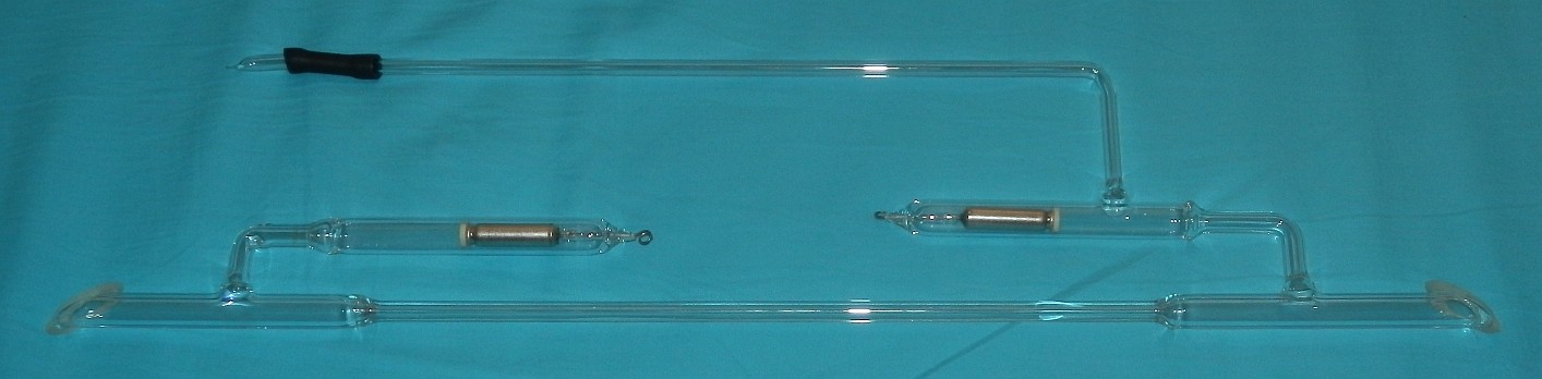
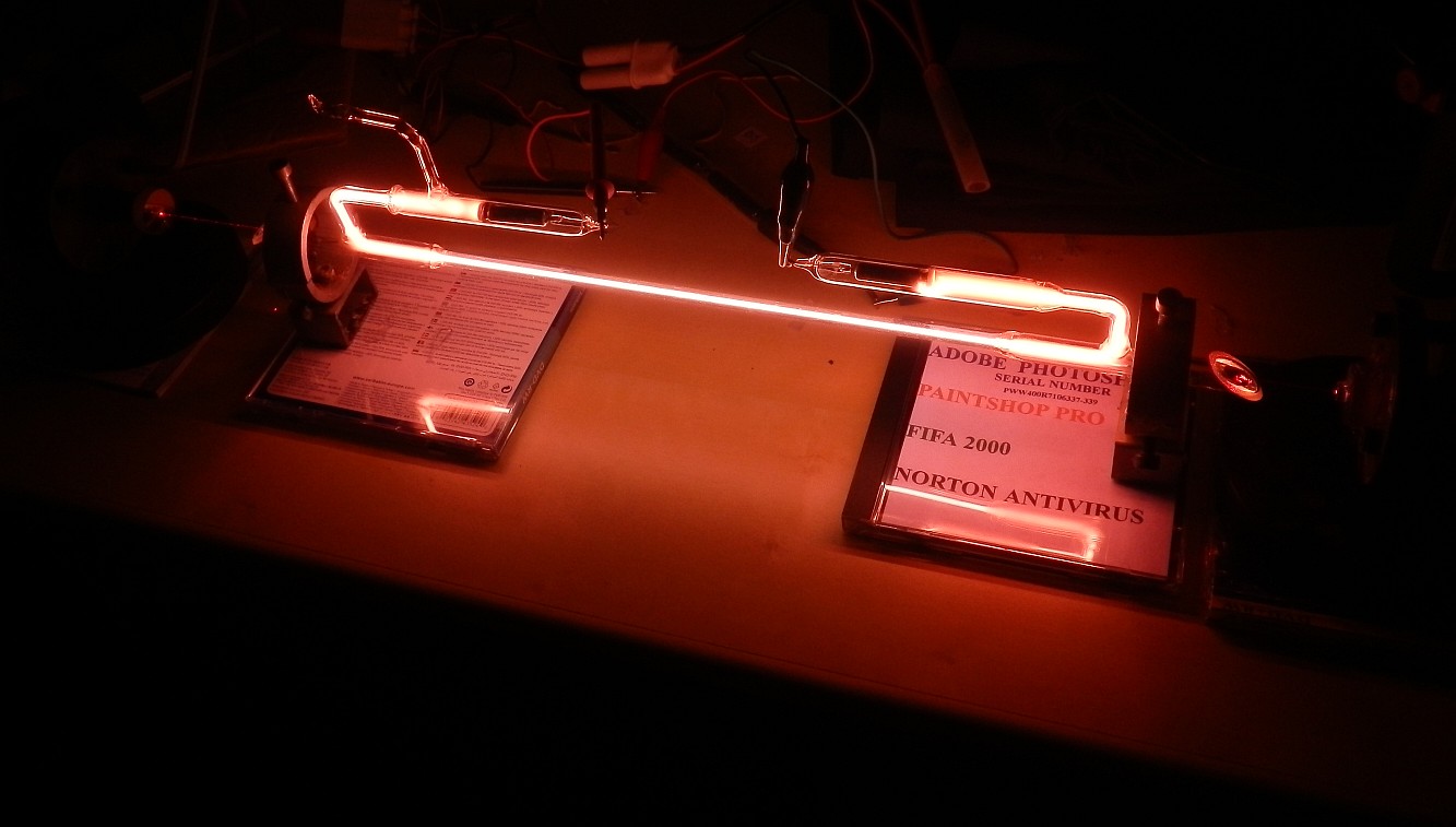
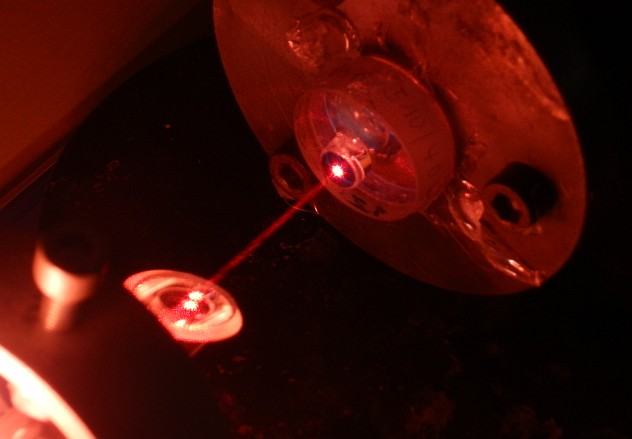
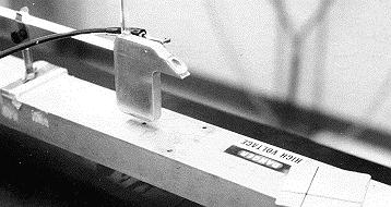
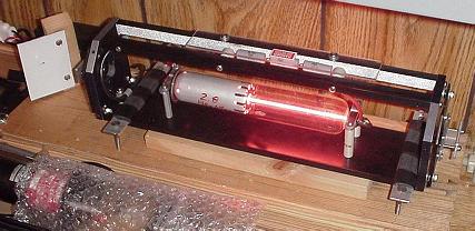
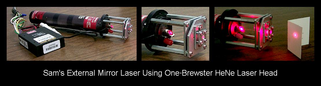
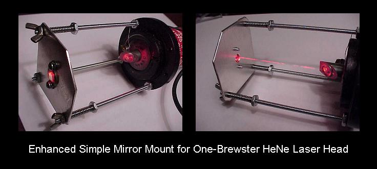
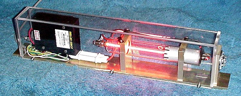
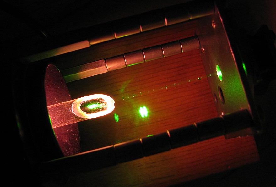
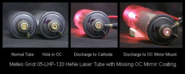
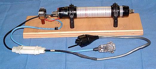
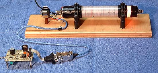
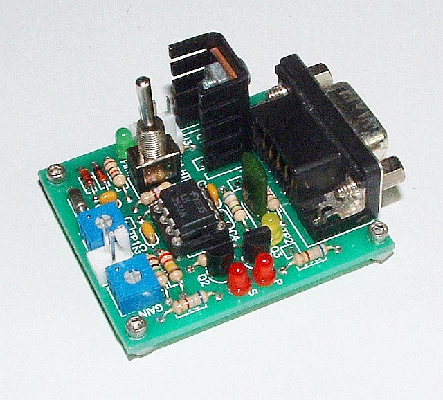
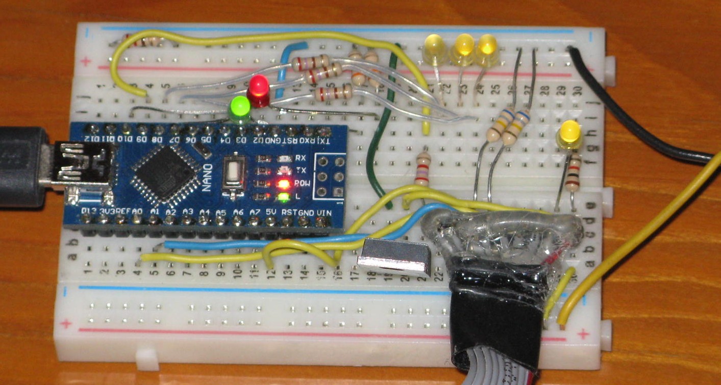
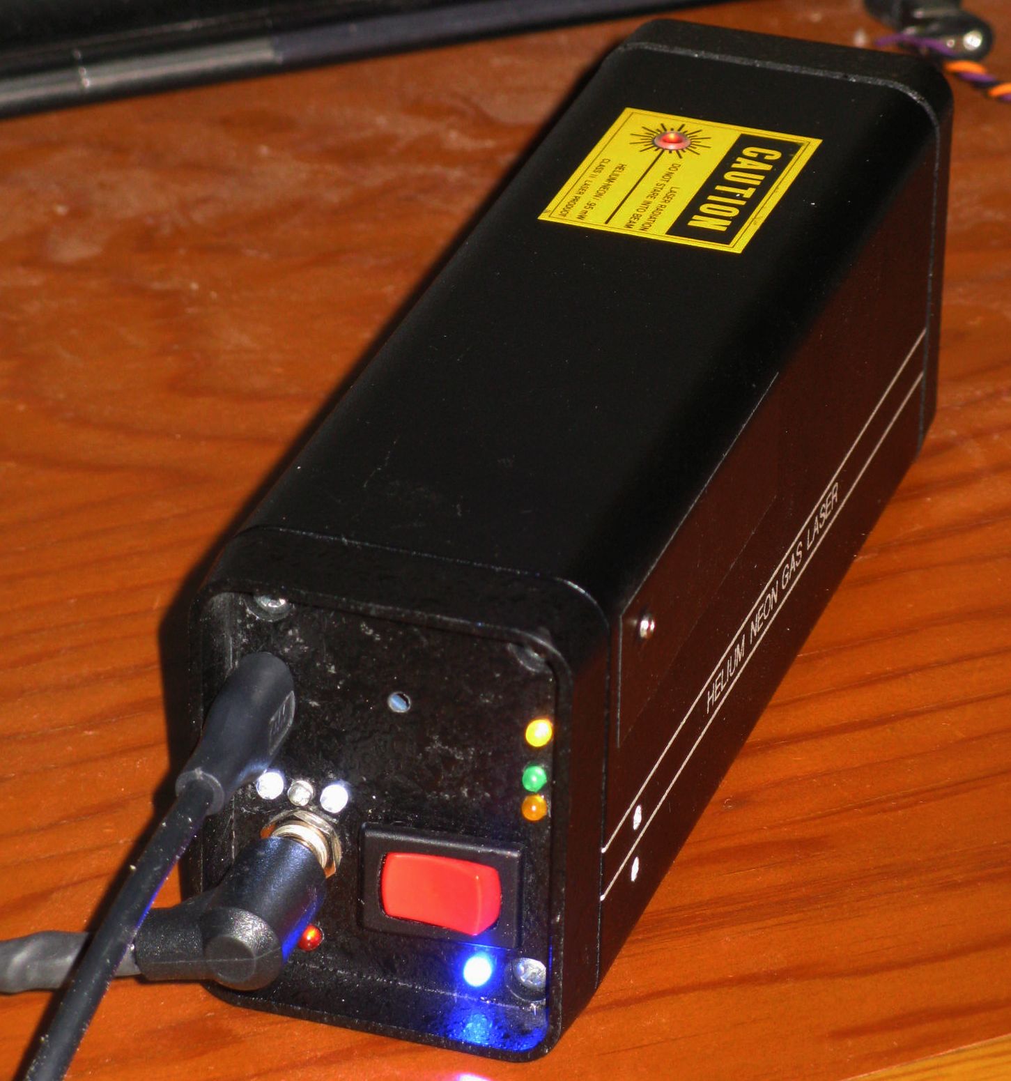
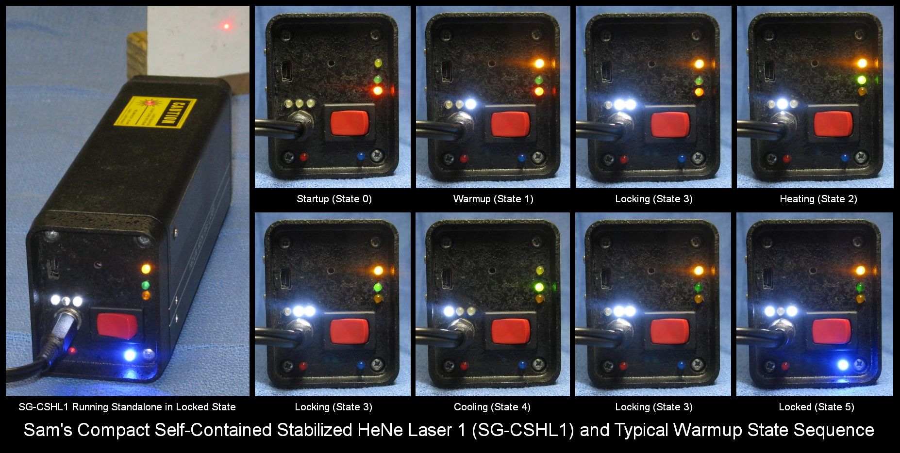
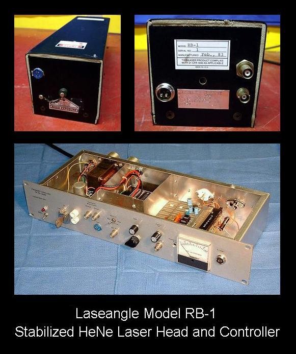
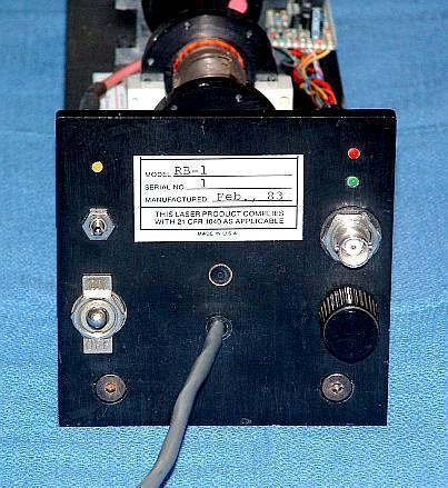
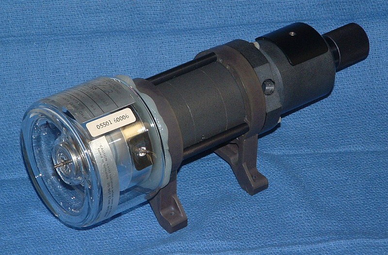
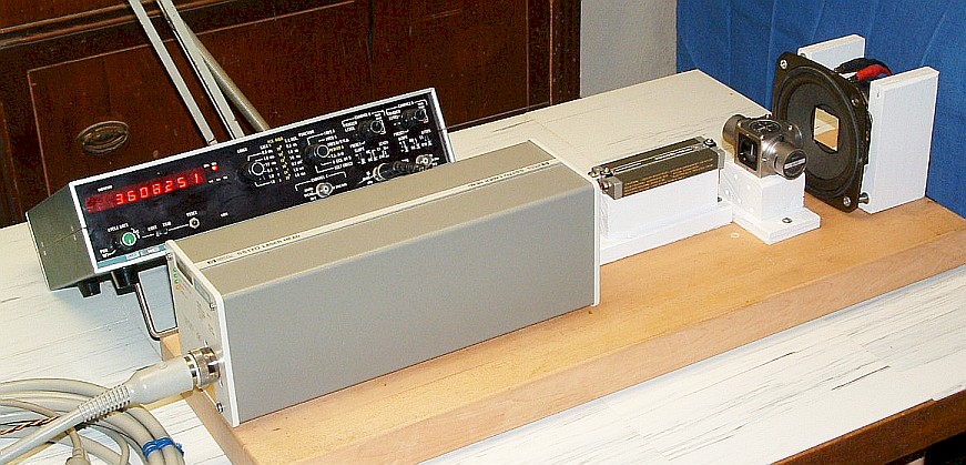
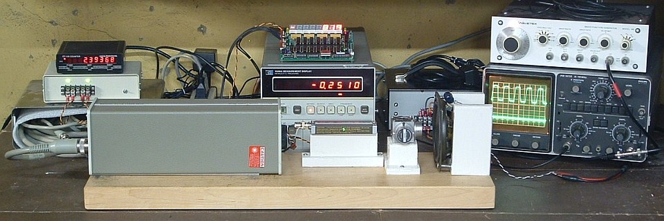
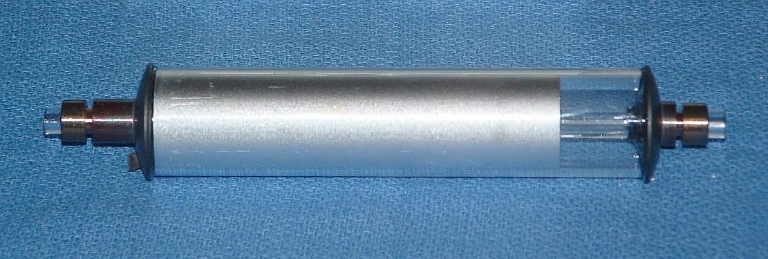
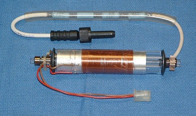
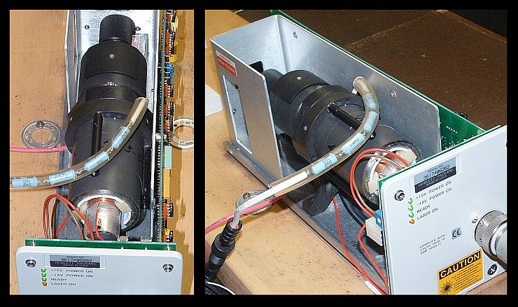
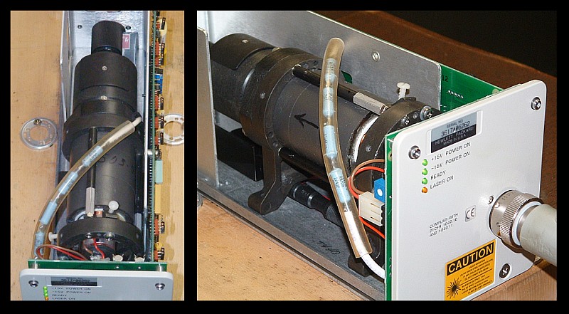
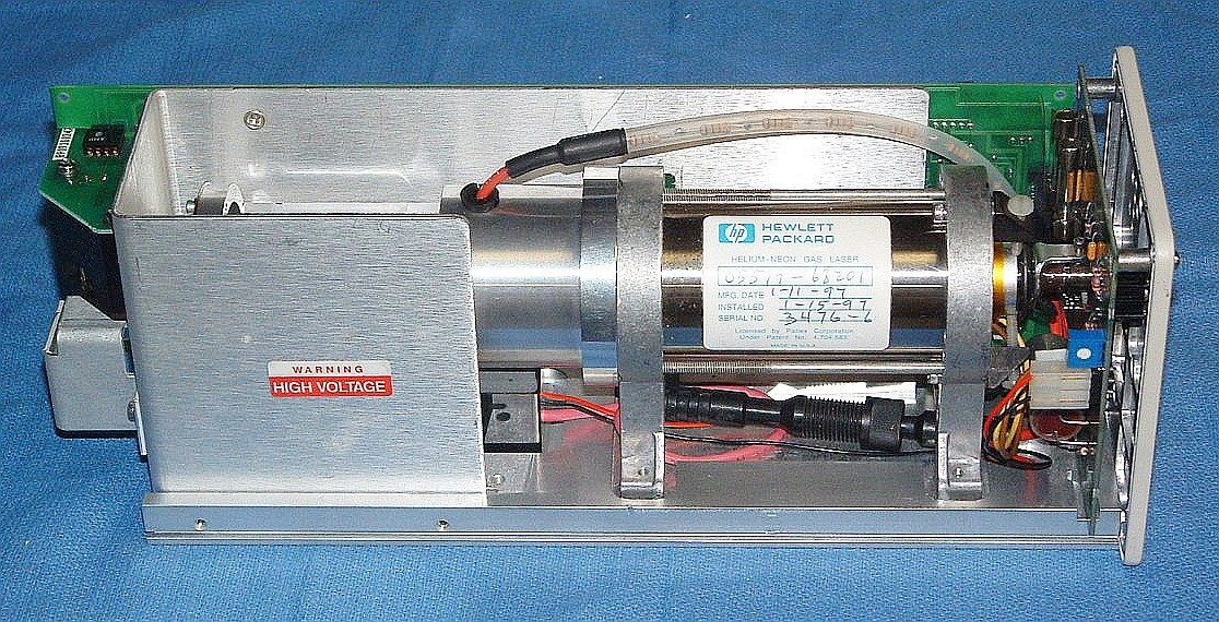
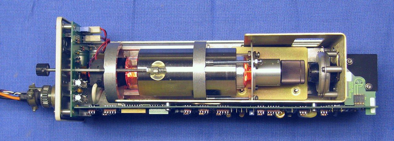
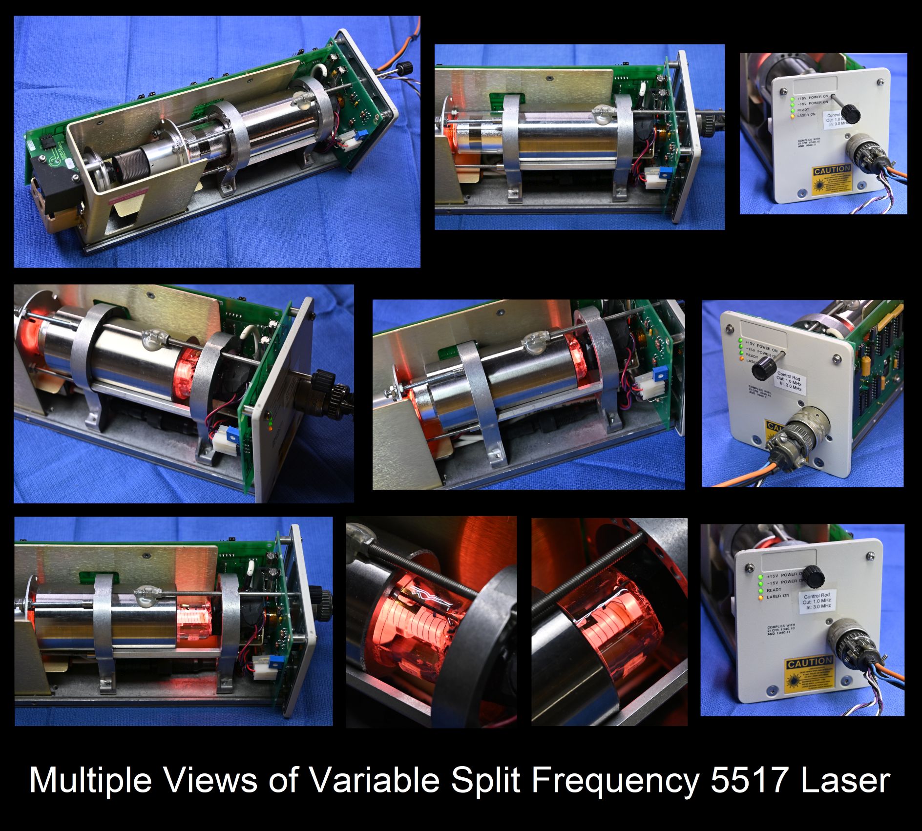
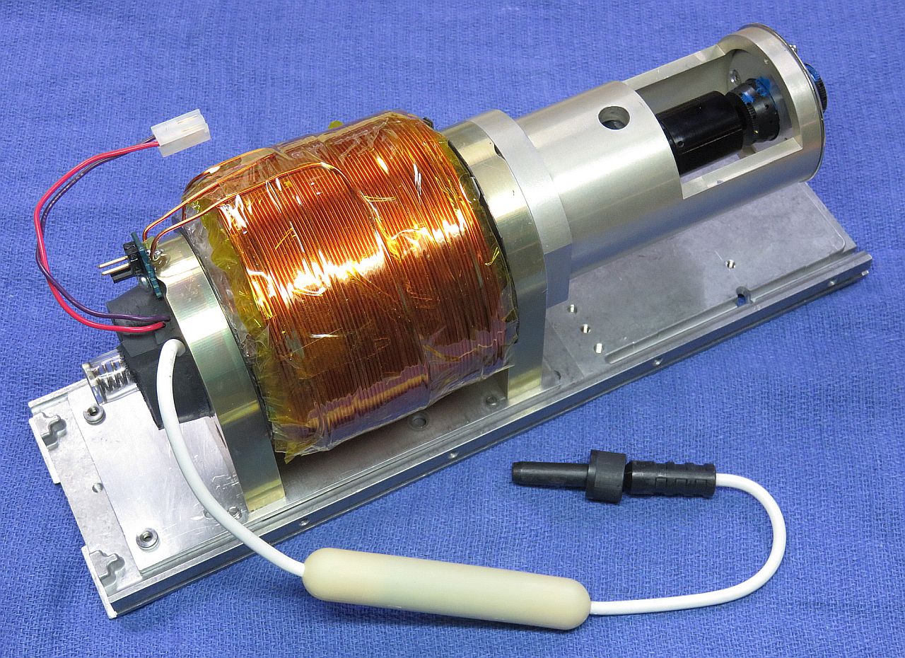
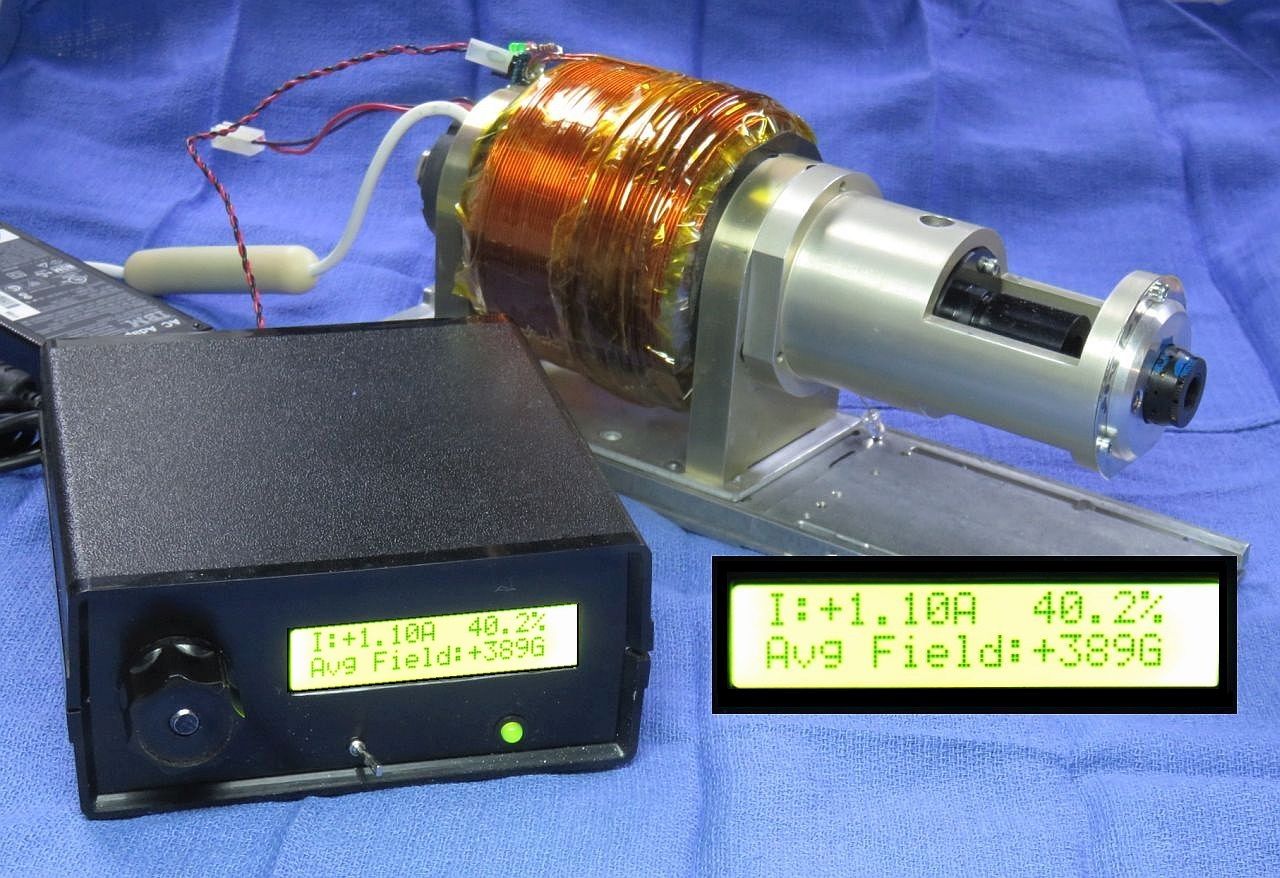
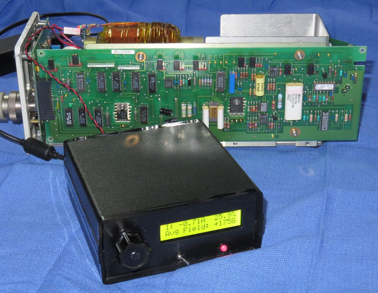
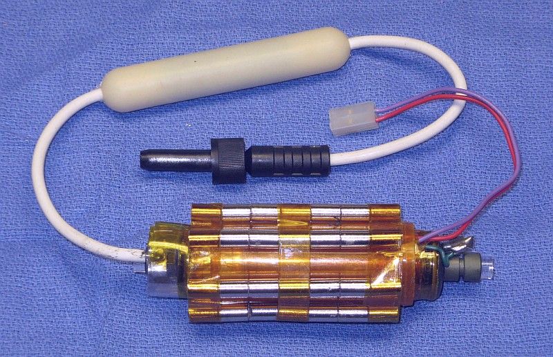
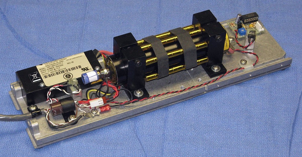
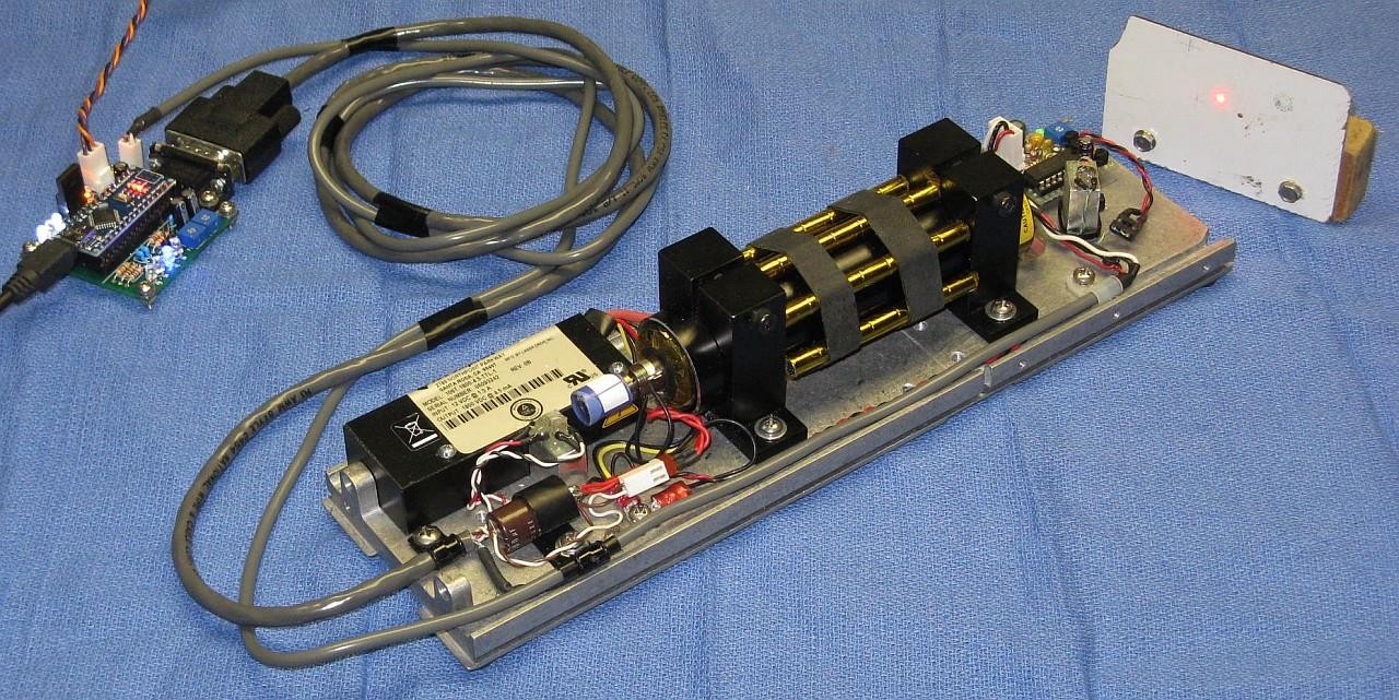
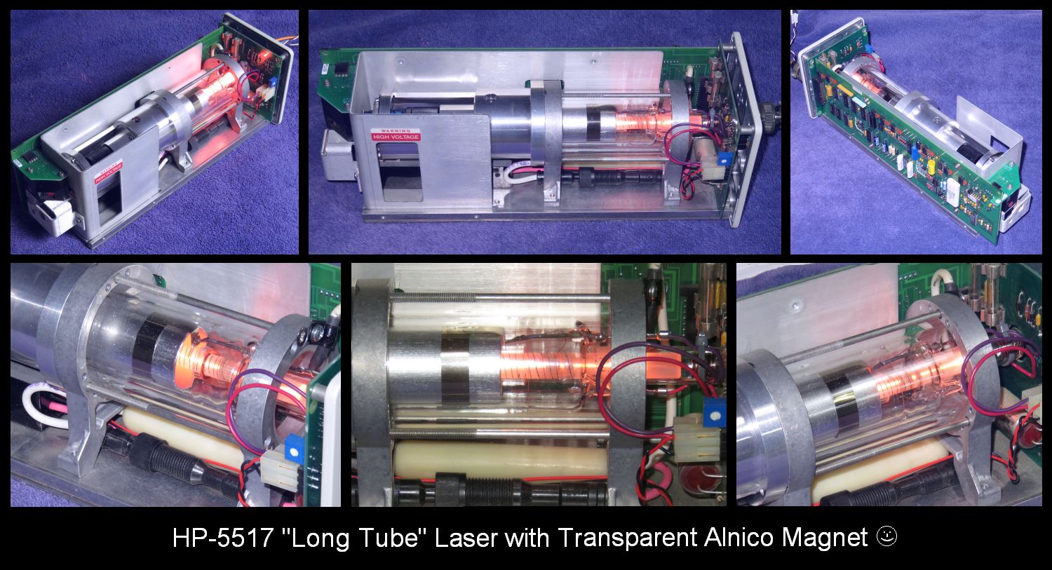
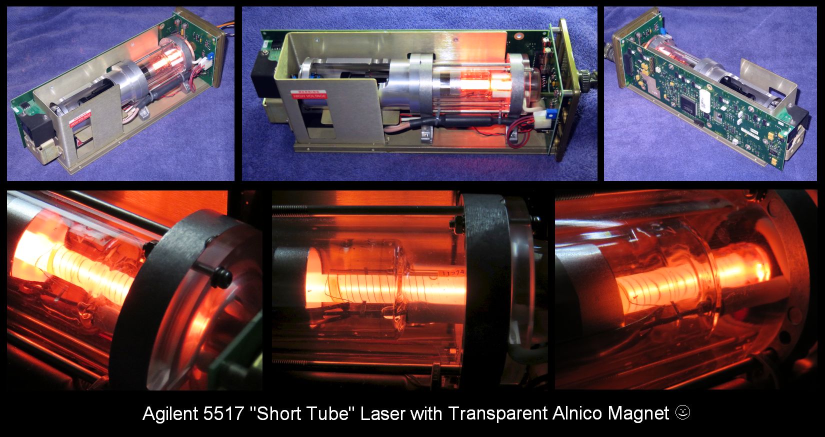
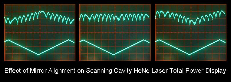
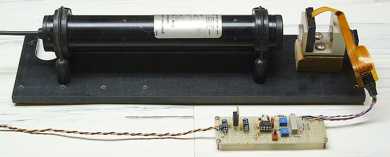